battery location JEEP LIBERTY 2002 KJ / 1.G Owner's Manual
[x] Cancel search | Manufacturer: JEEP, Model Year: 2002, Model line: LIBERTY, Model: JEEP LIBERTY 2002 KJ / 1.GPages: 1803, PDF Size: 62.3 MB
Page 323 of 1803

BOTH SEATS INOPERATIVE
If both seats (driver and passenger) fail to heat
and the indicator lamps on the heated seat switches
for both seats fail to operate, test the heated seat
fuses in the junction block. If the heated seat fuses
check OK, go to Step 1.
(1) Back-probe the heated seat module wire har-
ness connector, do not disconnect. Check for continu-
ity between the ground circuit cavity #13 of the
heated seat module connector and a good ground. If
OK go to Step 2. If NOT OK, repair the open or
shorted ground circuit as required.
(2) Back-probe the heated seat module wire har-
ness connector, do not disconnect. Check cavity #4
and #6 for battery voltage, voltage should be present,
If OK go to Step 3. If NOT OK repair the open or
shorted fused B(+) circuit as required.
(3) Back-probe the heated seat module wire har-
ness connector, do not disconnect. Check cavity #2 for
approx. 5v, voltage should be present, replace the
heated seat control module with a known good mod-
ule and verify system operation.
REMOVAL
(1) Working under the front seat cushion (Fig. 16),
remove the heated seat module from its mounting
bracket by gently prying the module off of the two
mounting pushpins.
(2) Disconnect the seat wire harness connector
from the connector receptacle on the side of the
heated seat module.
(3) Remove the heated seat module from the vehi-
cle.
INSTALLATION
(1) Connect the seat wire harness connector to the
connector receptacle on the side of the heated seat
module.
(2) Install the heated seat module on its mounting
bracket under the front seat.
(3) Verify heated seat system operation.
Fig. 16 Heated Seat Module Location
1 - Front Seat Cushion
2 - Heated Seat Module
3 - Electrical Connector
8E - 24 ELECTRONIC CONTROL MODULESKJ
HEATED SEAT MODULE (Continued)
Page 325 of 1803

²Battery Thermal Guard- The battery thermal
guard insulates the battery to protect it from engine
compartment temperature extremes.
²Battery Tray- The battery tray provides a
secure mounting location in the vehicle for the bat-
tery and an anchor point for the battery holddown
hardware.
For battery system maintenance schedules and
jump starting procedures, see the owner's manual in
the vehicle glove box. Optionally, refer to Lubrication
and Maintenance for the proper battery jump start-
ing procedures. While battery charging can be consid-
ered a maintenance procedure, the battery charging
procedures and related information are located in the
service procedures section of this service manual.
This was done because the battery must be fully-
charged before any battery system diagnosis or test-
ing procedures can be performed. Refer to Standard
Procedures for the proper battery charging proce-
dures.
OPERATION
The battery system is designed to provide a safe,
efficient, reliable and mobile means of delivering and
storing electrical energy. This electrical energy is
required to operate the engine starting system, as
well as to operate many of the other vehicle acces-
sory systems for limited durations while the engine
and/or the charging system are not operating. The
battery system is also designed to provide a reserve
of electrical energy to supplement the charging sys-
tem for short durations while the engine is running
and the electrical current demands of the vehicle
exceed the output of the charging system. In addition
to delivering, and storing electrical energy for the
vehicle, the battery system serves as a capacitor and
voltage stabilizer for the vehicle electrical system. It
absorbs most abnormal or transient voltages caused
by the switching of any of the electrical components
or circuits in the vehicle.
DIAGNOSIS AND TESTING - BATTERY SYSTEM
The battery, starting, and charging systems in the
vehicle operate with one another and must be testedas a complete system. In order for the engine to start
and the battery to maintain its charge properly, all of
the components that are used in these systems must
perform within specifications. It is important that
the battery, starting, and charging systems be thor-
oughly tested and inspected any time a battery needs
to be charged or replaced. The cause of abnormal bat-
tery discharge, overcharging or early battery failure
must be diagnosed and corrected before a battery is
replaced and before a vehicle is returned to service.
The service information for these systems has been
separated within this service manual to make it eas-
ier to locate the specific information you are seeking.
However, when attempting to diagnose any of these
systems, it is important that you keep their interde-
pendency in mind.
The diagnostic procedures used for the battery,
starting, and charging systems include the most
basic conventional diagnostic methods, to the more
sophisticated On-Board Diagnostics (OBD) built into
the Powertrain Control Module (PCM). Use of an
induction-type milliampere ammeter, a volt/ohmme-
ter, a battery charger, a carbon pile rheostat (load
tester) and a 12-volt test lamp may be required. All
OBD-sensed systems are monitored by the PCM.
Each monitored circuit is assigned a Diagnostic Trou-
ble Code (DTC). The PCM will store a DTC in elec-
tronic memory for any failure it detects. Refer to
Charging System for the proper charging system on-
board diagnostic test procedures.
MIDTRONICS ELECTRICAL SYSTEM TESTER
The Midtronicstautomotive battery and charging
system tester is designed to help the dealership tech-
nicians diagnose the cause of a defective battery or
charging system. Follow the instruction manual sup-
plied with the tester to properly diagnose a vehicle. If
the instruction manual is not available refer to the
standard procedure in this section, which includes
the directions for using the midtronics electrical sys-
tem tester.
8F - 2 BATTERY SYSTEMKJ
BATTERY SYSTEM (Continued)
Page 339 of 1803
negative jumper posts. Select TESTING AT JUMPER
POST when connecting to that location.
(3) Connect the tester to the battery or jumper
posts, the red clamp to positive (+) and the black
clamp to negative (±).
NOTE: Multiple batteries connected in parallel must
have the ground cable disconnected to perform a
battery test. Failure to disconnect may result in
false battery test readings.
NOTE: When testing the battery in a PT Cruiser,
always test at the battery terminals
(4) Using the ARROW key selectinoroutof vehi-
cle testing and press ENTER to make a selection.
(5) If not selected, choose the Cold Cranking Amp
(CCA) battery rating. Or select the appropriate bat-
tery rating for your area (see menu). The tester will
then run its self programmed test of the battery and
display the results. Refer to the test result table
noted below.
CAUTION: If REPLACE BATTERY is the result of the
test, this may mean a poor connection between the
vehicle's cables and battery exists. After discon-
necting the vehicle's battery cables from the bat-
tery, retest the battery using the OUT-OF-VEHICLE
test before replacing.
(6) While viewing the battery test result, press the
CODE button and the tester will prompt you for the
last 4 digits of the VIN. Use the UP/DOWN arrow
buttons to scroll to the correct character; then press
ENTER to select and move to the next digit. Then
press the ENTER button to view the SERVICE
CODE. Pressing the CODE button a second time will
return you to the test results.
BATTERY TEST RESULTS
GOOD BATTERY Return to service
GOOD - RECHARGE Fully charge battery and
return to service
CHARGE & RETEST Fully charge battery and
retest battery
REPLACE BATTERY Replace the battery and
retest complete system
BAD-CELL REPLACE Replace the battery and
retest complete system
NOTE: The SERVICE CODE is required on every
warranty claim submitted for battery replacement.
REMOVAL
(1) Turn the ignition switch to the Off position. Be
certain that all electrical accessories are turned off.
(2) Loosen the battery negative cable terminal
clamp pinch-bolt hex nut.
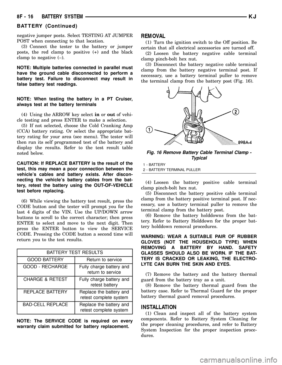
(3) Disconnect the battery negative cable terminal
clamp from the battery negative terminal post. If
necessary, use a battery terminal puller to remove
the terminal clamp from the battery post (Fig. 16).
(4) Loosen the battery positive cable terminal
clamp pinch-bolt hex nut.
(5) Disconnect the battery positive cable terminal
clamp from the battery positive terminal post. If nec-
essary, use a battery terminal puller to remove the
terminal clamp from the battery post.
(6) Remove the battery holddowns from the bat-
tery. Refer to Battery Holddown for the proper bat-
tery holddown removal procedures.
WARNING: WEAR A SUITABLE PAIR OF RUBBER
GLOVES (NOT THE HOUSEHOLD TYPE) WHEN
REMOVING A BATTERY BY HAND. SAFETY
GLASSES SHOULD ALSO BE WORN. IF THE BAT-
TERY IS CRACKED OR LEAKING, THE ELECTRO-
LYTE CAN BURN THE SKIN AND EYES.
(7) Remove the battery and the battery thermal
guard from the battery tray as a unit.
(8) Remove the battery thermal guard from the
battery case. Refer to Thermal Guard for the proper
battery thermal guard removal procedures.
INSTALLATION
(1) Clean and inspect all of the battery system
components. Refer to Battery System Cleaning for
the proper cleaning procedures, and refer to Battery
System Inspection for the proper inspection proce-
dures.
Fig. 16 Remove Battery Cable Terminal Clamp -
Typical
1 - BATTERY
2 - BATTERY TERMINAL PULLER
8F - 16 BATTERY SYSTEMKJ
BATTERY (Continued)
Page 341 of 1803

(3) Install and tighten the battery hold down
bracket retaining bolt. Tighten the bolt to 4 N´m (20
in. lbs.).
(4) Reconnect the battery negative cable terminal
clamp to the battery negative terminal post. Tighten
the terminal clamp pinch-bolt hex nut to 8.4 N´m (75
in. lbs.).
BATTERY CABLES
DESCRIPTION
The battery cables (Fig. 18) are large gauge,
stranded copper wires sheathed within a heavy plas-
tic or synthetic rubber insulating jacket. The wire
used in the battery cables combines excellent flexibil-
ity and reliability with high electrical current carry-
ing capacity. The battery cables feature a clamping
type female battery terminal made of soft lead that is
die cast onto one end of the battery cable wire. A
square headed pinch-bolt and hex nut are installed
at the open end of the female battery terminal clamp.
Large eyelet type terminals are crimped onto the
opposite end of the battery cable wire and then sol-
der-dipped. The battery positive cable wires have a
red insulating jacket to provide visual identificationand feature a larger female battery terminal clamp
to allow connection to the larger battery positive ter-
minal post. The battery negative cable wires have a
black insulating jacket and a smaller female battery
terminal clamp.
The battery cables cannot be repaired and, if dam-
aged or faulty they must be replaced. Both the bat-
tery positive and negative cables are available for
service replacement only as a unit with the battery
wire harness, which may include portions of the wir-
ing circuits for the generator and other components
on some models. Refer to the appropriate wiring
information in this service manual for the location of
the proper battery cable wire harness diagrams. The
wiring information also includes proper wire and con-
nector repair procedures, further details on wire har-
ness routing and retention, as well as pin-out and
location views for the various wire harness connec-
tors, splices and grounds.
OPERATION
The battery cables connect the battery terminal
posts to the vehicle electrical system. These cables
also provide a path back to the battery for electrical
current generated by the charging system for restor-
ing the voltage potential of the battery. The female
battery terminal clamps on the ends of the battery
cable wires provide a strong and reliable connection
of the battery cable to the battery terminal posts.
The terminal pinch bolts allow the female terminal
clamps to be tightened around the male terminal
posts on the top of the battery. The eyelet terminals
secured to the opposite ends of the battery cable
wires from the female battery terminal clamps pro-
vide secure and reliable connection of the battery
cables to the vehicle electrical system.
The battery positive cable terminal clamp is die
cast onto the ends of two wires. One wire has an eye-
let terminal that connects the battery positive cable
to the B(+) terminal studs of the Power Distribution
Center (PDC), and the other wire has an eyelet ter-
minal that connects the battery positive cable to the
B(+) terminal stud of the engine starter motor sole-
noid. The battery negative cable terminal clamp is
also die cast onto the ends of two wires. One wire
has an eyelet terminal that connects the battery neg-
ative cable to the vehicle powertrain through a stud
on the left side of the engine cylinder block. The
other wire has an eyelet terminal that connects the
battery negative cable to the vehicle body through a
ground stud on the left wheel house, near the bat-
tery.
Fig. 18 Battery Cables - Typical
1 - Battery
2 - Radiator Crossmember
3 - Terminal Clamps
4 - Fender Inner Shield
5 - Negative Cable
6 - Positive Cable
8F - 18 BATTERY SYSTEMKJ
BATTERY HOLDDOWN (Continued)
Page 342 of 1803

DIAGNOSIS AND TESTING - BATTERY CABLES
A voltage drop test will determine if there is exces-
sive resistance in the battery cable terminal connec-
tions or the battery cable. If excessive resistance is
found in the battery cable connections, the connec-
tion point should be disassembled, cleaned of all cor-
rosion or foreign material, then reassembled.
Following reassembly, check the voltage drop for the
battery cable connection and the battery cable again
to confirm repair.
When performing the voltage drop test, it is impor-
tant to remember that the voltage drop is giving an
indication of the resistance between the two points at
which the voltmeter probes are attached.EXAM-
PLE:When testing the resistance of the battery pos-
itive cable, touch the voltmeter leads to the battery
positive cable terminal clamp and to the battery pos-
itive cable eyelet terminal at the starter solenoid
B(+) terminal stud. If you probe the battery positive
terminal post and the battery positive cable eyelet
terminal at the starter solenoid B(+) terminal stud,
you are reading the combined voltage drop in the
battery positive cable terminal clamp-to-terminal
post connection and the battery positive cable.
VOLTAGE DROP TEST
The following operation will require a voltmeter
accurate to 1/10 (0.10) volt. Before performing this
test, be certain that the following procedures are
accomplished:
²The battery is fully-charged and load tested.
Refer to Standard Procedures for the proper battery
charging and load test procedures.
²Fully engage the parking brake.
²If the vehicle is equipped with an automatic
transmission, place the gearshift selector lever in the
Park position. If the vehicle is equipped with a man-
ual transmission, place the gearshift selector lever in
the Neutral position and block the clutch pedal in the
fully depressed position.
²Verify that all lamps and accessories are turned
off.
²To prevent the engine from starting, remove the
Automatic Shut Down (ASD) relay. The ASD relay is
located in the Power Distribution Center (PDC), in
the engine compartment. See the fuse and relay lay-
out label affixed to the underside of the PDC cover
for ASD relay identification and location.
(1) Connect the positive lead of the voltmeter to
the battery negative terminal post. Connect the neg-
ative lead of the voltmeter to the battery negative
cable terminal clamp (Fig. 19). Rotate and hold the
ignition switch in the Start position. Observe the
voltmeter. If voltage is detected, correct the poor con-
nection between the battery negative cable terminal
clamp and the battery negative terminal post.(2) Connect the positive lead of the voltmeter to
the battery positive terminal post. Connect the nega-
tive lead of the voltmeter to the battery positive cable
terminal clamp (Fig. 20). Rotate and hold the ignition
switch in the Start position. Observe the voltmeter. If
voltage is detected, correct the poor connection
between the battery positive cable terminal clamp
and the battery positive terminal post.
(3) Connect the voltmeter to measure between the
battery positive cable terminal clamp and the starter
solenoid B(+) terminal stud (Fig. 21). Rotate and hold
the ignition switch in the Start position. Observe the
voltmeter. If the reading is above 0.2 volt, clean and
tighten the battery positive cable eyelet terminal con-
Fig. 19 TEST BATTERY NEGATIVE CONNECTION
RESISTANCE - TYPICAL
1 - VOLTMETER
2 - BATTERY
Fig. 20 TEST BATTERY POSITIVE CONNECTION
RESISTANCE - TYPICAL
1 - VOLTMETER
2 - BATTERY
KJBATTERY SYSTEM 8F - 19
BATTERY CABLES (Continued)
Page 344 of 1803

(2) Carefully and evenly slide the battery thermal
guard down over the battery case.
(3) Install the battery and the battery thermal
guard into the battery tray as a unit. Refer to Bat-
tery Installation for the proper battery installation
procedures.
BATTERY TRAY
DESCRIPTION
The battery is placed in a molded plastic tray
located in the left front corner of the engine compart-
ment (Fig. 25). The battery hold down hardware is
contained within the battery tray. A hole in the bot-
tom of the battery tray is fitted with a battery tem-
perature sensor. Refer to Charging System for more
information on the battery temperature sensor. Refer
to Battery Hold down for more information on hold
down hardware.
OPERATION
The battery tray provides a secure mounting loca-
tion and supports the battery. On some vehicles, the
battery tray also provides the anchor point/s for the
battery holddown hardware. The battery tray and
the battery holddown hardware combine to secure
and stabilize the battery in the engine compartment,
which prevents battery movement during vehicle
operation. Unrestrained battery movement during
vehicle operation could result in damage to the vehi-
cle, the battery, or both.
REMOVAL
(1) Remove the battery from the battery tray
(Refer to 8 - ELECTRICAL/BATTERY SYSTEM/BAT-
TERY - REMOVAL).
(2) Unlatch and remove the PDC from the battery
tray.
(3) Remove the battery temperature sensor from
the battery tray (Refer to 8 - ELECTRICAL/CHARG-
ING/BATTERY TEMPERATURE SENSOR -
REMOVAL).
(4) Remove the three nuts that secure the battery
tray to the weld studs on the front extension of the
left front wheelhouse inner panel (Fig. 25).
(5) Remove the battery tray from the vehicle.
INSTALLATION
(1) Clean and inspect the battery tray (Refer to 8 -
ELECTRICAL/BATTERY SYSTEM - CLEANING).
(2) Position the battery tray onto the weld studs
on the front extension of the left front wheelhouse
inner panel.
(3) Install the battery temperature sensor onto the
battery tray (Refer to 8 - ELECTRICAL/CHARGING/
BATTERY TEMPERATURE SENSOR - INSTALLA-
TION).
(4) Install and tighten the three nuts that secure
the battery tray to the weld studs on the front exten-
sion of the left front wheelhouse inner panel. Tighten
the nuts to 5 N´m (45 in. lbs.).
(5) Install the PDC on the battery tray.
(6) Install the battery onto the battery tray (Refer
to 8 - ELECTRICAL/BATTERY SYSTEM/BATTERY -
INSTALLATION).
Fig. 24 Battery thermal guard
1 - THERMAL GUARD
2 - BATTERY
Fig. 25 Battery Tray Location
1 - Battery Tray
2 - Battery Tray Retaining Nuts
KJBATTERY SYSTEM 8F - 21
THERMAL GUARD (Continued)
Page 358 of 1803

TESTING
COLD CRANKING TEST
For complete starter wiring circuit diagrams, refer
to 8, Wiring Diagrams. The battery must be fully-
charged and load-tested before proceeding. Refer to
Batteryin 8, Battery.
(1) Connect volt-ampere tester to battery terminals
(Fig. 1). See instructions provided by manufacturer of
volt-ampere tester being used.Note: Certain diesel
equipped models use dual batteries. If equipped
with dual battery system, tester should be con-
nected to battery on left side of vehicle only.
Also, tester current reading must be taken from
positive battery cable lead that connects to
starter motor.
(2) Fully engage parking brake.
(3) If equipped with manual transmission, place
gearshift selector lever in Neutral position and block
clutch pedal in fully depressed position. If equipped
with automatic transmission, place gearshift selector
lever in Park position.
(4) Verify that all lamps and accessories are
turned off.
(5) To prevent a gasoline engine from starting,
remove Automatic ShutDown (ASD) relay. To prevent
a diesel engine from starting, remove Fuel Pump
Relay. These relays are located in Power Distribution
Center (PDC). Refer to label on PDC cover for relay
location.
WARNING: IF EQUIPPED WITH DIESEL ENGINE,
ATTEMPT TO START ENGINE A FEW TIMES
BEFORE PROCEEDING WITH FOLLOWING STEP.(6) Rotate and hold ignition switch in Start posi-
tion. Note cranking voltage and current (amperage)
draw readings shown on volt-ampere tester.
(a) If voltage reads below 9.6 volts, refer to
Starter Motorin Diagnosis and Testing. If starter
motor is OK, refer toEngine Diagnosisin 9,
Engine for further testing of engine. If starter
motor is not OK, replace faulty starter motor.
(b) If voltage reads above 9.6 volts and current
(amperage) draw reads below specifications, refer
toFeed Circuit Testin this section.
(c) If voltage reads 12.5 volts or greater and
starter motor does not turn, refer toControl Cir-
cuit Testingin this section.
(d) If voltage reads 12.5 volts or greater and
starter motor turns very slowly, refer toFeed Cir-
cuit Testin this section.
NOTE: A cold engine will increase starter current
(amperage) draw reading, and reduce battery volt-
age reading.
FEED CIRCUIT TEST
The starter feed circuit test (voltage drop method)
will determine if there is excessive resistance in
high-amperage feed circuit. For complete starter wir-
ing circuit diagrams, refer 8, Wiring Diagrams.
When performing these tests, it is important to
remember that voltage drop is giving an indication of
resistance between two points at which voltmeter
probes are attached.
Example:When testing resistance of positive bat-
tery cable, touch voltmeter leads to positive battery
cable clamp and cable connector at starter solenoid.
If you probe positive battery terminal post and cable
connector at starter solenoid, you are reading com-
bined voltage drop in positive battery cable clamp-to-
terminal post connection and positive battery cable.
The following operation will require a voltmeter
accurate to 1/10 (0.10) volt. Before performing tests,
be certain that following procedures are accom-
plished:
²Battery is fully-charged and load-tested. Refer to
Batteryin 8, Battery.
²Fully engage parking brake.
²If equipped with manual transmission, place
gearshift selector lever in Neutral position and block
clutch pedal in fully depressed position. If equipped
with automatic transmission, place gearshift selector
lever in Park position.
²Verify that all lamps and accessories are turned
off.
²To prevent a gasoline engine from starting,
remove Automatic ShutDown (ASD) relay. To prevent
a diesel engine from starting, remove Fuel Pump
Relay. These relays are located in Power Distribution
Fig. 1 Volts-Amps Tester Connections - Typical
1 - POSITIVE CLAMP
2 - NEGATIVE CLAMP
3 - INDUCTION AMMETER CLAMP
KJSTARTING SYSTEM 8F - 35
STARTING SYSTEM (Continued)
Page 359 of 1803

Center (PDC). Refer to label on PDC cover for relay
location.
(1) Connect positive lead of voltmeter to negative
battery cable terminal post. Connect negative lead of
voltmeter to negative battery cable clamp (Fig. 2).
Rotate and hold ignition switch in Start position.
Observe voltmeter. If voltage is detected, correct poor
contact between cable clamp and terminal post.
Note: Certain diesel equipped models use dual
batteries. If equipped with dual battery system,
procedure must be performed twice, once for
each battery.
(2) Connect positive lead of voltmeter to positive
battery terminal post. Connect negative lead of volt-
meter to battery positive cable clamp (Fig. 3). Rotate
and hold ignition switch in Start position. Observe
voltmeter. If voltage is detected, correct poor contact
between cable clamp and terminal post.Note: Cer-
tain diesel equipped models use dual batteries.
If equipped with dual battery system, this pro-
cedure must be performed twice, once for each
battery.
(3) Connect voltmeter to measure between battery
positive terminal post and starter solenoid battery
terminal stud (Fig. 4). Rotate and hold ignition
switch in Start position. Observe voltmeter. If read-
ing is above 0.2 volt, clean and tighten battery cable
connection at solenoid. Repeat test. If reading is still
above 0.2 volt, replace faulty positive battery cable.
Note: Certain diesel equipped models use dual
batteries. If equipped with dual battery system,
this procedure must be performed on driver
side battery only.
(4) Connect voltmeter to measure between nega-
tive battery terminal post and a good clean groundon engine block (Fig. 5). Rotate and hold ignition
switch in Start position. Observe voltmeter. If read-
ing is above 0.2 volt, clean and tighten negative bat-
tery cable attachment on engine block. Repeat test. If
reading is still above 0.2 volt, replace faulty negative
battery cable.Note: Certain diesel equipped mod-
els use dual batteries. If equipped with dual
battery system, this procedure must be per-
formed twice, once for each battery.
(5) Connect positive lead of voltmeter to starter
housing. Connect negative lead of voltmeter to nega-
tive battery terminal post (Fig. 6). Rotate and hold
ignition switch in Start position. Observe voltmeter.
If reading is above 0.2 volt, correct poor starter to
engine block ground contact.Note: Certain diesel
Fig. 2 Test Negative Battery Cable Connection
Resistance - Typical
1 - VOLTMETER
2 - BATTERY
Fig. 3 Test Positive Battery Cable Connection
Resistance - Typical
1 - VOLTMETER
2 - BATTERY
Fig. 4 Test Positive Battery Cable
1 - BATTERY
2 - VOLTMETER
3 - STARTER MOTOR
8F - 36 STARTING SYSTEMKJ
STARTING SYSTEM (Continued)
Page 364 of 1803

INSTALLATION
2.4L 4±Cylinder
(1) Position starter into bellhousing and install 2
bolts. Refer to torque specifications.
(2) Install battery cable and nut to stud on starter
solenoid. Refer to torque specifications.
(3) Install solenoid wire connector to solenoid ter-
minal.
(4) Lower vehicle.
(5) Connect negative battery cable.
3.7L V-6
(1) Position front of starter towards rear of vehicle
with solenoid position rotated until it is located below
starter. Install starter by passing it between exhaust
pipe and transmission bellhousing.
(2) Position starter into bellhousing and install 2
bolts. Refer to torque specifications.
(3) Install battery cable and nut to stud on starter
solenoid. Refer to torque specifications.
(4) Install solenoid wire connector to solenoid ter-
minal.
(5) Position starter heat shield and install nut at
front of starter.
(6) Install 2 starter heat shield bolts at side of
starter.
(7) Install front propeller shaft.
(8) Install 2 flange bolts securing left exhaust
downpipe to crossover pipe.
(9) Lower vehicle.
(10) Connect negative battery cable.
STARTER MOTOR RELAY
DESCRIPTION
The starter relay is an electromechanical device
that switches battery current to the pull-in coil of the
starter solenoid when ignition switch is turned to
Start position. The starter relay is located in the
Power Distribution Center (PDC) in the engine com-
partment. See PDC cover for relay identification and
location.
The starter relay is a International Standards
Organization (ISO) relay. Relays conforming to ISO
specifications have common physical dimensions, cur-
rent capacities, terminal patterns, and terminal func-
tions.
The starter relay cannot be repaired or adjusted
and, if faulty or damaged, it must be replaced.
Fig. 11 STARTER ELECTRICAL CONNECTORS -
2.4L/3.7L
1 - BATERY CABLE NUT
2 - BATTERY CABLE
3 - SOLENOID CONNECTOR
4 - HEAT SHIELD
Fig. 12 STARTER - 3.7L
1-STARTER
2 - MOUNTING BOLTS (2)
KJSTARTING SYSTEM 8F - 41
STARTER MOTOR (Continued)
Page 365 of 1803

OPERATION
The ISO relay consists of an electromagnetic coil, a
resistor or diode, and three (two fixed and one mov-
able) electrical contacts. The movable (common feed)
relay contact is held against one of the fixed contacts
(normally closed) by spring pressure. When electro-
magnetic coil is energized, it draws the movable con-
tact away from normally closed fixed contact, and
holds it against the other (normally open) fixed con-
tact.
When electromagnetic coil is de-energized, spring
pressure returns movable contact to normally closed
position. The resistor or diode is connected in parallel
with electromagnetic coil within relay, and helps to
dissipate voltage spikes produced when coil is de-en-
ergized.
DIAGNOSIS AND TESTING - STARTER RELAY
The starter relay is located in the Power Distribu-
tion Center (PDC) in engine compartment. Refer to
label on PDC cover for relay location.
RELAY TEST
(1) Remove starter relay (Fig. 13) from PDC.
(2) A relay in de-energized position should have
continuity between terminals 87A and 30, and no
continuity between terminals 87 and 30. If OK, go to
Step 3. If not OK, replace faulty relay.
(3) Resistance between terminals 85 and 86 (elec-
tromagnet) should be 75 5 ohms. If OK, go to Step
4. If not OK, replace faulty relay.
(4) Connect a battery to terminals 85 and 86.
There should now be continuity between terminals
30 and 87, and no continuity between terminals 87A
and 30. If OK, perform following Relay Circuit Test.
If not OK, replace faulty relay.
RELAY CIRCUIT TEST
(1) The relay common feed terminal cavity (30) is
connected to battery voltage and should be hot at all
times. If OK, go to Step 2. If not OK, repair open cir-
cuit to fused B(+) fuse in PDC as required.
(2) The relay normally closed terminal (87A) is
connected to terminal 30 in de-energized position,
but is not used for this application. Go to Step 3.
(3) The relay normally open terminal (87) is con-
nected to common feed terminal (30) in energized
position. This terminal supplies battery voltage to
starter solenoid field coil. There should be continuity
between cavity for relay terminal 87 and starter sole-
noid terminal at all times. If OK, go to Step 4. If not
OK, repair open engine starter motor relay output
circuit to starter solenoid as required.
(4) The coil battery terminal (86) is connected to
electromagnet in relay. It is energized when ignition
switch is held in Start position. On vehicles with amanual transmission, the clutch pedal must be
blocked in fully depressed position for this test.
Check for battery voltage at cavity for relay terminal
86 with ignition switch in Start position, and no volt-
age when ignition switch is released to On position.
If OK, go to Step 5. If not OK with a manual trans-
mission, disconnect clutch pedal position switch wire
harness connector and install a jumper wire between
two cavities in body half of connector and check for
battery voltage again at cavity for relay terminal 86.
If now OK, replace faulty clutch pedal position
switch. If still not OK with a manual transmission or
if not OK with an automatic transmission, check for
open or shorted fused ignition switch output (start)
circuit to ignition switch and repair as required. If
fused ignition switch output (start) circuit is OK,
refer toIgnition Switch and Key Lock Cylinder.
(5) The coil ground terminal (85) is connected to
electromagnet in relay. On vehicles with manual
transmission, it is grounded at all times. On vehicles
with automatic transmission, it is grounded through
park/neutral position switch only when gearshift
selector lever is in Park or Neutral positions. Check
for continuity to ground at cavity for relay terminal
85. If not OK with a manual transmission, repair
open park/neutral position switch sense circuit to
ground as required. If not OK with an automatic
transmission, check for open or shorted park/neutral
position switch sense circuit to park/neutral position
switch and repair, as required. If park/neutral posi-
tion switch sense circuit checks OK, refer toPark/
Neutral Position Switch.
Fig. 13 STARTER RELAY (ISO MICRO RELAY)
30 - COMMON FEED
85 - COIL GROUND
86 - COIL BATTERY
87 - NORMALLY OPEN
87A - NORMALLY CLOSED
8F - 42 STARTING SYSTEMKJ
STARTER MOTOR RELAY (Continued)