Crank sensor wiring JEEP LIBERTY 2002 KJ / 1.G Workshop Manual
[x] Cancel search | Manufacturer: JEEP, Model Year: 2002, Model line: LIBERTY, Model: JEEP LIBERTY 2002 KJ / 1.GPages: 1803, PDF Size: 62.3 MB
Page 403 of 1803
sure the plugs do not drop into the plug wells as elec-
trodes can be damaged.
Always tighten spark plugs to the specified torque.
Over tightening can cause distortion resulting in a
change in the spark plug gap or a cracked porcelain
insulator.
(1) Start the spark plug into the cylinder head by
hand to avoid cross threading.
(2) Tighten spark plugs. Refer to torque specifica-
tions.
(3) Before installing coil(s), check condition of coil
o-ring and replace as necessary. To aid in coil instal-
lation, apply silicone to coil o-ring.
(4) Install ignition coil(s). Refer to Ignition Coil
Removal/Installation.
IGNITION COIL CAPACITOR
DESCRIPTION
One coil capacitor is used. It is located in the
engine compartment and attached (clipped) to a wir-
ing trough near the brake power booster.
OPERATION
The coil capacitor(s) help dampen the amount of
conducted electrical noise to the camshaft position
sensor, crankshaft position sensor, and throttle posi-
tion sensor. This noise is generated on the 12V sup-
ply wire to the ignition coils and fuel injectors.
REMOVAL
The coil capacitor is located in the engine compart-
ment and is attached (clipped) to a wiring harness
trough near the brake power booster (graphic not
available).
(1) Unclip capacitor from wiring harness trough.
(2) Disconnect electrical connector at capacitor.
INSTALLATION
(1) Connect electrical connector to coil capacitor.
(2) Position capacitor into v-clip on wiring harness
trough.
8I - 16 IGNITION CONTROLKJ
SPARK PLUG (Continued)
Page 1219 of 1803
DIAGNOSIS AND TESTING
DIAGNOSIS AND TESTING - ENGINE
DIAGNOSIS - INTRODUCTION
Engine diagnosis is helpful in determining the
causes of malfunctions not detected and remedied by
routine maintenance.
These malfunctions may be classified as either per-
formance (e.g., engine idles rough and stalls) or
mechanical (e.g., a strange noise).
(Refer to 9 - ENGINE - DIAGNOSIS AND TEST-
ING)ÐPERFORMANCE and (Refer to 9 - ENGINE -
DIAGNOSIS AND TESTING)ÐMECHANICAL for
possible causes and corrections of malfunctions.
(Refer to 14 - FUEL SYSTEM/FUEL DELIVERY -
DIAGNOSIS AND TESTING) and (Refer to 14 -
FUEL SYSTEM/FUEL INJECTION - DIAGNOSIS
AND TESTING) for the fuel system diagnosis.Additional tests and diagnostic procedures may be
necessary for specific engine malfunctions that can
not be isolated with the Service Diagnosis charts.
Information concerning additional tests and diagno-
sis is provided within the following diagnosis:
²Cylinder Compression Pressure Test (Refer to 9 -
ENGINE - DIAGNOSIS AND TESTING).
²Cylinder Combustion Pressure Leakage Test
(Refer to 9 - ENGINE - DIAGNOSIS AND TEST-
ING).
²Engine Cylinder Head Gasket Failure Diagnosis
(Refer to 9 - ENGINE/CYLINDER HEAD - DIAGNO-
SIS AND TESTING).
²Intake Manifold Leakage Diagnosis (Refer to 9 -
ENGINE/MANIFOLDS/INTAKE MANIFOLD -
DIAGNOSIS AND TESTING).
DIAGNOSIS AND TESTING - ENGINE DIAGNOSIS - PERFORMANCE
CONDITION POSSIBLE CAUSE CORRECTION
ENGINE WILL NOT START 1. Weak battery 1. Charge or replace as necessary.
2. Corroded or loose battery
connections.2. Clean and tighten battery
connections. Apply a coat of light
mineral grease to the terminals.
3. Faulty starter. 3. (Refer to 8 - ELECTRICAL/
STARTING - DIAGNOSIS AND
TESTING).
4. Faulty coil or control unit. 4. (Refer to 8 - ELECTRICAL/
IGNITION CONTROL/IGNITION
COIL - REMOVAL).
5. Incorrect spark plug gap. 5. (Refer to 8 - ELECTRICAL/
IGNITION CONTROL/SPARK PLUG
- CLEANING).
6. Incorrect right bank cam timing. 6. Refer to engine timing in this
section.
7. Dirt or water in fuel system. 7. Clean system and replace fuel
filter.
8.Faulty fuel pump, relay or wiring. 8.Repair or replace as necessary.
9. Faulty cam or crank sensor 9. Refer to Ignition system.
ENGINE STALLS OR ROUGH IDLE 1. Vacuum leak. 1. Inspect intake manifold and
vacuum hoses, repair or replace as
necessary.
2. Faulty crank position sensor 2. Replace crank position sensor.
4. Faulty coil. 4. (Refer to 8 - ELECTRICAL/
IGNITION CONTROL/IGNITION
COIL - REMOVAL).
9 - 4 ENGINE - 3.7LKJ
ENGINE - 3.7L (Continued)
Page 1225 of 1803
²Tapping the hole with a special Heli-Coil Tap, or
equivalent.
²Installing an insert into the tapped hole to bring
the hole back to its original thread size.
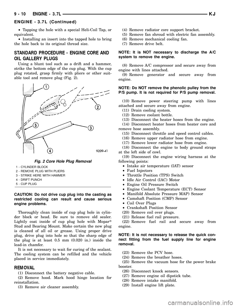
STANDARD PROCEDURE - ENGINE CORE AND
OIL GALLERY PLUGS
Using a blunt tool such as a drift and a hammer,
strike the bottom edge of the cup plug. With the cup
plug rotated, grasp firmly with pliers or other suit-
able tool and remove plug (Fig. 2).
CAUTION: Do not drive cup plug into the casting as
restricted cooling can result and cause serious
engine problems.
Thoroughly clean inside of cup plug hole in cylin-
der block or head. Be sure to remove old sealer.
Lightly coat inside of cup plug hole with Mopart
Stud and Bearing Mount. Make certain the new plug
is cleaned of all oil or grease. Using proper drive
plug, drive plug into hole so that the sharp edge of
the plug is at least 0.5 mm (0.020 in.) inside the
lead-in chamfer.
It is not necessary to wait for curing of the sealant.
The cooling system can be refilled and the vehicle
placed in service immediately.
REMOVAL
(1) Disconnect the battery negative cable.
(2) Remove hood. Mark hood hinge location for
reinstallation.
(3) Remove air cleaner assembly.(4) Remove radiator core support bracket.
(5) Remove fan shroud with electric fan assembly.
(6) Remove mechanical cooling fan.
(7) Remove drive belt.
NOTE: It is NOT necessary to discharge the A/C
system to remove the engine.
(8) Remove A/C compressor and secure away from
engine with lines attached.
(9) Remove generator and secure away from
engine.
NOTE: Do NOT remove the phenolic pulley from the
P/S pump. It is not required for P/S pump removal.
(10) Remove power steering pump with lines
attached and secure away from engine.
(11) Drain cooling system.
(12) Remove coolant bottle.
(13) Disconnect the heater hoses from the engine.
(14) Disconnect heater hoses from heater core and
remove hose assembly.
(15) Disconnect throttle and speed control cables.
(16) Remove upper radiator hose from engine.
(17) Remove lower radiator hose from engine.
(18) Disconnect the engine to body ground straps
at the left side of cowl.
(19) Disconnect the engine wiring harness at the
following points:
²Intake air temperature (IAT) sensor
²Fuel Injectors
²Throttle Position (TPS) Switch
²Idle Air Control (IAC) Motor
²Engine Oil Pressure Switch
²Engine Coolant Temperature (ECT) Sensor
²Manifold Absolute Pressure MAP) Sensor
²Camshaft Position (CMP) Sensor
²Coil Over Plugs
²Crankshaft Position Sensor
(20) Remove coil over plugs.
(21) Release fuel rail pressure.
(22) Remove fuel rail and secure away from
engine.
NOTE: It is not necessary to release the quick con-
nect fitting from the fuel supply line for engine
removal.
(23) Remove the PCV hose.
(24) Remove the breather hoses.
(25) Remove the vacuum hose for the power brake
booster.
(26) Disconnect knock sensors.
(27) Remove engine oil dipstick tube.
(28) Remove intake manifold.
(29) Install engine lift plate.
Fig. 2 Core Hole Plug Removal
1 - CYLINDER BLOCK
2 - REMOVE PLUG WITH PLIERS
3 - STRIKE HERE WITH HAMMER
4 - DRIFT PUNCH
5 - CUP PLUG
9 - 10 ENGINE - 3.7LKJ
ENGINE - 3.7L (Continued)
Page 1226 of 1803
NOTE: Recheck bolt torque for engine lift plate
before removing engine.
(30) Secure the left and right engine wiring har-
nesses away from engine.
(31) Raise vehicle.
(32) Disconnect oxygen sensor wiring.
(33) Disconnect crankshaft postion sensor.
(34) Disconnect the engine block heater power
cable, if equipped.
(35) Disconnect the front propshaft at the front
differential and secure out of way.
NOTE: It is necessary to disconnect the front prop-
shaft for access to the starter and left side exhaust
flange.
(36) Remove the starter.
(37) Remove the ground straps from the left and
right side of the block.
(38) Disconnect the right and left exhaust pipes at
the manifolds and from the crossover, and remove
from the vehicle.
NOTE: The exhaust clamps at the manifolds cannot
be reused. New clamps must be used or leaks may
occur.
NOTE: For manual transmission vehicles, the trans-
mission must be removed from the vehicle, before
the engine can be removed. The manual transmis-
sion will contact the floorpan before the engine
clears the motor mounts, so it must be removed.
(39) Remove the structural cover.
(40) Remove torque convertor bolts, and mark
location for reassembly.
(41) Remove transmission bellhousing to engine
bolts.
(42) Loosen left and right engine mount thru bolts.
NOTE: It is not necessary to completely remove
engine mount thru bolts, for engine removal.
(43) Lower the vehicle.
(44) Support the transmission with a suitable jack.
(45) Connect a suitable engine hoist to the engine
lift plate.
(46) Remove engine from vehicle.
INSTALLATION
(1) Position the engine in the vehicle.
(2) Install both left and right side engine mounts
onto engine.
(3) Raise the vehicle.(4) Install the transmission bellhousing to engine
mounting bolts. Tighten the bolts to 41 N´m (30ft.
lbs.).
(5) Tighten the engine mount thru bolts.
(6) Install the torque convertor bolts.
(7) Connect the ground straps on the left and right
side of the engine.
(8) Install the starter.
(9) Connect the crankshaft position sensor.
(10) Install the engine block heater power cable, if
equipped.
CAUTION: The structural cover requires a specific
torque sequence. Failure to follow this sequence
may cause severe damage to the cover.
(11) Install the structural cover.
NOTE: New clamps must be used on exhaust man-
ifold flanges. Failure to use new clamps may result
in exhaust leaks.
(12) Install the left and right exhaust pipes.
(13) Connect the left and right oxygen sensors.
(14) Lower vehicle.
(15) Remove the engine lift plate.
(16) Connect the knock sensors.
(17) Connect the engine to body ground straps at
the left side of the cowl.
(18) Install the intake manifold.
(19) Install the engine oil dipstick tube.
(20) Install the power brake booster vacuum hose.
(21) Install the breather hoses.
(22) Install the PCV hose.
(23) Install the fuel rail.
(24) Install the coil over plugs.
(25) Connect the engine wiring harness at the fol-
lowing points:
²Intake air temperature (IAT) sensor
²Fuel Injectors
²Throttle Position (TPS) Switch
²Idle Air Control (IAC) Motor
²Engine Oil Pressure Switch
²Engine Coolant Temperature (ECT) Sensor
²Manifold Absolute Pressure MAP) Sensor
²Camshaft Position (CMP) Sensor
²Coil Over Plugs
²Crankshaft Position Sensor
(26) Connect lower radiator hose.
(27) Connect upper radiator hose.
(28) Connect throttle and speed control cables.
(29) Install the heater hose assembly.
(30) Install coolant recovery bottle.
(31) Install the power steering pump.
(32) Install the generator.
(33) Install the A/C compressor.
(34) Install the drive belt.
KJENGINE - 3.7L 9 - 11
ENGINE - 3.7L (Continued)
Page 1309 of 1803
NOTE: Plastigage is available in a variety of clear-
ance ranges. Use the most appropriate range for
the specifications you are checking.
(4) Install the proper crankshaft bearings to
achieve the specified bearing clearances. (Refer to 9 -
ENGINE/ENGINE BLOCK/CRANKSHAFT MAIN
BEARINGS - STANDARD PROCEDURE) (Refer to 9
- ENGINE/ENGINE BLOCK/CONNECTING ROD
BEARINGS - STANDARD PROCEDURE)
REMOVAL - ENGINE ASSEMBLY
(1) Disconnect the battery negative cable.
(2) Remove hood. Mark hood hinge location for
reinstallation.
(3) Remove air cleaner assembly.
(4) Remove radiator core support bracket.
(5) Remove fan shroud with electric fan assembly.
(6) Remove drive belt.
NOTE: It is NOT necessary to discharge the A/C
system to remove the engine.
(7) Remove A/C compressor and secure away from
engine with lines attached.
(8) Remove generator and secure away from
engine.
NOTE: Do NOT remove the phenolic pulley from the
P/S pump. It is not required for P/S pump removal.
(9) Remove power steering pump with lines
attached and secure away from engine.
(10) Drain cooling system.
(11) Remove coolant bottle.
(12) Disconnect the heater hoses from the engine.
(13) Disconnect heater hoses from heater core and
remove hose assembly.
(14) Disconnect throttle and speed control cables.
(15) Remove upper radiator hose from engine.
(16) Remove lower radiator hose from engine.
(17) Disconnect the engine to body ground straps
at the left side of cowl.
(18) Disconnect the engine wiring harness at the
following points:
²Intake air temperature (IAT) sensor
²Fuel Injectors
²Throttle Position (TPS) Switch
²Idle Air Control (IAC) Motor
²Engine Oil Pressure Switch
²Engine Coolant Temperature (ECT) Sensor
²Manifold Absolute Pressure MAP) Sensor
²Camshaft Position (CMP) Sensor
²Coil Over Plugs
²Crankshaft Position Sensor
(19) Remove coil over plugs.
(20) Release fuel rail pressure.(21) Remove fuel rail and secure away from
engine.
(22) Remove the PCV hose.
(23) Remove the breather hoses.
(24) Remove the vacuum hose for the power brake
booster.
(25) Disconnect knock sensors.
(26) Secure the left and right engine wiring har-
nesses away from engine.
(27) Raise vehicle.
(28) Disconnect oxygen sensor wiring.
(29) Disconnect crankshaft postion sensor.
(30) Disconnect the engine block heater power
cable, if equipped.
(31) Disconnect the front propshaft at the front
differential and secure out of way.
(32) Remove the starter.
(33) Remove the ground straps from the engine
(34) Disconnect the exhaust pipes at the manifold.
(35) Remove the structural cover, if equipped.
(36) Remove torque convertor bolts, and mark
location for reassembly.
(37) Remove transmission bellhousing to engine
bolts.
(38) Loosen left and right engine mount thru bolts.
NOTE: It is not necessary to completely remove
engine mount thru bolts, for engine removal.
(39) Lower the vehicle.
(40) Support the transmission with a suitable jack.
(41) Connect a suitable engine hoist to the engine.
CAUTION: The 2.4L engine with manual transmis-
sions, can be removed without removing the man-
ual transmission. Use caution when attempting this
procedure as the clearance is tight.
(42) Remove engine from vehicle.
INSTALLATION - ENGINE ASSEMBLY
(1) Position the engine in the vehicle.
CAUTION: Use caution when installing 2.4L engine
into vehicle equipped with manual transmission, as
clearance is tight.
(2) Install both left and right side engine mounts
into the frame mounts.
(3) Raise the vehicle.
(4) Install the transmission bellhousing to engine
mounting bolts. Tighten the bolts to 41 N´m (30ft.
lbs.).
(5) Tighten the engine mount thru bolts.
(6) Install the torque convertor bolts.
(7) Connect the ground straps on the left and right
side of the engine.
9s - 12 ENGINEKJ
ENGINE - 2.4L (Continued)
Page 1310 of 1803
(8) Install the starter.
(9) Connect the crankshaft position sensor.
(10) Install the engine block heater power cable, if
equipped.
CAUTION: The structural cover requires a specific
torque sequence. Failure to follow this sequence
may cause severe damage to the cover.
(11) Install the structural cover.
(12) Install the exhaust pipe.
(13) Connect the oxygen sensors.
(14) Lower vehicle.
(15) Connect the knock sensors.
(16) Connect the engine to body ground straps.
(17) Install the power brake booster vacuum hose.
(18) Install the breather hoses.
(19) Install the PCV hose.
(20) Install the fuel rail.
(21) Install the coil over plugs.
(22) Reconnect the engine wiring harness at the
following points:
²Intake air temperature (IAT) sensor
²Fuel Injectors
²Throttle Position (TPS) Switch
²Idle Air Control (IAC) Motor
²Engine Oil Pressure Switch
²Engine Coolant Temperature (ECT) Sensor
²Manifold Absolute Pressure MAP) Sensor
²Camshaft Position (CMP) Sensor
²Coil Over Plugs
²Crankshaft Position Sensor
(23) Connect lower radiator hose.
(24) Connect upper radiator hose.
(25) Connect throttle and speed control cables.
(26) Install the heater hose assembly.
(27) Install coolant recovery bottle.
(28) Install the power steering pump.
(29) Install the generator.
(30) Install the A/C compressor.
(31) Install the drive belt.
(32) Install the fan shroud with the electric fan
assembly.
(33) Install the radiator core support bracket.
(34) Install the air cleaner assembly.
(35) Refill the engine cooling system.
(36) Install the hood.
(37) Check and fill engine oil.
(38) Connect the battery negative cable.
(39) Start the engine and check for leaks.SPECIFICATIONS
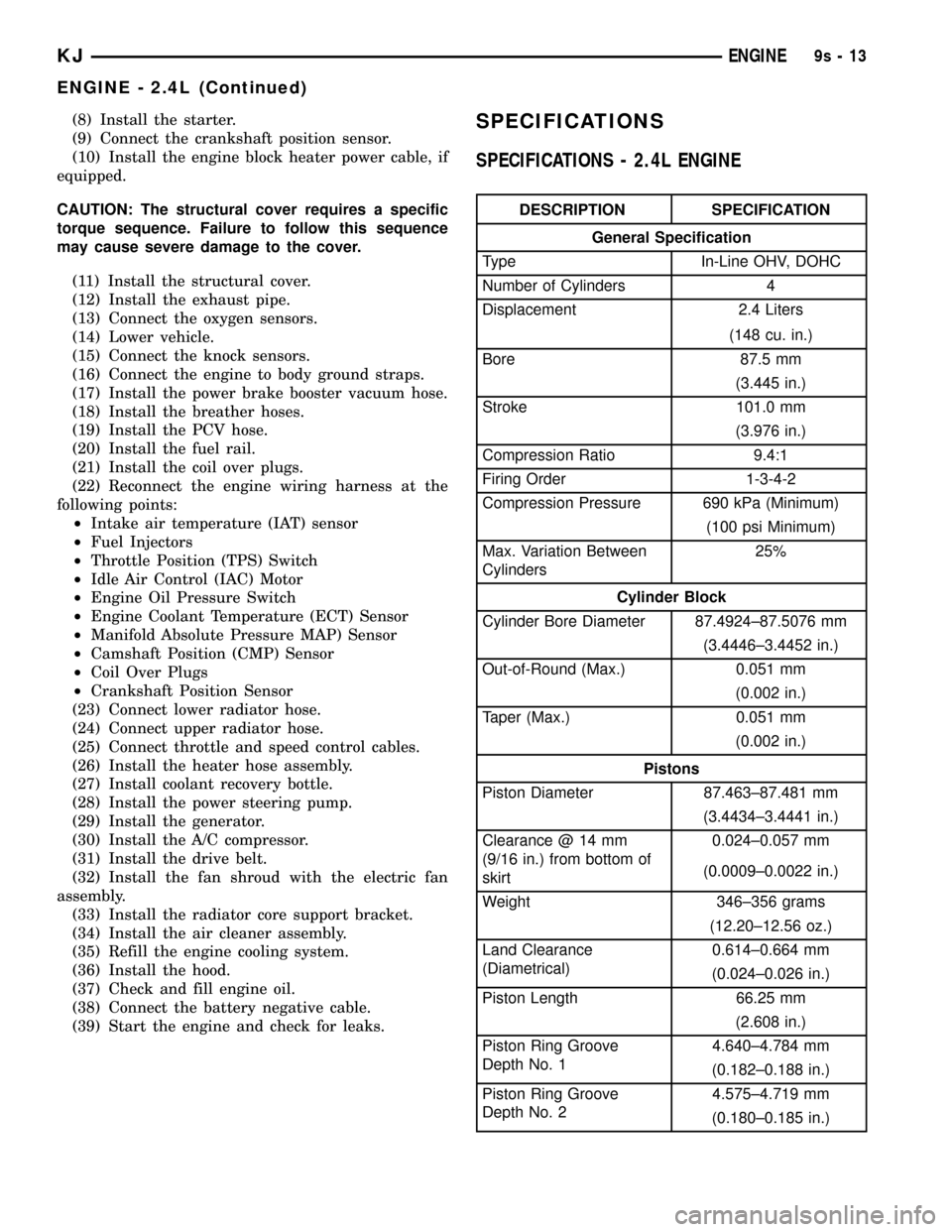
SPECIFICATIONS - 2.4L ENGINE
DESCRIPTION SPECIFICATION
General Specification
Type In-Line OHV, DOHC
Number of Cylinders 4
Displacement 2.4 Liters
(148 cu. in.)
Bore 87.5 mm
(3.445 in.)
Stroke 101.0 mm
(3.976 in.)
Compression Ratio 9.4:1
Firing Order 1-3-4-2
Compression Pressure 690 kPa (Minimum)
(100 psi Minimum)
Max. Variation Between
Cylinders25%
Cylinder Block
Cylinder Bore Diameter 87.4924±87.5076 mm
(3.4446±3.4452 in.)
Out-of-Round (Max.) 0.051 mm
(0.002 in.)
Taper (Max.) 0.051 mm
(0.002 in.)
Pistons
Piston Diameter 87.463±87.481 mm
(3.4434±3.4441 in.)
Clearance @ 14 mm
(9/16 in.) from bottom of
skirt0.024±0.057 mm
(0.0009±0.0022 in.)
Weight 346±356 grams
(12.20±12.56 oz.)
Land Clearance
(Diametrical)0.614±0.664 mm
(0.024±0.026 in.)
Piston Length 66.25 mm
(2.608 in.)
Piston Ring Groove
Depth No. 14.640±4.784 mm
(0.182±0.188 in.)
Piston Ring Groove
Depth No. 24.575±4.719 mm
(0.180±0.185 in.)
KJENGINE9s-13
ENGINE - 2.4L (Continued)
Page 1746 of 1803
COVER - REMOVAL, COWL TRIM.......23-157
COVER - REMOVAL, INSTRUMENT
PANEL TOP........................23-152
COVER - REMOVAL, STRUCTURAL........9-55
COVER(S) - DESCRIPTION, CYLINDER
HEAD...............................9-25
COVER(S) - INSTALLATION, CYLINDER
HEAD...........................9-26,9-34
COVER(S) - INSTALLATION, TIMING
BELT / CHAIN........................9-76
COVER(S) - REMOVAL, CYLINDER HEAD . . 9-25,
9-34
COVER(S) - REMOVAL, TIMING BELT /
CHAIN..............................9-74
COWL GRILLE - INSTALLATION........23-140
COWL GRILLE - REMOVAL............23-140
COWL TRIM COVER - INSTALLATION....23-157
COWL TRIM COVER - REMOVAL.......23-157
COWL WEATHERSTRIP - INSTALLATION . 23-185
COWL WEATHERSTRIP - REMOVAL.....23-185
COWL/PLENUM SEAL - INSTALLATION . . . 23-187
COWL/PLENUM SEAL - REMOVAL......23-187
COWL/PLENUM WINDOW BAFFLE SEAL -
INSTALLATION......................23-187
COWL/PLENUM WINDOW BAFFLE SEAL -
REMOVAL.........................23-187
CRADLE CROSSMEMBER -
INSTALLATION, ENGINE................13-6
CRADLE CROSSMEMBER - REMOVAL,
ENGINE.............................13-6
CRANKSHAFT - DESCRIPTION...........9-42
CRANKSHAFT - INSPECTION.............9-43
CRANKSHAFT - INSTALLATION...........9-43
CRANKSHAFT - REMOVAL..............9-43
CRANKSHAFT OIL SEAL - FRONT -
INSTALLATION........................9-47
CRANKSHAFT OIL SEAL - FRONT -
REMOVAL...........................9-46
CRANKSHAFT OIL SEAL - REAR -
INSTALLATION........................9-48
CRANKSHAFT OIL SEAL - REAR -
REMOVAL...........................9-48
CRANKSHAFT POSITION SENSOR -
DESCRIPTION.......................14-30
CRANKSHAFT POSITION SENSOR -
INSTALLATION.......................14-32
CRANKSHAFT POSITION SENSOR -
OPERATION.........................14-31
CRANKSHAFT POSITION SENSOR -
REMOVAL..........................14-31
CROSSMEMBER - INSTALLATION,
ENGINE CRADLE......................13-6
CROSSMEMBER - INSTALLATION,
RADIATOR.........................23-146
CROSSMEMBER - INSTALLATION, REAR . . . 13-7
CROSSMEMBER - REMOVAL, ENGINE
CRADLE.............................13-6
CROSSMEMBER - REMOVAL, RADIATOR . 23-146
CROSSMEMBER - REMOVAL, REAR.......13-7
CROSS-OVER PIPE - INSTALLATION.......11-3
CROSS-OVER PIPE - REMOVAL..........11-3
CRUISE INDICATOR - DESCRIPTION......8J-16
CRUISE INDICATOR - OPERATION.......8J-17
CURTAIN AIRBAG - DESCRIPTION, SIDE . . 8O-38
CURTAIN AIRBAG - INSTALLATION, SIDE . . 8O-41
CURTAIN AIRBAG - OPERATION, SIDE....8O-39
CURTAIN AIRBAG - REMOVAL, SIDE.....8O-40
CUSHION - FRONT - INSTALLATION,
SEAT .............................23-167
CUSHION - FRONT - INSTALLATION,
SEAT BACK........................23-167
CUSHION - FRONT - REMOVAL, SEAT . . . 23-167
CUSHION - FRONT - REMOVAL, SEAT
BACK.............................23-167
CUSHION - REAR - INSTALLATION, SEAT . 23-171
CUSHION - REAR - INSTALLATION, SEAT
BACK.............................23-170
CUSHION - REAR - REMOVAL, SEAT....23-171
CUSHION - REAR - REMOVAL, SEAT
BACK
.............................23-170
CUSHION COVER - FRONT -
INSTALLATION, SEAT
.................23-167
CUSHION COVER - FRONT - REMOVAL,
SEAT
.............................23-167
CUSHION SIDE SHIELDS -
INSTALLATION, SEAT
.................23-167
CUSHION SIDE SHIELDS - REMOVAL,
SEAT
.............................23-167CUSTOMER PREFERENCES - STANDARD
PROCEDURE, RKE TRANSMITTER........8N-8
CV JOINT/BOOT-INNER - INSTALLATION . . . 3-17
CV JOINT/BOOT-INNER - REMOVAL.......3-15
CV JOINT/BOOT-OUTER - INSTALLATION . . . 3-13
CV JOINT/BOOT-OUTER - REMOVAL.......3-12
CYLINDER - DESCRIPTION, MASTER......5-24
CYLINDER - INSPECTION, MASTER........6-9
CYLINDER - INSTALLATION, FLIP-UP
GLASS SUPPORT...................23-139
CYLINDER - INSTALLATION, LOCK......23-125,
23-138
CYLINDER - INSTALLATION, LOCK.......19-11
CYLINDER - INSTALLATION, MASTER.....5-25
CYLINDER - INSTALLATION, SUPPORT . . . 23-120
CYLINDER - OPERATION, MASTER........5-24
CYLINDER - REMOVAL, FLIP-UP GLASS
SUPPORT.........................23-139
CYLINDER - REMOVAL, LOCK....23-125,23-137
CYLINDER - REMOVAL, LOCK...........19-10
CYLINDER - REMOVAL, MASTER.........5-25
CYLINDER - REMOVAL, SUPPORT......23-120
CYLINDER BLEEDING - STANDARD
PROCEDURE, MASTER.................5-24
CYLINDER BORE HONING - STANDARD
PROCEDURE.........................9-39
CYLINDER COMBUSTION PRESSURE
LEAKAGE - DIAGNOSIS AND TESTING......9-8
CYLINDER COMPRESSION PRESSURE -
DIAGNOSIS AND TESTING...............9-8
CYLINDER FLUID LEVEL - STANDARD
PROCEDURES, MASTER................5-26
CYLINDER HEAD - DESCRIPTION.........9-30
CYLINDER HEAD COVER(S) -
DESCRIPTION........................9-25
CYLINDER HEAD COVER(S) -
INSTALLATION....................9-26,9-34
CYLINDER HEAD COVER(S) - REMOVAL . . . 9-25,
9-34
CYLINDER HEAD GASKET - DIAGNOSIS
AND TESTING....................9-19,9-30
CYLINDER LOCK SWITCH -
DESCRIPTION, DOOR..................8Q-9
CYLINDER LOCK SWITCH -
DESCRIPTION, TAILGATE...............8N-9
CYLINDER LOCK SWITCH - DIAGNOSIS
AND TESTING, DOOR.................8Q-10
CYLINDER LOCK SWITCH - DIAGNOSIS
AND TESTING, TAILGATE...............8N-9
CYLINDER LOCK SWITCH -
INSTALLATION, DOOR.................8Q-10
CYLINDER LOCK SWITCH -
INSTALLATION, TAILGATE..............8N-10
CYLINDER LOCK SWITCH - OPERATION,
DOOR.............................8Q-10
CYLINDER LOCK SWITCH - OPERATION,
TAILGATE...........................8N-9
CYLINDER LOCK SWITCH - REMOVAL,
DOOR.............................8Q-10
CYLINDER LOCK SWITCH - REMOVAL,
TAILGATE..........................8N-10
CYLINDER/POWER BOOSTER -
DIAGNOSIS AND TESTING, MASTER . . 5-21,5-24
CYLINDERS - ASSEMBLY, WHEEL.........5-29
CYLINDERS - CLEANING, WHEEL.........5-28
CYLINDERS - DISASSEMBLY, WHEEL......5-28
CYLINDERS - INSPECTION, WHEEL.......5-29
CYLINDERS - INSTALLATION, WHEEL
.....5-29
CYLINDERS - REMOVAL, WHEEL
.........5-28
DAMAGED OR WORN THREADS -
STANDARD PROCEDURE, REPAIR
.........9-9
DAMPER - INSTALLATION, VIBRATION
.....9-55
DAMPER - REMOVAL, VIBRATION
........9-54
DATA LINK CONNECTOR - DESCRIPTION
. . 8E-10
DATA LINK CONNECTOR - OPERATION
....8E-10
DAYTIME RUNNING LAMP RELAY -
DESCRIPTION
.......................8L-20
DAYTIME RUNNING LAMP RELAY -
INSTALLATION
.......................8L-21
DAYTIME RUNNING LAMP RELAY -
OPERATION
.........................8L-20
DAYTIME RUNNING LAMP RELAY -
REMOVAL
..........................8L-21
DECOUPLER - DIAGNOSIS AND
TESTING, GENERATOR
................8F-27
DECOUPLER PULLEY - DESCRIPTION,
GENERATOR
........................8F-26DECOUPLER PULLEY - INSTALLATION,
GENERATOR........................8F-30
DECOUPLER PULLEY - OPERATION,
GENERATOR........................8F-27
DECOUPLER PULLEY - REMOVAL,
GENERATOR........................8F-27
DEFINITION - DESCRIPTION, TRIP.......25-19
DEFLECTOR - INSTALLATION, WIND.....23-180
DEFLECTOR - REMOVAL, WIND........23-180
DEFOGGER - DESCRIPTION, REAR
WINDOW............................8G-3
DEFOGGER - OPERATION, REAR
WINDOW............................8G-3
DEFOGGER FUNCTION - DIAGNOSIS AND
TESTING, REAR HVAC CONTROL
ASSEMBLY WINDOW..................8G-9
DEFOGGER GRID - DESCRIPTION, REAR
WINDOW............................8G-5
DEFOGGER GRID - DIAGNOSIS AND
TESTING, REAR WINDOW..............8G-5
DEFOGGER GRID - OPERATION, REAR
WINDOW............................8G-5
DEFOGGER RELAY - DESCRIPTION,
REAR WINDOW.......................8G-6
DEFOGGER RELAY - DIAGNOSIS AND
TESTING, REAR WINDOW..............8G-6
DEFOGGER RELAY - INSTALLATION,
REAR WINDOW.......................8G-7
DEFOGGER RELAY - OPERATION, REAR
WINDOW............................8G-6
DEFOGGER RELAY - REMOVAL, REAR
WINDOW............................8G-7
DEFOGGER SWITCH - DESCRIPTION,
REAR WINDOW.......................8G-8
DEFOGGER SWITCH - DIAGNOSIS AND
TESTING, REAR WINDOW..............8G-8
DEFOGGER SWITCH - OPERATION, REAR
WINDOW............................8G-8
DEFOGGER SYSTEM - DIAGNOSIS AND
TESTING, REAR WINDOW..............8G-4
DEFROST DOO - INSTALLATION, FLOOR . . 24-37
DEFROST DOOR - REMOVAL...........24-35
DEFROST DOOR - REMOVAL, FLOOR.....24-36
DEFROST DOOR ACTUATOR -
INSTALLATION, FLOOR................24-25
DEFROST DOOR ACTUATOR - REMOVAL,
FLOOR.............................24-24
DEFROST DUCT/DEMISTER ADAPTOR -
REMOVAL..........................24-32
DEFROST/DEMISTER DUCT -
INSTALLATION.......................24-32
DELIVERY - DESCRIPTION, FUEL.........14-2
DELIVERY - OPERATION, FUEL...........14-3
DEMAGNETIZING - STANDARD
PROCEDURE, COMPASS...............8M-2
DEMISTER OUTLETS - DESCRIPTION.....24-29
DEPLOYMENT - STANDARD
PROCEDURE, SERVICE AFTER A
SUPPLEMENTAL RESTRAINT............8O-6
DETECTION PUMP - DESCRIPTION, LEAK . 25-27
DETECTION PUMP - INSTALLATION,
LEAK..............................25-28
DETECTION PUMP - OPERATION, LEAK . . . 25-28
DETECTION PUMP - REMOVAL, LEAK....25-28
DEVICES - STANDARD PROCEDURE,
ELECTROSTATIC DISCHARGE (ESD)
SENSITIVE........................8W-01-8
DIAGNOSIS CHART - DIAGNOSIS AND
TESTING, COOLING SYSTEM.............7-6
DIAGNOSIS, DIAGNOSIS AND TESTING -
WATER DRAINAGE AND WIND NOISE . . . 23-176
DIAGNOSTIC PROCEDURES, DIAGNOSIS
AND TESTING......................23-176
DIAGNOSTIC TROUBLE CODES -
DESCRIPTION........................25-2
DIAGNOSTICS (OBD) - DIAGNOSIS AND
TESTING, ON-BOARD...................7-3
DIAGRAMS - DESCRIPTION, HOW TO
USE WIRING......................8W-01-1
DIAGRAMS - HYDRAULIC SCHEMATICS,
SCHEMATICS.......................21-100
DIESEL - TORQUE, EXCEPT.............8F-23
DIFFERENTIAL - ASSEMBLY
........3-105,3-41
DIFFERENTIAL - DISASSEMBLY
.....3-105,3-41
DIFFERENTIAL - INSTALLATION
. 3-105,3-42,3-73
DIFFERENTIAL - REMOVAL
.....3-104,3-40,3-71
DIFFERENTIAL - TRAC-LOK - ASSEMBLY
. . 3-109,
3-77
KJINDEX 7
Description Group-Page Description Group-Page Description Group-Page
Page 1771 of 1803
COOLANT TEMPERATURE SENSOR -
OPERATION, ENGINE...................7-21
COOLANT TEMPERATURE SENSOR -
REMOVAL, ENGINE....................7-21
COOLER - DESCRIPTION, TRANS.........7-30
COOLERS AND TUBES - STANDARD
PROCEDURE, FLUSHING................7-30
COOLING, SPECIAL TOOLS..............7-13
COOLING SYSTEM - OPERATION..........7-2
COOLING SYSTEM - REVERSE
FLUSHING - STANDARD PROCEDURE.....7-12
COOLING SYSTEM - STANDARD
PROCEDURE, DRAINING................7-11
COOLING SYSTEM - STANDARD
PROCEDURE, REFILLING................7-11
COOLING SYSTEM 2.4L ENGINE -
DESCRIPTION.........................7-1
COOLING SYSTEM DIAGNOSIS CHART -
DIAGNOSIS AND TESTING...............7-5
COOLING SYSTEM LEAKS - DIAGNOSIS
AND TESTING.........................7-2
CORE AND OIL GALLERY PLUGS -
STANDARD PROCEDURE, ENGINE.........9-9
COVER - CLEANING, CYLINDER HEAD.....9-26
COVER - INSPECTION, CYLINDER HEAD . . . 9-26
COVER - INSTALLATION, CYLINDER
HEAD...............................9-26
COVER - REMOVAL, CYLINDER HEAD.....9-26
COVER(S) - INSTALLATION, TIMING
BELT ...............................9-53
COVER(S) - REMOVAL, TIMING BELT......9-53
CRANKSHAFT - DESCRIPTION...........9-32
CRANKSHAFT - INSPECTION.............9-34
CRANKSHAFT - INSTALLATION...........9-34
CRANKSHAFT - OPERATION.............9-33
CRANKSHAFT - REMOVAL..............9-33
CRANKSHAFT END PLAY - STANDARD
PROCEDURE.........................9-33
CRANKSHAFT OIL SEAL - FRONT -
INSTALLATION........................9-37
CRANKSHAFT OIL SEAL - FRONT -
REMOVAL...........................9-37
CRANKSHAFT OIL SEAL - REAR -
INSTALLATION........................9-39
CRANKSHAFT OIL SEAL - REAR -
REMOVAL...........................9-38
CRANKSHAFT SPROCKET -
INSTALLATION........................9-56
CRANKSHAFT SPROCKET - REMOVAL.....9-55
CROSS-OVER PIPE - INSTALLATION.......11-4
CROSS-OVER PIPE - REMOVAL..........11-4
CYLINDER BORE FITTING - STANDARD
PROCEDURE, PISTON TO...............9-30
CYLINDER BORE HONING - STANDARD
PROCEDURE.........................9-31
CYLINDER COMBUSTION PRESSURE
LEAKAGE TEST - DIAGNOSIS AND
TESTING.............................9-3
CYLINDER COMPRESSION PRESSURE
TEST - DIAGNOSIS AND TESTING.........9-3
CYLINDER HEAD - CLEANING............9-20
CYLINDER HEAD - DESCRIPTION.........9-19
CYLINDER HEAD - INSPECTION..........9-21
CYLINDER HEAD - INSTALLATION........9-21
CYLINDER HEAD - OPERATION...........9-19
CYLINDER HEAD - REMOVAL............9-20
CYLINDER HEAD COVER - CLEANING......9-26
CYLINDER HEAD COVER - INSPECTION....9-26
CYLINDER HEAD COVER -
INSTALLATION
........................9-26
CYLINDER HEAD COVER - REMOVAL
......9-26
CYLINDER HEAD GASKET - DIAGNOSIS
AND TESTING
........................9-19
CYLINDER HEAD OFF - INSTALLATION
.....9-28
CYLINDER HEAD OFF - REMOVAL
........9-27
CYLINDER HEAD ON - INSTALLATION
.....9-28
CYLINDER HEAD ON - REMOVAL
.........9-27
DAMAGED OR WORN THREADS -
STANDARD PROCEDURE, REPAIR OF
.......9-9
DAMPER - INSTALLATION, VIBRATION
.....9-43
DAMPER - REMOVAL, VIBRATION
........9-43
DAYTIME RUNNING LAMP RELAY -
DESCRIPTION
.......................8L-20
DAYTIME RUNNING LAMP RELAY -
INSTALLATION
.......................8L-21
DAYTIME RUNNING LAMP RELAY -
OPERATION
.........................8L-20DAYTIME RUNNING LAMP RELAY -
REMOVAL..........................8L-21
DESCRIPTION - OPERATION.............7-20
DESCRIPTION, BACKUP LAMP SWITCH . . . 8L-15
DESCRIPTION, BALANCE SHAFT..........9-59
DESCRIPTION, BRAKE LAMP SWITCH....8L-16
DESCRIPTION, CAMSHAFT(S)............9-23
DESCRIPTION, CATALYTIC CONVERTER....11-2
DESCRIPTION, COMBINATION FLASHER . . . 8L-19
DESCRIPTION, COOLANT RECOVERY
PRESS CONTAINER....................7-20
DESCRIPTION, COOLING SYSTEM 2.4L
ENGINE..............................7-1
DESCRIPTION, CRANKSHAFT............9-32
DESCRIPTION, CYLINDER HEAD..........9-19
DESCRIPTION, DAYTIME RUNNING
LAMP RELAY........................8L-20
DESCRIPTION, ENGINE - 2.4L.............9-3
DESCRIPTION, ENGINE BLOCK...........9-30
DESCRIPTION, ENGINE BLOCK HEATER -
2.4L................................7-20
DESCRIPTION, ENGINE COOLANT.........7-19
DESCRIPTION, ENGINE COOLANT
TEMPERATURE SENSOR................7-21
DESCRIPTION, ENGINE MOUNTING.......9-44
DESCRIPTION, EXHAUST MANIFOLD......9-53
DESCRIPTION, EXHAUST SYSTEM........11-1
DESCRIPTION, FRONT FOG LAMP RELAY . . 8L-22
DESCRIPTION, HAZARD SWITCH........8L-28
DESCRIPTION, HEADLAMP HIGH BEAM
RELAY.............................8L-33
DESCRIPTION, HEADLAMP LEVELING
MOTOR............................8L-35
DESCRIPTION, HEADLAMP LEVELING
SWITCH............................8L-37
DESCRIPTION, HEADLAMP LOW BEAM
RELAY.............................8L-39
DESCRIPTION, HEAT SHIELDS...........11-4
DESCRIPTION, HOAT COOLANT..........7-18
DESCRIPTION, HOSE CLAMPS............7-1
DESCRIPTION, INTAKE MANIFOLD........9-51
DESCRIPTION, INTAKE/EXHAUST VALVES
& SEATS ............................9-27
DESCRIPTION, LAMP BAR.............8L-65
DESCRIPTION, LAMP BAR SWITCH......8L-67
DESCRIPTION, LAMPS/LIGHTING -
EXTERIOR...........................8L-2
DESCRIPTION, LUBRICATION............9-46
DESCRIPTION, MUFFLER...............11-4
DESCRIPTION, MULTI-FUNCTION
SWITCH............................8L-46
DESCRIPTION, OIL FILTER..............9-47
DESCRIPTION, OIL PRESSURE
SENSOR/SWITCH.....................9-48
DESCRIPTION, PARK LAMP RELAY.......8L-54
DESCRIPTION, PISTON & CONNECTING
ROD................................9-40
DESCRIPTION, RADIATOR...............7-22
DESCRIPTION, RADIATOR FAN -
ELECTRIC...........................7-26
DESCRIPTION, RADIATOR PRESSURE
CAP ................................7-25
DESCRIPTION, REAR FOG LAMP RELAY . . . 8L-56
DESCRIPTION, TRAILER TOW RELAY.....8L-62
DESCRIPTION, TRAILER TOW WIRING....8L-64
DESCRIPTION, TRANS COOLER..........7-30
DESCRIPTION, WATER PUMP - 2.4L......7-27
DIAGNOSIS - DIAGNOSIS AND TESTING,
LASH ADJUSTER (TAPPET) NOISE........9-28
DIAGNOSIS - DIAGNOSIS AND TESTING,
SERPENTINE DRIVE BELT...............7-15
DIAGNOSIS - PERFORMANCE -
DIAGNOSIS AND TESTING, ENGINE........9-5
DIAGNOSIS AND TESTING, BACKUP
LAMP SWITCH......................8L-15
DIAGNOSIS AND TESTING, BRAKE LAMP
SWITCH............................8L-17
DIAGNOSIS AND TESTING, COOLING
SYSTEM DIAGNOSIS CHART
..............7-5
DIAGNOSIS AND TESTING, COOLING
SYSTEM LEAKS
........................7-2
DIAGNOSIS AND TESTING, CYLINDER
COMBUSTION PRESSURE LEAKAGE
TEST
................................9-3
DIAGNOSIS AND TESTING, CYLINDER
COMPRESSION PRESSURE TEST
..........9-3
DIAGNOSIS AND TESTING, CYLINDER
HEAD GASKET
........................9-19DIAGNOSIS AND TESTING, ENGINE........9-5
DIAGNOSIS AND TESTING, ENGINE
DIAGNOSIS - PERFORMANCE.............9-5
DIAGNOSIS AND TESTING, ENGINE
MECHANICAL.........................9-7
DIAGNOSIS AND TESTING, ENGINE OIL
LEAK INSPECTION......................9-4
DIAGNOSIS AND TESTING, ENGINE OIL
PRESSURE CHECKING.................9-46
DIAGNOSIS AND TESTING, EXHAUST
SYSTEM............................11-2
DIAGNOSIS AND TESTING, FRONT FOG
LAMP RELAY........................8L-23
DIAGNOSIS AND TESTING, HEADLAMP
HIGH BEAM RELAY...................8L-34
DIAGNOSIS AND TESTING, HEADLAMP
LEVELING SWITCH...................8L-37
DIAGNOSIS AND TESTING, HEADLAMP
LOW BEAM RELAY...................8L-40
DIAGNOSIS AND TESTING, INTAKE
MANIFOLD LEAKS.....................9-51
DIAGNOSIS AND TESTING, LAMP BAR....8L-65
DIAGNOSIS AND TESTING, LAMPS/
LIGHTING - EXTERIOR.................8L-7
DIAGNOSIS AND TESTING, LASH
ADJUSTER (TAPPET) NOISE
DIAGNOSIS..........................9-28
DIAGNOSIS AND TESTING, MULTI-
FUNCTION SWITCH...................8L-50
DIAGNOSIS AND TESTING, ON-BOARD
DIAGNOSTICS (OBD)....................7-2
DIAGNOSIS AND TESTING, PARK LAMP
RELAY.............................8L-55
DIAGNOSIS AND TESTING,
PRELIMINARY CHECKS..................7-2
DIAGNOSIS AND TESTING, RADIATOR
PRESSURE CAP.......................7-25
DIAGNOSIS AND TESTING, REAR FOG
LAMP RELAY........................8L-57
DIAGNOSIS AND TESTING, SERPENTINE
DRIVE BELT DIAGNOSIS................7-15
DIAGNOSIS AND TESTING, TRAILER
TOW RELAY.........................8L-62
DIAGNOSIS CHART - DIAGNOSIS AND
TESTING, COOLING SYSTEM.............7-5
DIAGNOSTICS (OBD) - DIAGNOSIS AND
TESTING, ON-BOARD...................7-2
DISASSEMBLY, OIL PUMP...............9-49
DRAINING COOLING SYSTEM -
STANDARD PROCEDURE................7-11
DRIVE BELT DIAGNOSIS - DIAGNOSIS
AND TESTING, SERPENTINE.............7-15
ELECTRIC - DESCRIPTION, RADIATOR
FAN ................................7-26
ELECTRIC - INSTALLATION, RADIATOR
FAN ................................7-27
ELECTRIC - OPERATION, RADIATOR FAN . . . 7-26
ELECTRIC - REMOVAL, RADIATOR FAN....7-26
END PLAY - STANDARD PROCEDURE,
CRANKSHAFT........................9-33
END-PLAY - STANDARD PROCEDURE,
CAMSHAFT..........................9-23
ENGINE - 2.4L - DESCRIPTION............9-3
ENGINE - DESCRIPTION, COOLING
SYSTEM 2.4L.........................7-1
ENGINE - DIAGNOSIS AND TESTING.......9-5
ENGINE - INSTALLATION, 2.4L . . 7-14,7-17,7-22,
7-28
ENGINE - REMOVAL, 2.4L . . . 7-14,7-16,7-22,7-27
ENGINE - SPECIFICATIONS, 2.4L.........9-13
ENGINE - STANDARD PROCEDURE,
HYDROSTATIC LOCKED..................9-9
ENGINE ASSEMBLY - INSTALLATION......9-12
ENGINE ASSEMBLY - REMOVAL..........9-12
ENGINE BLOCK - DESCRIPTION..........9-30
ENGINE BLOCK HEATER - 2.4L -
DESCRIPTION........................7-20
ENGINE BLOCK HEATER - 2.4L -
OPERATION..........................7-20
ENGINE COOLANT - DESCRIPTION
........7-19
ENGINE COOLANT TEMPERATURE
SENSOR - DESCRIPTION
...............7-21
ENGINE COOLANT TEMPERATURE
SENSOR - INSTALLATION
...............7-22
ENGINE COOLANT TEMPERATURE
SENSOR - OPERATION
.................7-21
ENGINE COOLANT TEMPERATURE
SENSOR - REMOVAL
...................7-21
2 INDEXKJ
Description Group-Page Description Group-Page Description Group-Page