Remove rear seat JEEP LIBERTY 2002 KJ / 1.G Workshop Manual
[x] Cancel search | Manufacturer: JEEP, Model Year: 2002, Model line: LIBERTY, Model: JEEP LIBERTY 2002 KJ / 1.GPages: 1803, PDF Size: 62.3 MB
Page 95 of 1803
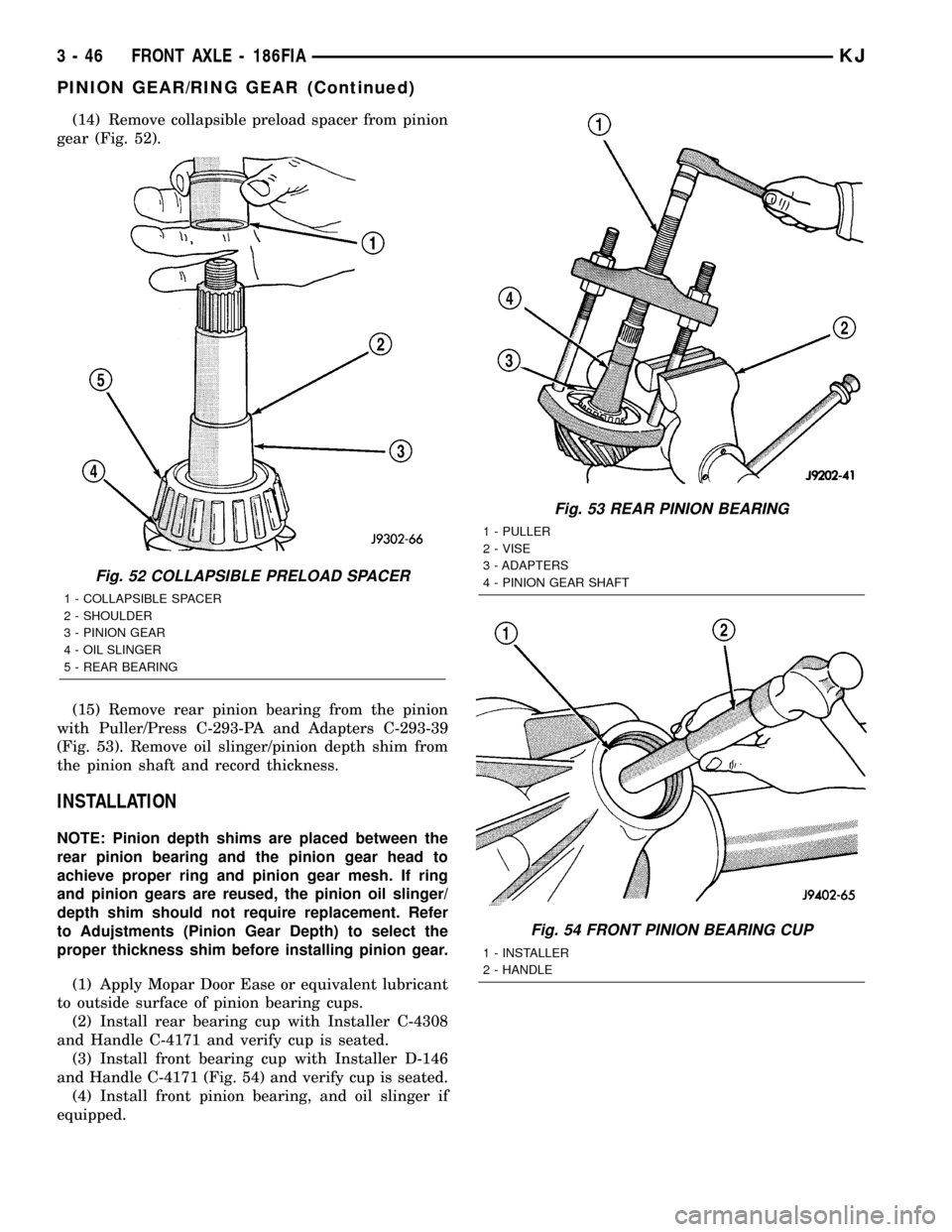
(14) Remove collapsible preload spacer from pinion
gear (Fig. 52).
(15) Remove rear pinion bearing from the pinion
with Puller/Press C-293-PA and Adapters C-293-39
(Fig. 53). Remove oil slinger/pinion depth shim from
the pinion shaft and record thickness.
INSTALLATION
NOTE: Pinion depth shims are placed between the
rear pinion bearing and the pinion gear head to
achieve proper ring and pinion gear mesh. If ring
and pinion gears are reused, the pinion oil slinger/
depth shim should not require replacement. Refer
to Adujstments (Pinion Gear Depth) to select the
proper thickness shim before installing pinion gear.
(1) Apply Mopar Door Ease or equivalent lubricant
to outside surface of pinion bearing cups.
(2) Install rear bearing cup with Installer C-4308
and Handle C-4171 and verify cup is seated.
(3) Install front bearing cup with Installer D-146
and Handle C-4171 (Fig. 54) and verify cup is seated.
(4) Install front pinion bearing, and oil slinger if
equipped.
Fig. 52 COLLAPSIBLE PRELOAD SPACER
1 - COLLAPSIBLE SPACER
2 - SHOULDER
3 - PINION GEAR
4 - OIL SLINGER
5 - REAR BEARING
Fig. 53 REAR PINION BEARING
1 - PULLER
2 - VISE
3 - ADAPTERS
4 - PINION GEAR SHAFT
Fig. 54 FRONT PINION BEARING CUP
1 - INSTALLER
2 - HANDLE
3 - 46 FRONT AXLE - 186FIAKJ
PINION GEAR/RING GEAR (Continued)
Page 103 of 1803
REMOVAL
(1) Raise and support the vehicle.
(2) Position a lift/jack under the axle and secure
axle to device.
(3) Remove wheels and tires.
(4) Mark propeller shaft and pinion yoke for
installation reference.
(5) Remove propeller shaft and suspend under the
vehicle.
(6) Remove brake drums, parking brake cables and
speed sensor from the axle.
(7) Disconnect the brake hose at the body junction
block.
(8) Remove brakes and backing plates.
(9) Remove vent hose from the axle shaft tube.
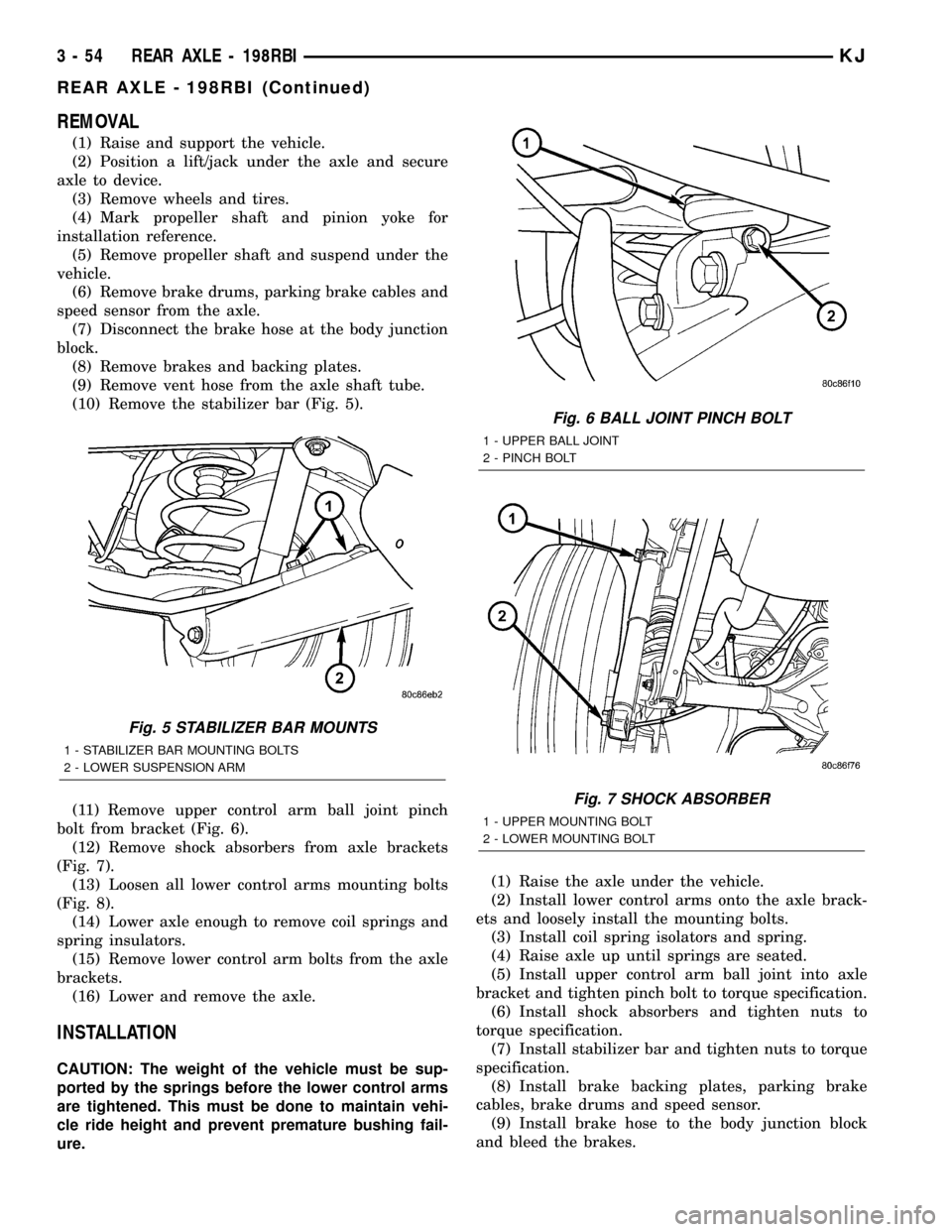
(10) Remove the stabilizer bar (Fig. 5).
(11) Remove upper control arm ball joint pinch
bolt from bracket (Fig. 6).
(12) Remove shock absorbers from axle brackets
(Fig. 7).
(13) Loosen all lower control arms mounting bolts
(Fig. 8).
(14) Lower axle enough to remove coil springs and
spring insulators.
(15) Remove lower control arm bolts from the axle
brackets.
(16) Lower and remove the axle.
INSTALLATION
CAUTION: The weight of the vehicle must be sup-
ported by the springs before the lower control arms
are tightened. This must be done to maintain vehi-
cle ride height and prevent premature bushing fail-
ure.(1) Raise the axle under the vehicle.
(2) Install lower control arms onto the axle brack-
ets and loosely install the mounting bolts.
(3) Install coil spring isolators and spring.
(4) Raise axle up until springs are seated.
(5) Install upper control arm ball joint into axle
bracket and tighten pinch bolt to torque specification.
(6) Install shock absorbers and tighten nuts to
torque specification.
(7) Install stabilizer bar and tighten nuts to torque
specification.
(8) Install brake backing plates, parking brake
cables, brake drums and speed sensor.
(9) Install brake hose to the body junction block
and bleed the brakes.
Fig. 5 STABILIZER BAR MOUNTS
1 - STABILIZER BAR MOUNTING BOLTS
2 - LOWER SUSPENSION ARM
Fig. 6 BALL JOINT PINCH BOLT
1 - UPPER BALL JOINT
2 - PINCH BOLT
Fig. 7 SHOCK ABSORBER
1 - UPPER MOUNTING BOLT
2 - LOWER MOUNTING BOLT
3 - 54 REAR AXLE - 198RBIKJ
REAR AXLE - 198RBI (Continued)
Page 107 of 1803
PRELOAD SHIM SELECTION
NOTE: It is difficult to salvage the differential side
bearings during the removal procedure. Install
replacement bearings if necessary.
(1) Remove side bearings from differential case.
(2) Install ring gear, if necessary, on differential
case and tighten bolts to specification.
(3) Install Dummy Bearings D-348 on differential
case.
(4) Install differential case in the housing.
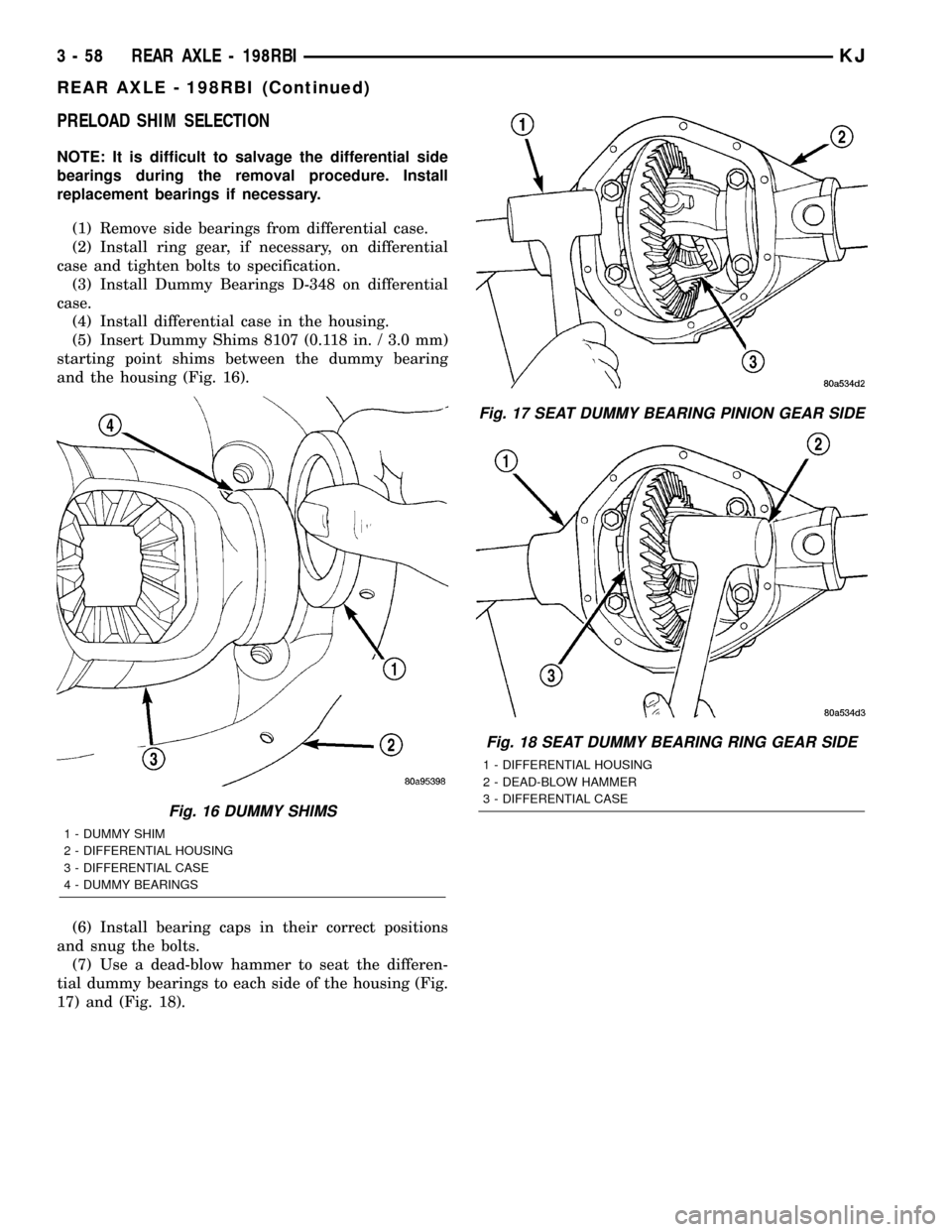
(5) Insert Dummy Shims 8107 (0.118 in. / 3.0 mm)
starting point shims between the dummy bearing
and the housing (Fig. 16).
(6) Install bearing caps in their correct positions
and snug the bolts.
(7) Use a dead-blow hammer to seat the differen-
tial dummy bearings to each side of the housing (Fig.
17) and (Fig. 18).
Fig. 16 DUMMY SHIMS
1 - DUMMY SHIM
2 - DIFFERENTIAL HOUSING
3 - DIFFERENTIAL CASE
4 - DUMMY BEARINGS
Fig. 17 SEAT DUMMY BEARING PINION GEAR SIDE
Fig. 18 SEAT DUMMY BEARING RING GEAR SIDE
1 - DIFFERENTIAL HOUSING
2 - DEAD-BLOW HAMMER
3 - DIFFERENTIAL CASE
3 - 58 REAR AXLE - 198RBIKJ
REAR AXLE - 198RBI (Continued)
Page 109 of 1803
(24) Rotate dial indicator out of the way on pilot
stud.
(25) Remove differential case and dummy bearings
from the housing.
(26) Install new side bearing cones and cups on
differential case.
(27) Install spreader W-129-B and some compo-
nents of Adapter Set 6987 on differential housing and
spread axle opening enough to receive differential
case.
(28) Place side bearing shims into the housing
against the axle tubes.
(29) Install differential case in the housing.
(30) Rotate the differential case several times to
seat the side bearings.
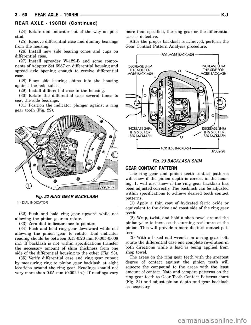
(31) Position the indicator plunger against a ring
gear tooth (Fig. 22).
(32) Push and hold ring gear upward while not
allowing the pinion gear to rotate.
(33) Zero dial indicator face to pointer.
(34) Push and hold ring gear downward while not
allowing the pinion gear to rotate. Dial indicator
reading should be between 0.13-0.20 mm (0.005-0.008
in.). If backlash is not within specifications transfer
the necessary amount of shim thickness from one
side of the differential housing to the other (Fig. 23).
(35) Verify differential case and ring gear runout
by measuring ring to pinion gear backlash at eight
locations around the ring gear. Readings should not
vary more than 0.05 mm (0.002 in.). If readings varymore than specified, the ring gear or the differential
case is defective.
After the proper backlash is achieved, perform the
Gear Contact Pattern Analysis procedure.
GEAR CONTACT PATTERN
The ring gear and pinion teeth contact patterns
will show if the pinion depth is correct in the hous-
ing. It will also show if the ring gear backlash has
been adjusted correctly. The backlash can be adjusted
within specifications to achieve desired tooth contact
patterns.
(1) Apply a thin coat of hydrated ferric oxide or
equivalent to the drive and coast side of the ring gear
teeth.
(2) Wrap, twist, and hold a shop towel around the
pinion yoke to increase the turning resistance of the
pinion. This will provide a more distinct contact pat-
tern.
(3) With a boxed end wrench on a ring gear bolt,
rotate the differential case one complete revolution in
both directions while a load is being applied from
shop towel.
The areas on the ring gear teeth with the greatest
degree of contact against the pinion teeth will
squeeze the compound to the areas with the least
amount of contact. Note and compare patterns on the
ring gear teeth to Gear Tooth Contact Patterns chart
(Fig. 24) and adjust pinion depth and gear backlash
as necessary.
Fig. 22 RING GEAR BACKLASH
1 - DIAL INDICATOR
Fig. 23 BACKLASH SHIM
3 - 60 REAR AXLE - 198RBIKJ
REAR AXLE - 198RBI (Continued)
Page 122 of 1803

(12) Remove differential from the housing. Ensure
that the differential bearing cups remain in position
on the differential bearings (Fig. 47).
(13) Remove bearing cups from the differential and
tag them to indicate their location.
(14) Remove differential case preload shims from
the housing and tag them to indicate their location.
(15) Remove spreader from housing.
INSTALLATION
NOTE: If differential bearings or differential case are
replaced, differential bearing preload shim require-
ments may change. Refer Adjustments (Differential
Bearing Preload and Gear Backlash) to determine
the proper shim selection.
(1) With Spreader W-129-B and adapters from
Adapter set 6987, position the adapters in the differ-
ential holes (Fig. 48). Install the hold-down clamps
and tighten the tool turnbuckle finger-tight.
(2) Install a Pilot Stud C-3288-B at the left side of
the differential housing. Attach Dial Indicator C-3339
to pilot stud. Load the indicator plunger against the
opposite side of the housing and zero the indicator.
(3) Spread the housing while measuring the dis-
tance with the dial indicator. Spread the housing
enough to install the differential case.
CAUTION: Do not spread over 0.38 mm (0.015 in). If
the housing is over±spread, it could be distorted or
damaged.
(4) Remove the dial indicator.(5) Install differential case in the housing (Fig. 49)
with bearing cups and preload shims in their original
locations. Tap the differential case to ensure the
bearings cups and shims are fully seated in the hous-
ing.
Fig. 47 DIFFERENTIAL CASE
1 - DIFFERENTIAL HOUSING
2 - DIFFERENTIAL CASE
3 - BEARING CUPSFig. 48 SPREADER LOCATION
1 - DIFFERENTIAL HOUSING
2 - ADAPTER
3 - SAFETY HOLD DOWN
4 - SPREADER
5 - TURNBUCKLE
Fig. 49 DIFFERENTIAL CASE
1 - DIFFERENTIAL HOUSING
2 - DIFFERENTIAL CASE
3 - BEARING CUPS
KJREAR AXLE - 198RBI 3 - 73
DIFFERENTIAL (Continued)
Page 127 of 1803
(3) Position assembled clutch disc packs on the
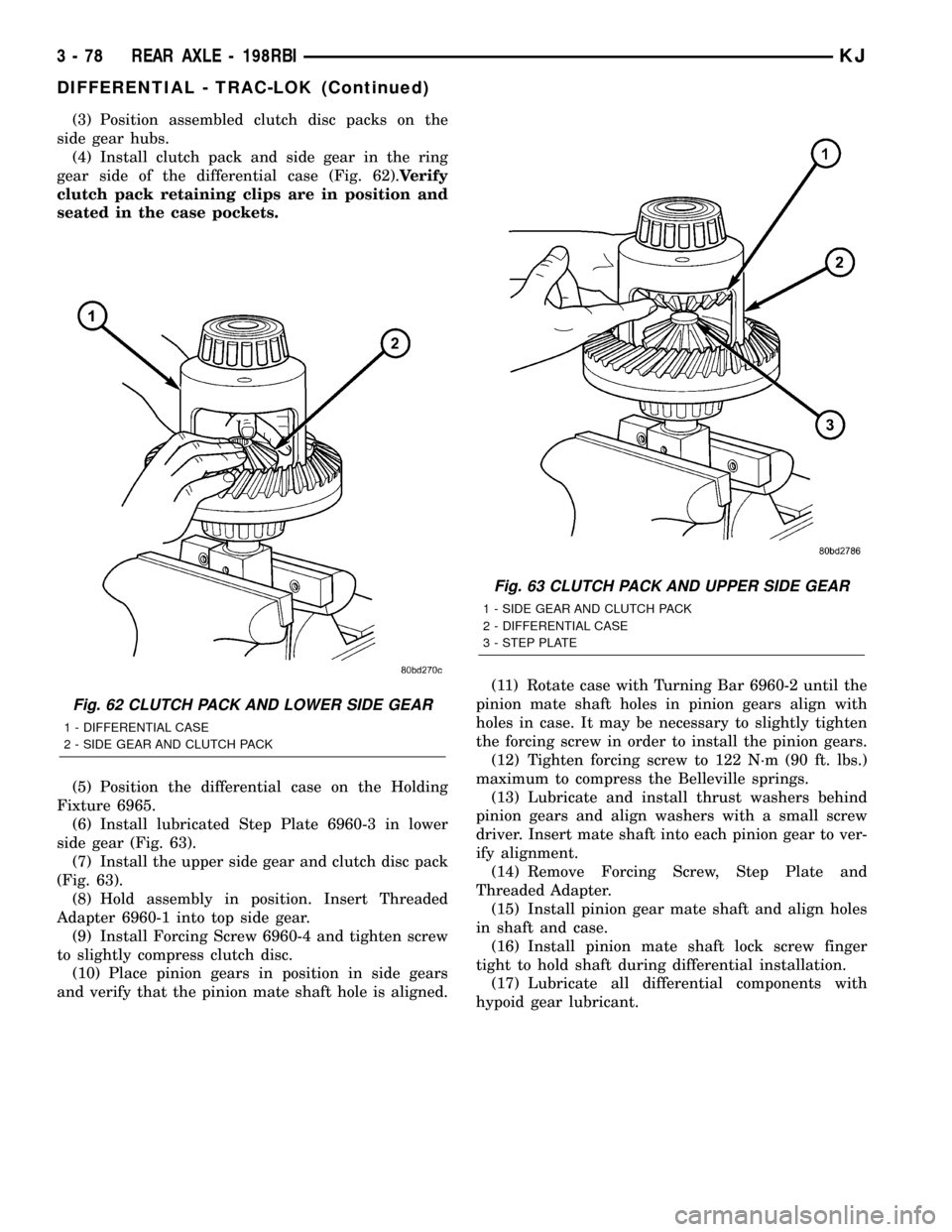
side gear hubs.
(4) Install clutch pack and side gear in the ring
gear side of the differential case (Fig. 62).Verify
clutch pack retaining clips are in position and
seated in the case pockets.
(5) Position the differential case on the Holding
Fixture 6965.
(6) Install lubricated Step Plate 6960-3 in lower
side gear (Fig. 63).
(7) Install the upper side gear and clutch disc pack
(Fig. 63).
(8) Hold assembly in position. Insert Threaded
Adapter 6960-1 into top side gear.
(9) Install Forcing Screw 6960-4 and tighten screw
to slightly compress clutch disc.
(10) Place pinion gears in position in side gears
and verify that the pinion mate shaft hole is aligned.(11) Rotate case with Turning Bar 6960-2 until the
pinion mate shaft holes in pinion gears align with
holes in case. It may be necessary to slightly tighten
the forcing screw in order to install the pinion gears.
(12) Tighten forcing screw to 122 N´m (90 ft. lbs.)
maximum to compress the Belleville springs.
(13) Lubricate and install thrust washers behind
pinion gears and align washers with a small screw
driver. Insert mate shaft into each pinion gear to ver-
ify alignment.
(14) Remove Forcing Screw, Step Plate and
Threaded Adapter.
(15) Install pinion gear mate shaft and align holes
in shaft and case.
(16) Install pinion mate shaft lock screw finger
tight to hold shaft during differential installation.
(17) Lubricate all differential components with
hypoid gear lubricant.
Fig. 62 CLUTCH PACK AND LOWER SIDE GEAR
1 - DIFFERENTIAL CASE
2 - SIDE GEAR AND CLUTCH PACK
Fig. 63 CLUTCH PACK AND UPPER SIDE GEAR
1 - SIDE GEAR AND CLUTCH PACK
2 - DIFFERENTIAL CASE
3 - STEP PLATE
3 - 78 REAR AXLE - 198RBIKJ
DIFFERENTIAL - TRAC-LOK (Continued)
Page 131 of 1803
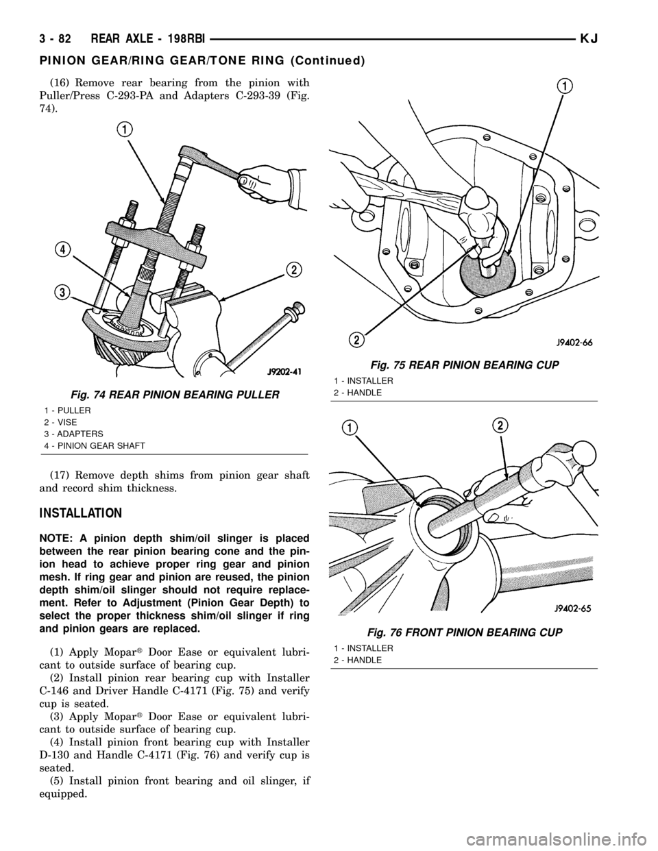
(16) Remove rear bearing from the pinion with
Puller/Press C-293-PA and Adapters C-293-39 (Fig.
74).
(17) Remove depth shims from pinion gear shaft
and record shim thickness.
INSTALLATION
NOTE: A pinion depth shim/oil slinger is placed
between the rear pinion bearing cone and the pin-
ion head to achieve proper ring gear and pinion
mesh. If ring gear and pinion are reused, the pinion
depth shim/oil slinger should not require replace-
ment. Refer to Adjustment (Pinion Gear Depth) to
select the proper thickness shim/oil slinger if ring
and pinion gears are replaced.
(1) Apply MopartDoor Ease or equivalent lubri-
cant to outside surface of bearing cup.
(2) Install pinion rear bearing cup with Installer
C-146 and Driver Handle C-4171 (Fig. 75) and verify
cup is seated.
(3) Apply MopartDoor Ease or equivalent lubri-
cant to outside surface of bearing cup.
(4) Install pinion front bearing cup with Installer
D-130 and Handle C-4171 (Fig. 76) and verify cup is
seated.
(5) Install pinion front bearing and oil slinger, if
equipped.
Fig. 74 REAR PINION BEARING PULLER
1 - PULLER
2 - VISE
3 - ADAPTERS
4 - PINION GEAR SHAFT
Fig. 75 REAR PINION BEARING CUP
1 - INSTALLER
2 - HANDLE
Fig. 76 FRONT PINION BEARING CUP
1 - INSTALLER
2 - HANDLE
3 - 82 REAR AXLE - 198RBIKJ
PINION GEAR/RING GEAR/TONE RING (Continued)
Page 140 of 1803
REMOVAL
(1) Raise and support the vehicle.
(2) Position a lift/jack under the axle and secure
axle to device.
(3) Remove wheels and tires.
(4) Mark propeller shaft and pinion yoke for
installation reference.
(5) Remove propeller shaft and suspend under the
vehicle.
(6) Remove brake drums, parking brake cables and
speed sensor from the axle.
(7) Disconnect the brake hose at the body junction
block.
(8) Remove brakes and backing plates.
(9) Remove vent hose from the axle shaft tube.
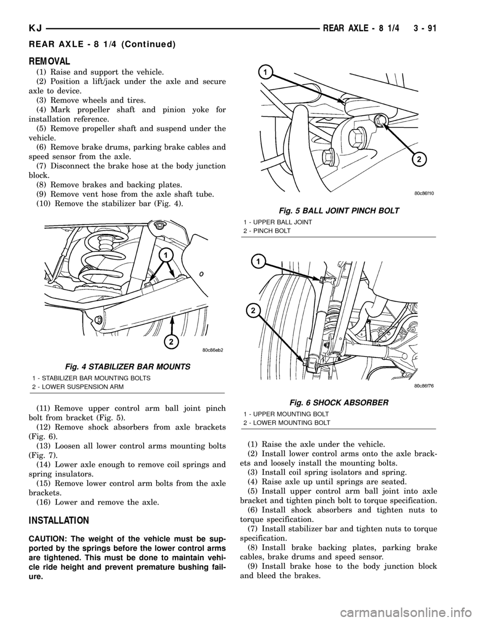
(10) Remove the stabilizer bar (Fig. 4).
(11) Remove upper control arm ball joint pinch
bolt from bracket (Fig. 5).
(12) Remove shock absorbers from axle brackets
(Fig. 6).
(13) Loosen all lower control arms mounting bolts
(Fig. 7).
(14) Lower axle enough to remove coil springs and
spring insulators.
(15) Remove lower control arm bolts from the axle
brackets.
(16) Lower and remove the axle.
INSTALLATION
CAUTION: The weight of the vehicle must be sup-
ported by the springs before the lower control arms
are tightened. This must be done to maintain vehi-
cle ride height and prevent premature bushing fail-
ure.(1) Raise the axle under the vehicle.
(2) Install lower control arms onto the axle brack-
ets and loosely install the mounting bolts.
(3) Install coil spring isolators and spring.
(4) Raise axle up until springs are seated.
(5) Install upper control arm ball joint into axle
bracket and tighten pinch bolt to torque specification.
(6) Install shock absorbers and tighten nuts to
torque specification.
(7) Install stabilizer bar and tighten nuts to torque
specification.
(8) Install brake backing plates, parking brake
cables, brake drums and speed sensor.
(9) Install brake hose to the body junction block
and bleed the brakes.
Fig. 4 STABILIZER BAR MOUNTS
1 - STABILIZER BAR MOUNTING BOLTS
2 - LOWER SUSPENSION ARM
Fig. 5 BALL JOINT PINCH BOLT
1 - UPPER BALL JOINT
2 - PINCH BOLT
Fig. 6 SHOCK ABSORBER
1 - UPPER MOUNTING BOLT
2 - LOWER MOUNTING BOLT
KJREAR AXLE - 8 1/4 3 - 91
REAR AXLE - 8 1/4 (Continued)
Page 150 of 1803
AXLE SHAFTS
REMOVAL
(1) Place the transmission in NEUTRAL and raise
and support vehicle.
(2) Remove wheel and tire assembly.
(3) Remove brake drum.
(4) Remove the housing cover and drain lubricant.
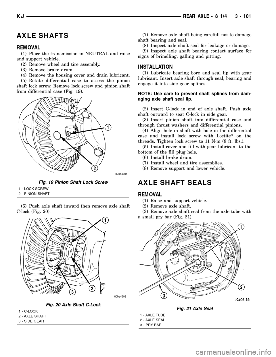
(5) Rotate differential case to access the pinion
shaft lock screw. Remove lock screw and pinion shaft
from differential case (Fig. 19).
(6) Push axle shaft inward then remove axle shaft
C-lock (Fig. 20).(7) Remove axle shaft being carefull not to damage
shaft bearing and seal.
(8) Inspect axle shaft seal for leakage or damage.
(9) Inspect axle shaft bearing contact surface for
signs of brinelling, galling and pitting.
INSTALLATION
(1) Lubricate bearing bore and seal lip with gear
lubricant. Insert axle shaft through seal, bearing and
engage it into side gear splines.
NOTE: Use care to prevent shaft splines from dam-
aging axle shaft seal lip.
(2) Insert C-lock in end of axle shaft. Push axle
shaft outward to seat C-lock in side gear.
(3) Insert pinion shaft into differential case and
through thrust washers and differential pinions.
(4) Align hole in shaft with hole in the differential
case and install lock screw with Loctiteton the
threads. Tighten lock screw to 11 N´m (8 ft. lbs.).
(5) Install cover and fill with gear lubricant to the
bottom of the fill plug hole.
(6) Install brake drum.
(7) Install wheel and tire assemblies.
(8) Remove support and lower vehicle.
AXLE SHAFT SEALS
REMOVAL
(1) Raise and support vehicle.
(2) Remove axle shaft.
(3) Remove axle shaft seal from the axle tube with
a small pry bar (Fig. 21).
Fig. 19 Pinion Shaft Lock Screw
1 - LOCK SCREW
2 - PINION SHAFT
Fig. 20 Axle Shaft C-Lock
1 - C-LOCK
2 - AXLE SHAFT
3 - SIDE GEARFig. 21 Axle Seal
1 - AXLE TUBE
2 - AXLE SEAL
3-PRYBAR
KJREAR AXLE - 8 1/4 3 - 101
Page 152 of 1803
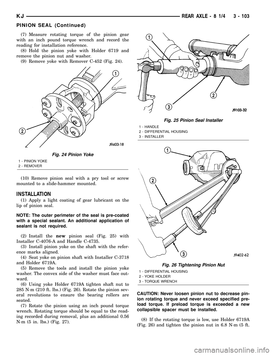
(7) Measure rotating torque of the pinion gear
with an inch pound torque wrench and record the
reading for installation reference.
(8) Hold the pinion yoke with Holder 6719 and
remove the pinion nut and washer.
(9) Remove yoke with Remover C-452 (Fig. 24).
(10) Remove pinion seal with a pry tool or screw
mounted to a slide-hammer mounted.
INSTALLATION
(1) Apply a light coating of gear lubricant on the
lip of pinion seal.
NOTE: The outer perimeter of the seal is pre-coated
with a special sealant. An additional application of
sealant is not required.
(2) Install thenewpinion seal (Fig. 25) with
Installer C-4076-A and Handle C-4735.
(3) Install pinion yoke on the shaft with the refer-
ence marks aligned.
(4) Seat yoke on pinion shaft with Installer C-3718
and Holder 6719A.
(5) Remove the tools and install the pinion yoke
washer. The convex side of the washer must face out-
ward.
(6) Using yoke Holder 6719A tighten shaft nut to
285 N´m (210 ft. lbs.) (Fig. 26). Rotate the pinion sev-
eral revolutions to ensure the bearing rollers are
seated.
(7) Rotate the pinion using an inch pound torque
wrench. Rotating torque should be equal to the read-
ing recorded during removal, plus an additional 0.56
N´m (5 in. lbs.) (Fig. 27).CAUTION: Never loosen pinion nut to decrease pin-
ion rotating torque and never exceed specified pre-
load torque. If preload torque is exceeded a new
collapsible spacer must be installed.
(8) If the rotating torque is low, use Holder 6719A
(Fig. 26) and tighten the pinion nut in 6.8 N´m (5 ft.
Fig. 24 Pinion Yoke
1 - PINION YOKE
2 - REMOVER
Fig. 25 Pinion Seal Installer
1 - HANDLE
2 - DIFFERENTIAL HOUSING
3 - INSTALLER
Fig. 26 Tightening Pinion Nut
1 - DIFFERENTIAL HOUSING
2 - YOKE HOLDER
3 - TORQUE WRENCH
KJREAR AXLE - 8 1/4 3 - 103
PINION SEAL (Continued)