Windows JEEP LIBERTY 2002 KJ / 1.G Workshop Manual
[x] Cancel search | Manufacturer: JEEP, Model Year: 2002, Model line: LIBERTY, Model: JEEP LIBERTY 2002 KJ / 1.GPages: 1803, PDF Size: 62.3 MB
Page 63 of 1803

(4) Rotate the inner race/hub in the cage (Fig. 11).
(5) Insert cage into the housing (Fig. 12). Rotate
the cage 90É into the housing (Fig. 13).
(6) Apply the lubricant included with the replace-
ment boot to the ball races. Spread the lubricant
equally between all the races.
(7) Tilt inner race/hub and cage and install the
balls (Fig. 14).
Fig. 11 CAGE AND INNER RACE/HUB
1 - CAGE WINDOWS
2 - SNAP RING
Fig. 12 BEARING CAGE AND HOUSING
1 - OUTER RACE
2 - BEARING CAGE WINDOW
3 - CV JOINT HOUSING
Fig. 13 CAGE AND INNER RACE/HUB
1 - C/V HOUSING
2 - BEARING HUB LARGE COUNTERBORE OUTWARD
3 - BOOT RETAINING SHOULDER
4 - BEARING HUB SMALL COUNTERBORE INWARD
5 - SLINGER
Fig. 14 BALL BEARING
1 - C/V HOUSING
2 - INNER RACE/HUB
3 - BEARING CAGE
4 - BEARING
3 - 14 HALF SHAFTKJ
CV JOINT/BOOT-OUTER (Continued)
Page 66 of 1803

INSTALLATION
(1) Apply a coat of grease supplied with the joint/
boot to the C/V joint components before assembling
them.
(2) Place new clamps on the new boot and slide
boot down the shaft.
(3) Slide cage onto the shaft (Fig. 22) with the
small diameter end towards the boot.
(4) Install the inner race onto the shaft (Fig. 23).
Pull on the race to verify snap ring has engaged.
(5) Align cage with the inner race and slide over
the race.
(6) Turn the cage 30É to align the cage windows
with the race (Fig. 24).
(7) Apply grease to the inner race and bearings
and install the bearings.
Fig. 22 BEARING CAGE
1 - SHAFT
2 - CAGE
3 - SMALL DIAMETER
4 - SNAP RING GROOVE
Fig. 23 INNER RACE
1 - INNER RACE
2 - CAGE
3 - SHAFT
Fig. 24 CAGE/INNER RACE
1 - CAGE
2 - INNER RACE
3 - SHAFT
4 - CAGE WINDOW
KJHALF SHAFT 3 - 17
CV JOINT/BOOT-INNER (Continued)
Page 604 of 1803

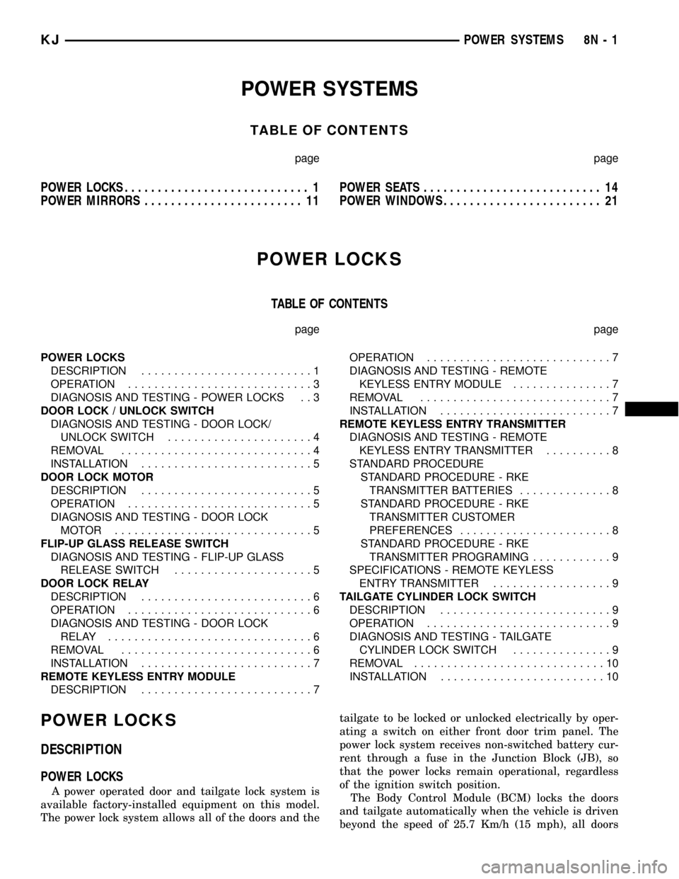
POWER SYSTEMS
TABLE OF CONTENTS
page page
POWER LOCKS............................ 1
POWER MIRRORS........................ 11POWER SEATS........................... 14
POWER WINDOWS........................ 21
POWER LOCKS
TABLE OF CONTENTS
page page
POWER LOCKS
DESCRIPTION..........................1
OPERATION............................3
DIAGNOSIS AND TESTING - POWER LOCKS . . 3
DOOR LOCK / UNLOCK SWITCH
DIAGNOSIS AND TESTING - DOOR LOCK/
UNLOCK SWITCH......................4
REMOVAL.............................4
INSTALLATION..........................5
DOOR LOCK MOTOR
DESCRIPTION..........................5
OPERATION............................5
DIAGNOSIS AND TESTING - DOOR LOCK
MOTOR ..............................5
FLIP-UP GLASS RELEASE SWITCH
DIAGNOSIS AND TESTING - FLIP-UP GLASS
RELEASE SWITCH.....................5
DOOR LOCK RELAY
DESCRIPTION..........................6
OPERATION............................6
DIAGNOSIS AND TESTING - DOOR LOCK
RELAY...............................6
REMOVAL.............................6
INSTALLATION..........................7
REMOTE KEYLESS ENTRY MODULE
DESCRIPTION..........................7OPERATION............................7
DIAGNOSIS AND TESTING - REMOTE
KEYLESS ENTRY MODULE...............7
REMOVAL.............................7
INSTALLATION..........................7
REMOTE KEYLESS ENTRY TRANSMITTER
DIAGNOSIS AND TESTING - REMOTE
KEYLESS ENTRY TRANSMITTER..........8
STANDARD PROCEDURE
STANDARD PROCEDURE - RKE
TRANSMITTER BATTERIES..............8
STANDARD PROCEDURE - RKE
TRANSMITTER CUSTOMER
PREFERENCES.......................8
STANDARD PROCEDURE - RKE
TRANSMITTER PROGRAMING............9
SPECIFICATIONS - REMOTE KEYLESS
ENTRY TRANSMITTER..................9
TAILGATE CYLINDER LOCK SWITCH
DESCRIPTION..........................9
OPERATION............................9
DIAGNOSIS AND TESTING - TAILGATE
CYLINDER LOCK SWITCH...............9
REMOVAL.............................10
INSTALLATION.........................10
POWER LOCKS
DESCRIPTION
POWER LOCKS
A power operated door and tailgate lock system is
available factory-installed equipment on this model.
The power lock system allows all of the doors and thetailgate to be locked or unlocked electrically by oper-
ating a switch on either front door trim panel. The
power lock system receives non-switched battery cur-
rent through a fuse in the Junction Block (JB), so
that the power locks remain operational, regardless
of the ignition switch position.
The Body Control Module (BCM) locks the doors
and tailgate automatically when the vehicle is driven
beyond the speed of 25.7 Km/h (15 mph), all doors
KJPOWER SYSTEMS 8N - 1
Page 624 of 1803

POWER WINDOWS
TABLE OF CONTENTS
page page
POWER WINDOWS
DESCRIPTION.........................21
OPERATION...........................21
DIAGNOSIS AND TESTING - POWER
WINDOWS...........................21
WINDOW MOTOR
REMOVAL.............................22WINDOW SWITCH
DIAGNOSIS AND TESTING - WINDOW
SWITCH............................22
REMOVAL.............................23
INSTALLATION.........................23
POWER WINDOWS
DESCRIPTION
The power window system allows each of the door
windows to be raised and lowered electrically by
actuating a switch on the center console. A master
switch on the front of the center console allows the
driver to raise or lower each of the passenger door
windows and to lock out the individual switches on
the rear of the center console from operation. The
power window system receives battery feed through
fuse 13 in the Power Distribution Center (PDC), only
when the ignition switch is in the RUN or ACCES-
SORY position.
OPERATION
WINDOW SWITCH
The power window switches control the battery
and ground feeds to the power window motors. Both
of the rear door power window switches receive their
battery and ground feeds through the circuitry of the
front window switch. When the power window lock-
out switch is in the Lock position, the battery feed
for the rear door window switches is interrupted.
WINDOW MOTOR
Front door window lift motors use permanent type
magnets. The B+ and ground applied at the motor
terminal pins will cause the motor to rotate in one
direction. Reversing current through the motor ter-
minals will cause the motor to rotate in the opposite
direction.
Refer to the appropriate wiring information. The
wiring information includes wiring diagrams, proper
wire and connector repair procedures, details of wire
harness routing and retention, connector pin-out
information and location views for the various wire
harness connectors, splices and grounds.
DIAGNOSIS AND TESTING - POWER
WINDOWS
WIRING VOLTAGE TEST
The following wiring test determines whether or
not voltage is continuous through the body harness
to the front switch.
(1) Remove the power window switch and bezel
(Refer to 8 - ELECTRICAL/POWER WINDOWS/
POWER WINDOW SWITCH - REMOVAL).
(2) Disconnect wire connector from back of power
window switch.
(3) Switch ignition to the ON position.
(4) Connect the clip end of a 12 volt test light to
Pin 14 of the window switch harness connector.
Touch the test light probe to Pin 10.
²If the test light illuminates, the wiring circuit
between the battery and switch is OK.
²If the lamp does not illuminate, first check fuse
13 in the Power Distribution Center (PDC). If fuse 13
is OK, then check for a broken wire.
Refer to the appropriate wiring information. The
wiring information includes wiring diagrams, proper
wire and connector repair procedures, details of wire
harness routing and retention, connector pin-out
information and location views for the various wire
harness connectors, splices and grounds.
POWER WINDOW MOTOR TEST
If the power window motor is receiving proper cur-
rent and ground and does not operate, proceed with
motor test. Refer to the appropriate wiring informa-
tion. The wiring information includes wiring dia-
grams, proper wire and connector repair procedures,
details of wire harness routing and retention, connec-
tor pin-out information and location views for the
various wire harness connectors, splices and grounds.
(1) Remove front door trim panel as necessary to
gain access to power window motor wire connector
KJPOWER WINDOWS 8N - 21
Page 625 of 1803

(Refer to 23 - BODY/DOOR - FRONT/TRIM PANEL -
REMOVAL).
(2) Disconnect power window motor wire connector
from door harness.
(3) Using two jumper wires, connect one to a bat-
tery (+) source and the other to a good ground (-).
(4) Connect the Negative (-) jumper probe to one of
the motor connector terminals.
(5) Momentarily touch the Positive (+) jumper
probe to the other motor connector terminal.
When positive probe is connected the motor should
rotate in one direction to either move window up or
down. If window is all the way up or down the motor
will grunt and the inner door panel will flex when
actuated in that one direction.
(6) Reverse jumper probes at the motor connector
terminals and window should now move in opposite
direction. If window does not move or grunt, replace
the motor.
If window moved completely up or down, reverse
the jumper probes and cycle window to the opposite
position to verify full operation.
If motor grunts and does not move, verify that reg-
ulator is not binding.
WINDOW MOTOR
REMOVAL
The window motor is incorporated into the window
regulator assembly. If the window motor requires
replacement, the window regulator must be replaced.
(Refer to 23 - BODY/DOOR - FRONT/WINDOW
REGULATOR - REMOVAL) or (Refer to 23 - BODY/
DOORS - REAR/WINDOW REGULATOR - REMOV-
AL).
WINDOW SWITCH
DIAGNOSIS AND TESTING - WINDOW SWITCH
(1) Remove the switch to be tested (Refer to 8 -
ELECTRICAL/POWER WINDOWS/POWER WIN-
DOW SWITCH - REMOVAL).
(2) Using an ohmmeter, Test front switch for con-
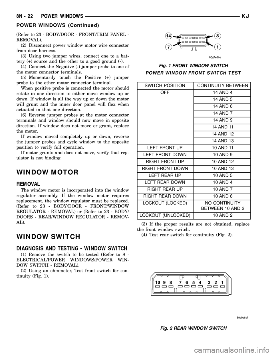
tinuity (Fig. 1).
POWER WINDOW FRONT SWITCH TEST
SWITCH POSITION CONTINUITY BETWEEN
OFF 14 AND 4
14 AND 5
14 AND 6
14 AND 7
14 AND 9
14 AND 11
14 AND 12
14 AND 13
LEFT FRONT UP 10 AND 11
LEFT FRONT DOWN 10 AND 9
RIGHT FRONT UP 10 AND 12
RIGHT FRONT DOWN 10 AND 13
LEFT REAR UP 10 AND 5
LEFT REAR DOWN 10 AND 4
RIGHT REAR UP 10 AND 7
RIGHT REAR DOWN 10 AND 6
LOCKOUT (LOCKED) NO CONTINUITY
BETWEEN 10 AND 2
LOCKOUT (UNLOCKED) 10 AND 2
(3) If the proper results are not obtained, replace
the front window switch.
(4) Test rear switch for continuity (Fig. 2).
Fig. 1 FRONT WINDOW SWITCH
Fig. 2 REAR WINDOW SWITCH
8N - 22 POWER WINDOWSKJ
POWER WINDOWS (Continued)
Page 626 of 1803

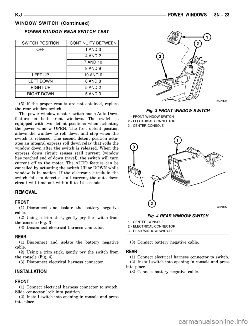
POWER WINDOW REAR SWITCH TEST
SWITCH POSITION CONTINUITY BETWEEN
OFF 1 AND 3
4 AND 2
7 AND 10
8 AND 9
LEFT UP 10 AND 6
LEFT DOWN 6 AND 8
RIGHT UP 5 AND 2
RIGHT DOWN 5 AND 3
(5) If the proper results are not obtained, replace
the rear window switch.
The power window master switch has a Auto-Down
feature on both front windows. The switch is
equipped with two detent positions when actuating
the power window OPEN. The first detent position
allows the window to roll down and stop when the
switch is released. The second detent position actu-
ates an integral express roll down relay that rolls the
window down after the switch is released. When the
express down circuit senses stall current (window
has reached end of down travel), the switch will turn
current off to the motor. The AUTO feature can be
cancelled by actuating the switch UP or DOWN while
window is in motion. If the electronic circuit in the
switch fails to detect a stall current, the auto down
circuit will time out within 9 to 14 seconds.
REMOVAL
FRONT
(1) Disconnect and isolate the battery negative
cable.
(2) Using a trim stick, gently pry the switch from
the console (Fig. 3).
(3) Disconnect electrical harness connector.
REAR
(1) Disconnect and isolate the battery negative
cable.
(2) Using a trim stick, gently pry the switch from
the console (Fig. 4).
(3) Disconnect electrical harness connector.
INSTALLATION
FRONT
(1) Connect electrical harness connector to switch.
Slide connector lock into position.
(2) Install switch into opening in console and press
into place.(3) Connect battery negative cable.
REAR
(1) Connect electrical harness connector to switch.
(2) Install switch into opening in console and press
into place.
(3) Connect battery negative cable.
Fig. 3 FRONT WINDOW SWITCH
1 - FRONT WINDOW SWITCH
2 - ELECTRICAL CONNECTOR
3 - CENTER CONSOLE
Fig. 4 REAR WINDOW SWITCH
1 - CENTER CONSOLE
2 - ELECTRICAL CONNECTOR
3 - REAR WINDOW SWITCH
KJPOWER WINDOWS 8N - 23
WINDOW SWITCH (Continued)
Page 746 of 1803

WIRING
TABLE OF CONTENTS
page page
WIRING DIAGRAM INFORMATION...... 8Wa-01-1
COMPONENT INDEX................. 8Wa-02-1
POWER DISTRIBUTION.............. 8Wa-10-1
JUNCTION BLOCK................... 8Wa-12-1
GROUND DISTRIBUTION............. 8Wa-15-1
BUS COMMUNICATIONS............. 8Wa-18-1
CHARGING SYSTEM................. 8Wa-20-1
STARTING SYSTEM................. 8Wa-21-1
FUEL/IGNITION SYSTEM............. 8Wa-30-1
TRANSMISSION CONTROL SYSTEM.... 8Wa-31-1
VEHICLE SPEED CONTROL........... 8Wa-33-1
ANTILOCK BRAKES.................. 8Wa-35-1
VEHICLE THEFT SECURITY SYSTEM.... 8Wa-39-1
INSTRUMENT CLUSTER.............. 8Wa-40-1
HORN/CIGAR LIGHTER/POWER OUTLET . 8Wa-41-1
AIR CONDITIONING-HEATER.......... 8Wa-42-1
AIRBAG SYSTEM................... 8Wa-43-1
INTERIOR LIGHTING................. 8Wa-44-1BODY CONTROL MODULE............ 8Wa-45-1
AUDIO SYSTEM.................... 8Wa-47-1
REAR WINDOW DEFOGGER........... 8Wa-48-1
OVERHEAD CONSOLE................ 8Wa-49-1
FRONT LIGHTING................... 8Wa-50-1
REAR LIGHTING.................... 8Wa-51-1
TURN SIGNALS..................... 8Wa-52-1
WIPERS........................... 8Wa-53-1
TRAILER TOW...................... 8Wa-54-1
POWER WINDOWS.................. 8Wa-60-1
POWER DOOR LOCKS............... 8Wa-61-1
POWER MIRRORS.................. 8Wa-62-1
POWER SEAT...................... 8Wa-63-1
POWER SUNROOF.................. 8Wa-64-1
SPLICE INFORMATION............... 8Wa-70-1
CONNECTOR PIN-OUTS.............. 8Wa-80-1
CONNECTOR/GROUND/
SPLICE LOCATION................. 8Wa-91-1 KJWIRING
8Wa-1
Page 763 of 1803

Component Page
Low Beam Relay..................... 8Wa-50
Manifold Absolute Pressure Sensor....... 8Wa-30
Multi-Function Switch........... 8Wa-50, 52, 53
Output Speed Sensor.................. 8Wa-31
Overhead Map/Reading Lamp........... 8Wa-44
Oxygen Sensors...................... 8Wa-30
Oxygen Sensor Downstream Relay........ 8Wa-30
Park Brake Switch.................... 8Wa-40
Park Lamp Relay..................... 8Wa-50
Park/Turn Signal Lamps............ 8Wa-50, 52
Passenger Airbag..................... 8Wa-43
Passenger Door Unlock Relay........... 8Wa-61
Passenger Seat Belt Switch............. 8Wa-40
Position Lamps...................... 8Wa-50
Power Distribution Center.............. 8Wa-10
Power Mirrors....................... 8Wa-62
Power Outlet........................ 8Wa-41
Power Seats......................... 8Wa-63
Power Steering Pressure Switch......... 8Wa-30
Power Windows...................... 8Wa-60
Powertrain Control Module............. 8Wa-30
Radiator Fans....................... 8Wa-30
Radio Choke......................... 8Wa-47
Radio.............................. 8Wa-47
Rear Fog Lamp Relay................. 8Wa-51
Rear Power Outlet.................... 8Wa-41
Rear Power Window Switch............. 8Wa-60
Rear Wheel Speed Sensor.............. 8Wa-35
Rear Window Defogger................. 8Wa-48
Rear Wiper Motor.................... 8Wa-53
Red Brake Warning Indicator Switch...... 8Wa-40Component Page
Remote Keyless Entry Module........... 8Wa-45
Remote Radio Switches................ 8Wa-47
Splices............................. 8Wa-10
Sentry Key Immobilizer Module.......... 8Wa-39
Shifter Assembly..................... 8Wa-31
Side Impact Airbag Control Modules...... 8Wa-43
Side Marker Lamps................ 8Wa-50, 52
Side Repeater Lamps............... 8Wa-50, 52
Siren.............................. 8Wa-49
Speed Control Servo................... 8Wa-33
Speed Control Switches................ 8Wa-33
Starter Motor Relay................... 8Wa-21
Starter Motor........................ 8Wa-21
Sunroof............................ 8Wa-64
Tail/Stop Lamps...................... 8Wa-51
Tailgate Cylinder Lock Switch........... 8Wa-61
Tailgate Flip-Up Ajar Switch............ 8Wa-61
Tailgate Lock Motor/Ajar Switch......... 8Wa-61
Throttle Position Sensor................ 8Wa-30
Trailer Tow.......................... 8Wa-54
Transfer Case Position Sensor........ 8Wa-30, 31
Transmission Control Module........... 8Wa-31
Transmission Control Relay............. 8Wa-31
Transmission Solenoid/TRS Assembly..... 8Wa-31
Visor/Vanity Lamps................... 8Wa-44
Washer Fluid Level Switch............. 8Wa-53
Washer Pump........................ 8Wa-53
Water In Fuel Sensor.................. 8Wa-30
Wheel Speed Sensors.................. 8Wa-35
Wiper High/Low Relay................. 8Wa-53
KJ8W-02 COMPONENT INDEX8Wa-02-1
Page 1024 of 1803

8W-60 POWER WINDOWS
Component Page
G301............................. 8Wa-60-2
Ignition Switch..................... 8Wa-60-2
Left Front Power Window Motor........ 8Wa-60-2
Left Rear Power Window Motor........ 8Wa-60-3Component Page
Power Window Master Switch........ 8Wa-60-2, 3
Rear Power Window Switch........... 8Wa-60-3
Right Front Power Window Motor....... 8Wa-60-2
Right Rear Power Window Motor....... 8Wa-60-3
KJ8W-60 POWER WINDOWS8Wa-60-1
Page 1087 of 1803

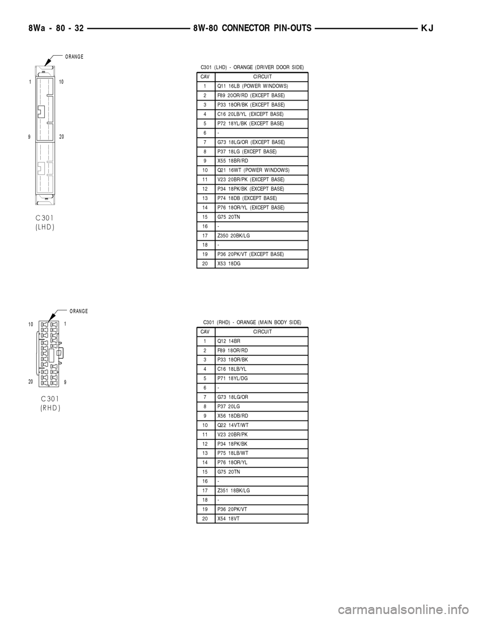
C301 (LHD) - ORANGE (DRIVER DOOR SIDE)
CAV CIRCUIT
1 Q11 16LB (POWER WINDOWS)
2 F89 20OR/RD (EXCEPT BASE)
3 P33 18OR/BK (EXCEPT BASE)
4 C16 20LB/YL (EXCEPT BASE)
5 P72 18YL/BK (EXCEPT BASE)
6-
7 G73 18LG/OR (EXCEPT BASE)
8 P37 18LG (EXCEPT BASE)
9 X55 18BR/RD
10 Q21 16WT (POWER WINDOWS)
11 V23 20BR/PK (EXCEPT BASE)
12 P34 18PK/BK (EXCEPT BASE)
13 P74 18DB (EXCEPT BASE)
14 P76 18OR/YL (EXCEPT BASE)
15 G75 20TN
16 -
17 Z350 20BK/LG
18 -
19 P36 20PK/VT (EXCEPT BASE)
20 X53 18DG
C301 (RHD) - ORANGE (MAIN BODY SIDE)
CAV CIRCUIT
1 Q12 14BR
2 F89 18OR/RD
3 P33 18OR/BK
4 C16 18LB/YL
5 P71 18YL/DG
6-
7 G73 18LG/OR
8 P37 20LG
9 X56 18DB/RD
10 Q22 14VT/WT
11 V23 20BR/PK
12 P34 18PK/BK
13 P75 18LB/WT
14 P76 18OR/YL
15 G75 20TN
16 -
17 Z351 18BK/LG
18 -
19 P36 20PK/VT
20 X54 18VT
8Wa - 80 - 32 8W-80 CONNECTOR PIN-OUTSKJ