evap leak detection JEEP LIBERTY 2002 KJ / 1.G Workshop Manual
[x] Cancel search | Manufacturer: JEEP, Model Year: 2002, Model line: LIBERTY, Model: JEEP LIBERTY 2002 KJ / 1.GPages: 1803, PDF Size: 62.3 MB
Page 313 of 1803
²Fuel injectors
²Ignition coil(s)
²Certain relays/solenoids
²Certain sensors
DESCRIPTION - SENSOR RETURN
The Sensor Return circuits are internal to the Pow-
ertrain Control Module (PCM).
Sensor Return provides a low±noise ground refer-
ence for all engine control system sensors. Refer to
Power Grounds for more information.
OPERATION
OPERATION - PCM
The PCM operates the fuel system. The PCM is a
pre-programmed, triple microprocessor digital com-
puter. It regulates ignition timing, air-fuel ratio,
emission control devices, charging system, certain
transmission features, speed control, air conditioning
compressor clutch engagement and idle speed. The
PCM can adapt its programming to meet changing
operating conditions.
The PCM receives input signals from various
switches and sensors. Based on these inputs, the
PCM regulates various engine and vehicle operations
through different system components. These compo-
nents are referred to as Powertrain Control Module
(PCM) Outputs. The sensors and switches that pro-
vide inputs to the PCM are considered Powertrain
Control Module (PCM) Inputs.
The PCM adjusts ignition timing based upon
inputs it receives from sensors that react to: engine
rpm, manifold absolute pressure, engine coolant tem-
perature, throttle position, transmission gear selec-
tion (automatic transmission), vehicle speed, power
steering pump pressure, and the brake switch.
The PCM adjusts idle speed based on inputs it
receives from sensors that react to: throttle position,
vehicle speed, transmission gear selection, engine
coolant temperature and from inputs it receives from
the air conditioning clutch switch and brake switch.
Based on inputs that it receives, the PCM adjusts
ignition coil dwell. The PCM also adjusts the gener-
ator charge rate through control of the generator
field and provides speed control operation.
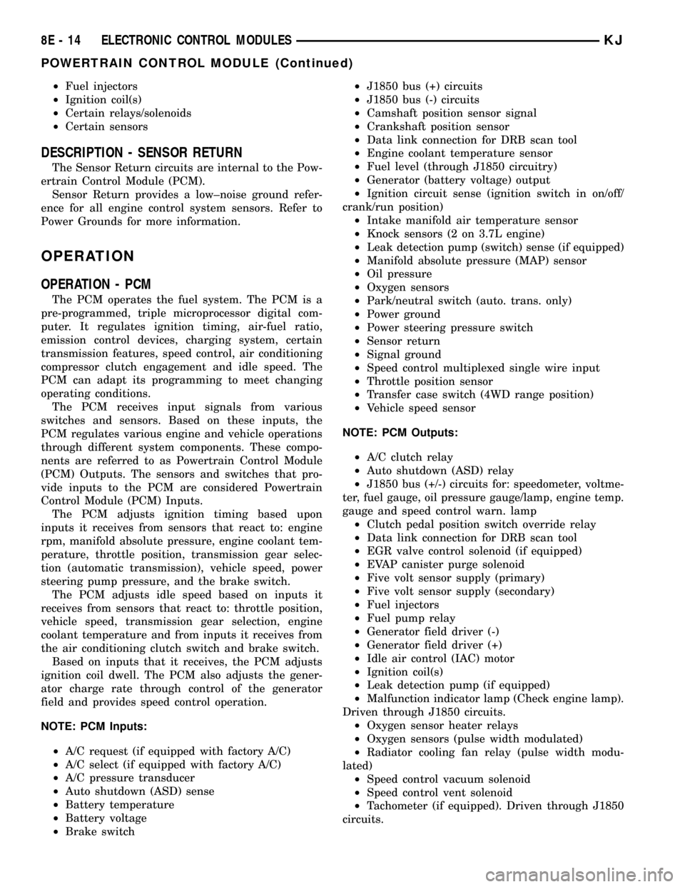
NOTE: PCM Inputs:
²A/C request (if equipped with factory A/C)
²A/C select (if equipped with factory A/C)
²A/C pressure transducer
²Auto shutdown (ASD) sense
²Battery temperature
²Battery voltage
²Brake switch²J1850 bus (+) circuits
²J1850 bus (-) circuits
²Camshaft position sensor signal
²Crankshaft position sensor
²Data link connection for DRB scan tool
²Engine coolant temperature sensor
²Fuel level (through J1850 circuitry)
²Generator (battery voltage) output
²Ignition circuit sense (ignition switch in on/off/
crank/run position)
²Intake manifold air temperature sensor
²Knock sensors (2 on 3.7L engine)
²Leak detection pump (switch) sense (if equipped)
²Manifold absolute pressure (MAP) sensor
²Oil pressure
²Oxygen sensors
²Park/neutral switch (auto. trans. only)
²Power ground
²Power steering pressure switch
²Sensor return
²Signal ground
²Speed control multiplexed single wire input
²Throttle position sensor
²Transfer case switch (4WD range position)
²Vehicle speed sensor
NOTE: PCM Outputs:
²A/C clutch relay
²Auto shutdown (ASD) relay
²J1850 bus (+/-) circuits for: speedometer, voltme-
ter, fuel gauge, oil pressure gauge/lamp, engine temp.
gauge and speed control warn. lamp
²Clutch pedal position switch override relay
²Data link connection for DRB scan tool
²EGR valve control solenoid (if equipped)
²EVAP canister purge solenoid
²Five volt sensor supply (primary)
²Five volt sensor supply (secondary)
²Fuel injectors
²Fuel pump relay
²Generator field driver (-)
²Generator field driver (+)
²Idle air control (IAC) motor
²Ignition coil(s)
²Leak detection pump (if equipped)
²Malfunction indicator lamp (Check engine lamp).
Driven through J1850 circuits.
²Oxygen sensor heater relays
²Oxygen sensors (pulse width modulated)
²Radiator cooling fan relay (pulse width modu-
lated)
²Speed control vacuum solenoid
²Speed control vent solenoid
²Tachometer (if equipped). Driven through J1850
circuits.
8E - 14 ELECTRONIC CONTROL MODULESKJ
POWERTRAIN CONTROL MODULE (Continued)
Page 762 of 1803
8W-02 COMPONENT INDEX
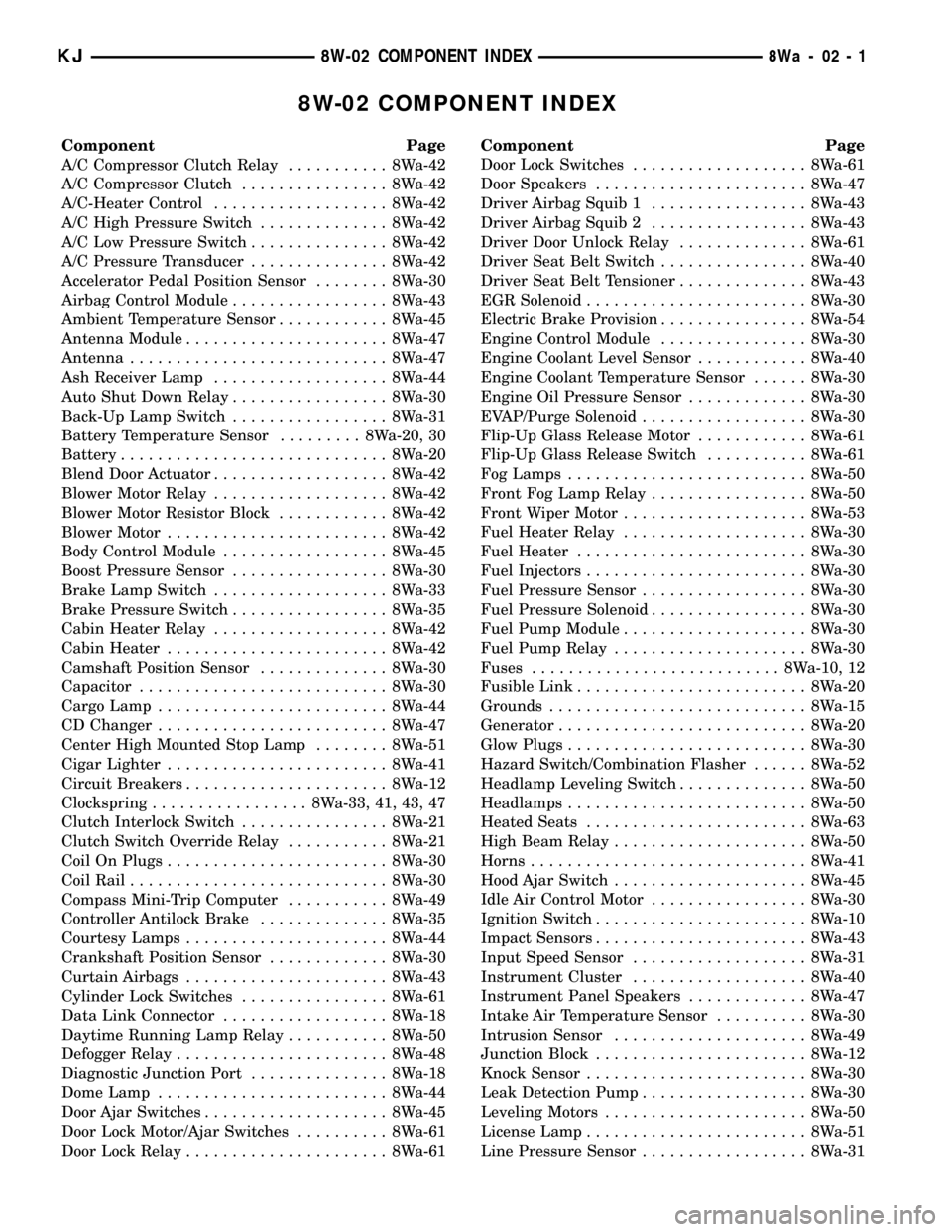
Component Page
A/C Compressor Clutch Relay........... 8Wa-42
A/C Compressor Clutch................ 8Wa-42
A/C-Heater Control................... 8Wa-42
A/C High Pressure Switch.............. 8Wa-42
A/C Low Pressure Switch............... 8Wa-42
A/C Pressure Transducer............... 8Wa-42
Accelerator Pedal Position Sensor........ 8Wa-30
Airbag Control Module................. 8Wa-43
Ambient Temperature Sensor............ 8Wa-45
Antenna Module...................... 8Wa-47
Antenna............................ 8Wa-47
Ash Receiver Lamp................... 8Wa-44
Auto Shut Down Relay................. 8Wa-30
Back-Up Lamp Switch................. 8Wa-31
Battery Temperature Sensor......... 8Wa-20, 30
Battery............................. 8Wa-20
Blend Door Actuator................... 8Wa-42
Blower Motor Relay................... 8Wa-42
Blower Motor Resistor Block............ 8Wa-42
Blower Motor........................ 8Wa-42
Body Control Module.................. 8Wa-45
Boost Pressure Sensor................. 8Wa-30
Brake Lamp Switch................... 8Wa-33
Brake Pressure Switch................. 8Wa-35
Cabin Heater Relay................... 8Wa-42
Cabin Heater........................ 8Wa-42
Camshaft Position Sensor.............. 8Wa-30
Capacitor........................... 8Wa-30
Cargo Lamp......................... 8Wa-44
CD Changer......................... 8Wa-47
Center High Mounted Stop Lamp........ 8Wa-51
Cigar Lighter........................ 8Wa-41
Circuit Breakers...................... 8Wa-12
Clockspring................. 8Wa-33, 41, 43, 47
Clutch Interlock Switch................ 8Wa-21
Clutch Switch Override Relay........... 8Wa-21
Coil On Plugs........................ 8Wa-30
Coil Rail............................ 8Wa-30
Compass Mini-Trip Computer........... 8Wa-49
Controller Antilock Brake.............. 8Wa-35
Courtesy Lamps...................... 8Wa-44
Crankshaft Position Sensor............. 8Wa-30
Curtain Airbags...................... 8Wa-43
Cylinder Lock Switches................ 8Wa-61
Data Link Connector.................. 8Wa-18
Daytime Running Lamp Relay........... 8Wa-50
Defogger Relay....................... 8Wa-48
Diagnostic Junction Port............... 8Wa-18
Dome Lamp......................... 8Wa-44
Door Ajar Switches.................... 8Wa-45
Door Lock Motor/Ajar Switches.......... 8Wa-61
Door Lock Relay...................... 8Wa-61Component Page
Door Lock Switches................... 8Wa-61
Door Speakers....................... 8Wa-47
Driver Airbag Squib 1................. 8Wa-43
Driver Airbag Squib 2................. 8Wa-43
Driver Door Unlock Relay.............. 8Wa-61
Driver Seat Belt Switch................ 8Wa-40
Driver Seat Belt Tensioner.............. 8Wa-43
EGR Solenoid........................ 8Wa-30
Electric Brake Provision................ 8Wa-54
Engine Control Module................ 8Wa-30
Engine Coolant Level Sensor............ 8Wa-40
Engine Coolant Temperature Sensor...... 8Wa-30
Engine Oil Pressure Sensor............. 8Wa-30
EVAP/Purge Solenoid.................. 8Wa-30
Flip-Up Glass Release Motor............ 8Wa-61
Flip-Up Glass Release Switch........... 8Wa-61
Fog Lamps.......................... 8Wa-50
Front Fog Lamp Relay................. 8Wa-50
Front Wiper Motor.................... 8Wa-53
Fuel Heater Relay.................... 8Wa-30
Fuel Heater......................... 8Wa-30
Fuel Injectors........................ 8Wa-30
Fuel Pressure Sensor.................. 8Wa-30
Fuel Pressure Solenoid................. 8Wa-30
Fuel Pump Module.................... 8Wa-30
Fuel Pump Relay..................... 8Wa-30
Fuses........................... 8Wa-10, 12
Fusible Link......................... 8Wa-20
Grounds............................ 8Wa-15
Generator........................... 8Wa-20
Glow Plugs.......................... 8Wa-30
Hazard Switch/Combination Flasher...... 8Wa-52
Headlamp Leveling Switch.............. 8Wa-50
Headlamps.......................... 8Wa-50
Heated Seats........................ 8Wa-63
High Beam Relay..................... 8Wa-50
Horns.............................. 8Wa-41
Hood Ajar Switch..................... 8Wa-45
Idle Air Control Motor................. 8Wa-30
Ignition Switch....................... 8Wa-10
Impact Sensors....................... 8Wa-43
Input Speed Sensor................... 8Wa-31
Instrument Cluster................... 8Wa-40
Instrument Panel Speakers............. 8Wa-47
Intake Air Temperature Sensor.......... 8Wa-30
Intrusion Sensor..................... 8Wa-49
Junction Block....................... 8Wa-12
Knock Sensor........................ 8Wa-30
Leak Detection Pump.................. 8Wa-30
Leveling Motors...................... 8Wa-50
License Lamp........................ 8Wa-51
Line Pressure Sensor.................. 8Wa-31
KJ8W-02 COMPONENT INDEX8Wa-02-1
Page 862 of 1803
8W-30 FUEL/IGNITION SYSTEM
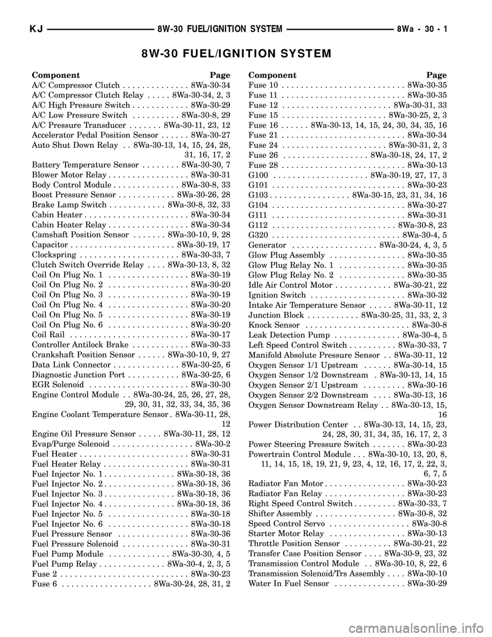
Component Page
A/C Compressor Clutch.............. 8Wa-30-34
A/C Compressor Clutch Relay..... 8Wa-30-34, 2, 3
A/C High Pressure Switch............ 8Wa-30-29
A/C Low Pressure Switch.......... 8Wa-30-8, 29
A/C Pressure Transducer....... 8Wa-30-11, 23, 12
Accelerator Pedal Position Sensor...... 8Wa-30-27
Auto Shut Down Relay . . 8Wa-30-13, 14, 15, 24, 28,
31, 16, 17, 2
Battery Temperature Sensor........ 8Wa-30-30, 7
Blower Motor Relay................. 8Wa-30-31
Body Control Module.............. 8Wa-30-8, 33
Boost Pressure Sensor............ 8Wa-30-26, 28
Brake Lamp Switch............ 8Wa-30-8, 32, 33
Cabin Heater...................... 8Wa-30-34
Cabin Heater Relay................. 8Wa-30-34
Camshaft Position Sensor....... 8Wa-30-10, 9, 28
Capacitor...................... 8Wa-30-19, 17
Clockspring..................... 8Wa-30-33, 7
Clutch Switch Override Relay.... 8Wa-30-13, 8, 32
Coil On Plug No. 1................. 8Wa-30-19
Coil On Plug No. 2................. 8Wa-30-20
Coil On Plug No. 3................. 8Wa-30-19
Coil On Plug No. 4................. 8Wa-30-20
Coil On Plug No. 5................. 8Wa-30-19
Coil On Plug No. 6................. 8Wa-30-20
Coil Rail......................... 8Wa-30-17
Controller Antilock Brake............ 8Wa-30-33
Crankshaft Position Sensor...... 8Wa-30-10, 9, 27
Data Link Connector.............. 8Wa-30-25, 6
Diagnostic Junction Port........... 8Wa-30-25, 6
EGR Solenoid..................... 8Wa-30-30
Engine Control Module . . 8Wa-30-24, 25, 26, 27, 28,
29, 30, 31, 32, 33, 34, 35, 36
Engine Coolant Temperature Sensor . 8Wa-30-11, 28,
12
Engine Oil Pressure Sensor..... 8Wa-30-11, 28, 12
Evap/Purge Solenoid................. 8Wa-30-2
Fuel Heater....................... 8Wa-30-31
Fuel Heater Relay.................. 8Wa-30-31
Fuel Injector No. 1............... 8Wa-30-18, 36
Fuel Injector No. 2............... 8Wa-30-18, 36
Fuel Injector No. 3............... 8Wa-30-18, 36
Fuel Injector No. 4............... 8Wa-30-18, 36
Fuel Injector No. 5................. 8Wa-30-18
Fuel Injector No. 6................. 8Wa-30-18
Fuel Pressure Sensor............... 8Wa-30-36
Fuel Pressure Solenoid.............. 8Wa-30-31
Fuel Pump Module............. 8Wa-30-30, 4, 5
Fuel Pump Relay.............. 8Wa-30-4, 2, 3, 5
Fuse 2........................... 8Wa-30-23
Fuse 6................... 8Wa-30-24, 28, 31, 2Component Page
Fuse 10.......................... 8Wa-30-35
Fuse 11.......................... 8Wa-30-35
Fuse 12....................... 8Wa-30-31, 33
Fuse 15...................... 8Wa-30-25, 2, 3
Fuse 16...... 8Wa-30-13, 14, 15, 24, 30, 34, 35, 16
Fuse 21.......................... 8Wa-30-34
Fuse 24...................... 8Wa-30-31, 2, 3
Fuse 26.................. 8Wa-30-18, 24, 17, 2
Fuse 28.......................... 8Wa-30-13
G100.................... 8Wa-30-19, 27, 17, 3
G101............................ 8Wa-30-23
G103................. 8Wa-30-15, 23, 31, 34, 16
G104............................ 8Wa-30-27
G111 ............................ 8Wa-30-31
G112 .......................... 8Wa-30-8, 23
G320........................... 8Wa-30-4, 5
Generator.................. 8Wa-30-24, 4, 3, 5
Glow Plug Assembly................ 8Wa-30-35
Glow Plug Relay No. 1.............. 8Wa-30-35
Glow Plug Relay No. 2.............. 8Wa-30-35
Idle Air Control Motor............ 8Wa-30-21, 22
Ignition Switch.................... 8Wa-30-32
Intake Air Temperature Sensor..... 8Wa-30-11, 12
Junction Block........... 8Wa-30-25, 31, 33, 2, 3
Knock Sensor...................... 8Wa-30-8
Leak Detection Pump.............. 8Wa-30-4, 5
Left Speed Control Switch.......... 8Wa-30-33, 7
Manifold Absolute Pressure Sensor . . 8Wa-30-11, 12
Oxygen Sensor 1/1 Upstream...... 8Wa-30-14, 15
Oxygen Sensor 1/2 Downstream . 8Wa-30-13, 14, 15
Oxygen Sensor 2/1 Upstream......... 8Wa-30-16
Oxygen Sensor 2/2 Downstream.... 8Wa-30-13, 16
Oxygen Sensor Downstream Relay . . 8Wa-30-13, 15,
16
Power Distribution Center . . 8Wa-30-13, 14, 15, 23,
24, 28, 30, 31, 34, 35, 16, 17, 2, 3
Power Steering Pressure Switch....... 8Wa-30-23
Powertrain Control Module . . . 8Wa-30-10, 13, 20, 8,
11, 14, 15, 18, 19, 21, 9, 23, 4, 12, 16, 17, 2, 22, 3,
6, 7, 5
Radiator Fan Motor................. 8Wa-30-23
Radiator Fan Relay................. 8Wa-30-23
Right Speed Control Switch......... 8Wa-30-33, 7
Shifter Assembly................. 8Wa-30-8, 32
Speed Control Servo................. 8Wa-30-8
Starter Motor Relay................ 8Wa-30-13
Throttle Position Sensor.......... 8Wa-30-21, 22
Transfer Case Position Sensor.... 8Wa-30-9, 23, 32
Transmission Control Module . . 8Wa-30-10, 8, 22, 6
Transmission Solenoid/Trs Assembly.... 8Wa-30-10
Water In Fuel Sensor............... 8Wa-30-29
KJ8W-30 FUEL/IGNITION SYSTEM8Wa-30-1
Page 1057 of 1803
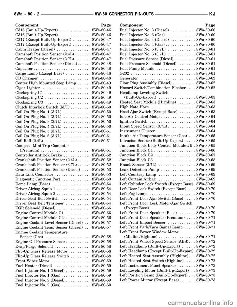
Component Page
C316 (Built-Up-Export).............. 8Wa-80-46
C316 (Built-Up-Export).............. 8Wa-80-46
C317 (Except Built-Up-Export)........ 8Wa-80-47
C317 (Except Built-Up-Export)........ 8Wa-80-47
Cabin Heater (Diesel)............... 8Wa-80-47
Camshaft Position Sensor (2.4L)....... 8Wa-80-47
Camshaft Position Sensor (3.7L)....... 8Wa-80-47
Camshaft Position Sensor (Diesel)...... 8Wa-80-48
Capacitor......................... 8Wa-80-48
Cargo Lamp (Except Base)........... 8Wa-80-48
CD Changer...................... 8Wa-80-48
Center High Mounted Stop Lamp...... 8Wa-80-49
Cigar Lighter..................... 8Wa-80-49
Clockspring C1.................... 8Wa-80-49
Clockspring C2.................... 8Wa-80-49
Clockspring C3.................... 8Wa-80-49
Clutch Interlock Switch (M/T)......... 8Wa-80-50
Coil On Plug No. 1 (3.7L)............ 8Wa-80-50
Coil On Plug No. 2 (3.7L)............ 8Wa-80-50
Coil On Plug No. 3 (3.7L)............ 8Wa-80-50
Coil On Plug No. 4 (3.7L)............ 8Wa-80-50
Coil On Plug No. 5 (3.7L)............ 8Wa-80-51
Coil On Plug No. 6 (3.7L)............ 8Wa-80-51
Coil Rail (2.4L).................... 8Wa-80-51
Compass Mini-Trip Computer
(Premium)...................... 8Wa-80-51
Controller Antilock Brake............ 8Wa-80-52
Crankshaft Position Sensor (2.4L)...... 8Wa-80-52
Crankshaft Position Sensor (3.7L)...... 8Wa-80-52
Crankshaft Position Sensor (Diesel).... 8Wa-80-53
Data Link Connector................ 8Wa-80-53
Diagnostic Junction Port............. 8Wa-80-53
Dome Lamp (Base)................. 8Wa-80-54
Driver Airbag Squib 1............... 8Wa-80-54
Driver Airbag Squib 2............... 8Wa-80-54
Driver Seat Belt Switch............. 8Wa-80-54
Driver Seat Belt Tensioner........... 8Wa-80-54
EGR Solenoid (Diesel)............... 8Wa-80-55
Engine Control Module C1........... 8Wa-80-55
Engine Control Module C2........... 8Wa-80-56
Engine Coolant Level Sensor (Diesel) . . . 8Wa-80-57
Engine Coolant Temp Sensor (Diesel) . . . 8Wa-80-57
Engine Coolant Temperature
Sensor (Gas).................... 8Wa-80-58
Engine Oil Pressure Sensor........... 8Wa-80-58
Evap/Purge Solenoid................ 8Wa-80-58
Flip-Up Glass Release Motor.......... 8Wa-80-58
Flip-Up Glass Release Switch......... 8Wa-80-58
Front Wiper Motor................. 8Wa-80-59
Fuel Heater (Diesel)................ 8Wa-80-59
Fuel Injector No. 1 (Diesel)........... 8Wa-80-59
Fuel Injector No. 1 (Gas)............. 8Wa-80-59
Fuel Injector No. 2 (Diesel)........... 8Wa-80-59
Fuel Injector No. 2 (Gas)............. 8Wa-80-60Component Page
Fuel Injector No. 3 (Diesel)........... 8Wa-80-60
Fuel Injector No. 3 (Gas)............. 8Wa-80-60
Fuel Injector No. 4 (Diesel)........... 8Wa-80-60
Fuel Injector No. 4 (Gas)............. 8Wa-80-60
Fuel Injector No. 5 (3.7L)............ 8Wa-80-61
Fuel Injector No. 6 (3.7L)............ 8Wa-80-61
Fuel Pressure Sensor (Diesel)......... 8Wa-80-61
Fuel Pressure Solenoid (Diesel)........ 8Wa-80-61
Fuel Pump Module................. 8Wa-80-61
G202............................ 8Wa-80-61
Generator........................ 8Wa-80-62
Glow Plug Assembly (Diesel).......... 8Wa-80-62
Hazard Switch/Combination Flasher.... 8Wa-80-62
Headlamp Leveling Switch
(Built-Up-Export)................ 8Wa-80-63
Heated Seat Module (Highline)........ 8Wa-80-63
High Note Horn.................... 8Wa-80-63
Hood Ajar Switch (Except Base)....... 8Wa-80-63
Idle Air Control Motor............... 8Wa-80-64
Ignition Switch.................... 8Wa-80-64
Input Speed Sensor (3.7L)............ 8Wa-80-64
Instrument Cluster................. 8Wa-80-64
Intake Air Temperature Sensor (Gas) . . . 8Wa-80-65
Intrusion Sensor (Built-Up-Export)..... 8Wa-80-65
Junction Block Body Control Module-JB . 8Wa-80-65
Junction Block C1.................. 8Wa-80-66
Junction Block C2.................. 8Wa-80-67
Junction Block C3.................. 8Wa-80-68
Knock Sensor (3.7L)................ 8Wa-80-69
Leak Detection Pump............... 8Wa-80-69
Left Courtesy Lamp................ 8Wa-80-69
Left Curtain Airbag................. 8Wa-80-69
Left Cylinder Lock Switch (Except Base) . 8Wa-80-69
Left Door Lock Switch (Except Base) . . . 8Wa-80-70
Left Fog Lamp..................... 8Wa-80-70
Left Front Door Ajar Switch (Base)..... 8Wa-80-70
Left Front Door Lock Motor/Ajar Switch
(Except Base)................... 8Wa-80-70
Left Front Door Speaker (Base)........ 8Wa-80-70
Left Front Door Speaker (Premium).... 8Wa-80-71
Left Front Impact Sensor............ 8Wa-80-71
Left Front Park/Turn Signal Lamp..... 8Wa-80-71
Left Front Power Window Motor
(Midline/Highline)................ 8Wa-80-71
Left Front Wheel Speed Sensor (ABS) . . . 8Wa-80-72
Left Headlamp (Built-Up-Export)...... 8Wa-80-72
Left Headlamp (Except Built-Up-Export) . 8Wa-80-72
Left Heated Seat Assembly (Highline) . . . 8Wa-80-72
Left Heated Seat Switch (Highline)..... 8Wa-80-72
Left Instrument Panel Speaker........ 8Wa-80-73
Left Leveling Motor (Built-Up-Export) . . 8Wa-80-73
Left Position Lamp (Built-Up-Export) . . . 8Wa-80-73
Left Power Mirror (Except Base)....... 8Wa-80-73
8Wa - 80 - 2 8W-80 CONNECTOR PIN-OUTSKJ
Page 1138 of 1803
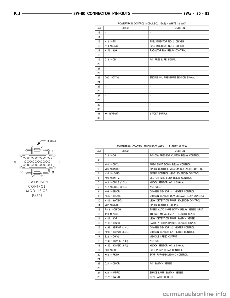
POWERTRAIN CONTROL MODULE-C2 (GAS) - WHITE 32 WAY
CAV CIRCUIT FUNCTION
13 - -
14 - -
15 K12 18TN FUEL INJECTOR NO. 2 DRIVER
16 K14 18LB/BR FUEL INJECTOR NO. 4 DRIVER
17 K173 18LG RADIATOR FAN RELAY CONTROL
18 - -
19 C18 18DB A/C PRESSURE SIGNAL
20 - -
21 - -
22 - -
23 G60 18GY/YL ENGINE OIL PRESSURE SENSOR SIGNAL
24 - -
25 - -
26 - -
27 - -
28 - -
29 - -
30 - -
31 K6 18VT/WT 5 VOLT SUPPLY
32 - -
POWERTRAIN CONTROL MODULE-C3 (GAS) - LT. GRAY 32 WAY
CAV CIRCUIT FUNCTION
1 C13 18DG A/C COMPRESSOR CLUTCH RELAY CONTROL
2- -
3 K51 18DB/YL AUTO SHUT DOWN RELAY CONTROL
4 V36 18TN/RD SPEED CONTROL VACUUM SOLENOID CONTROL
5 V35 18LG/RD SPEED CONTROL VENT SOLENOID CONTROL
6 K90 18TN (M/T) CLUTCH INTERLOCK RELAY CONTROL
7 K42 18DB/LB (3.7L) KNOCK SENSOR NO. 1 SIGNAL
7 K42 18DB/LB (2.4L) NOT USED
8 K99 18BR/OR OXYGEN SENSOR 1/1 HEATER CONTROL
9 K512 18RD/YL OXYGEN SENSOR DOWNSTEAM RELAY CONTROL
10 K106 18WT/DG LEAK DETECTION PUMP SOLENOID CONTROL
11 V32 18YL/RD SPEED CONTROL SUPPLY
12 F142 18OR/DG FUSED AUTO SHUT DOWN RELAY SENSE INPUT
13 T10 18YL/DG TORQUE MANAGEMENT REQUEST SENSE
14 K107 18OR LEAK DETECTION PUMP SWITCH SENSE
15 K118 18PK/YL BATTERY TEMPERATURE SENSOR SIGNAL
16 K299 18BR/WT (2.4L) OXYGEN SENSOR 1/2 HEATER CONTROL
16 K299 18BR/WT (3.7L) OXYGEN SENSOR 2/1 HEATER CONTROL
17 B22 18DG/YL VEHICLE SPEED OUTPUT
18 K142 18GY/BK (2.4L) NOT USED
18 K142 18GY/BK (3.7L) KNOCK SENSOR NO. 2 SIGNAL
19 K31 18BR FUEL PUMP RELAY CONTROL
20 K52 18PK/BK EVAP PURGE/SOLENOID CONTROL
21 - -
22 C21 18DB/OR A/C SWITCH SENSE
23 - -
24 K29 18WT/PK BRAKE LAMP SWITCH SENSE
25 K125 18WT/DB GENERATOR SOURCE
KJ8W-80 CONNECTOR PIN-OUTS8Wa-80-83
Page 1384 of 1803
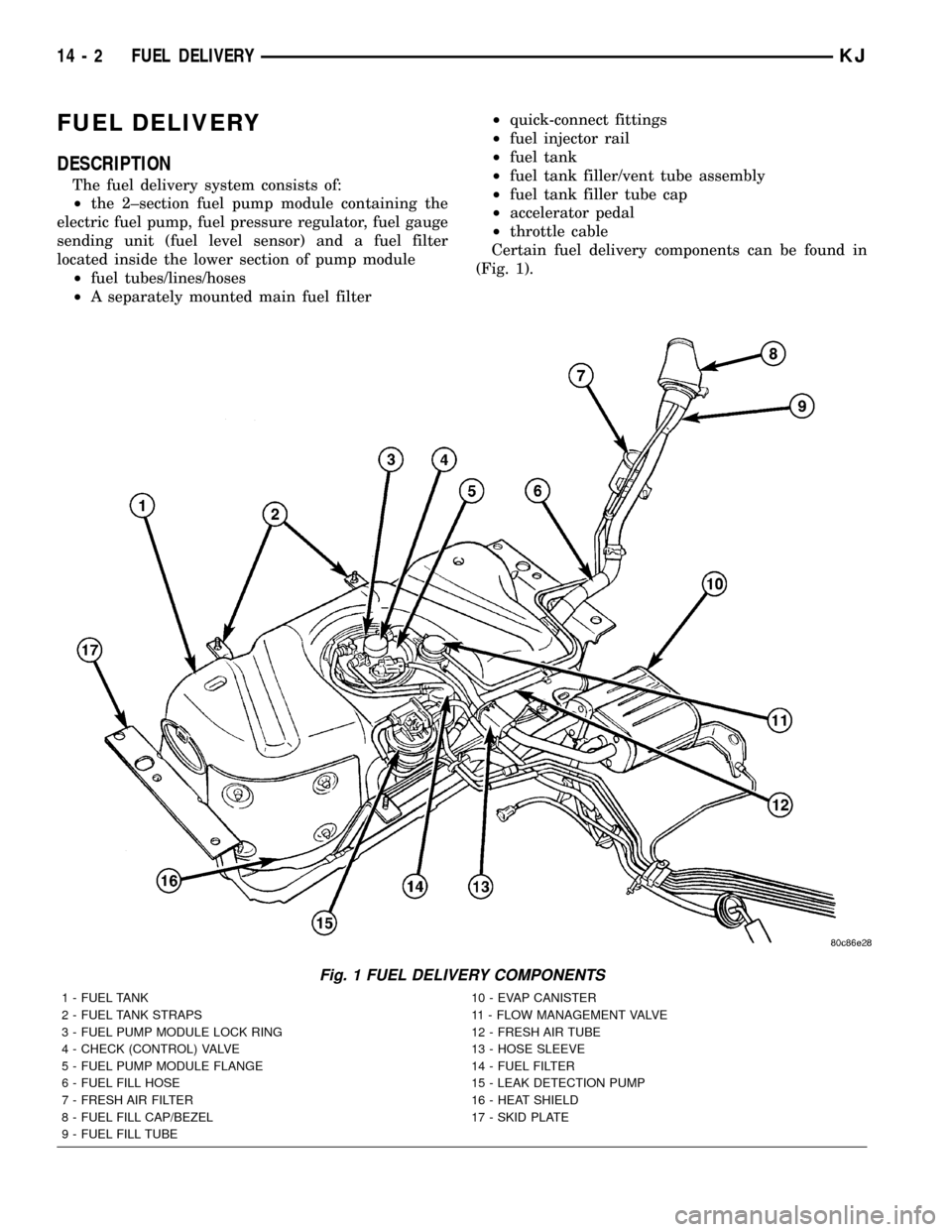
FUEL DELIVERY
DESCRIPTION
The fuel delivery system consists of:
²the 2±section fuel pump module containing the
electric fuel pump, fuel pressure regulator, fuel gauge
sending unit (fuel level sensor) and a fuel filter
located inside the lower section of pump module
²fuel tubes/lines/hoses
²A separately mounted main fuel filter²quick-connect fittings
²fuel injector rail
²fuel tank
²fuel tank filler/vent tube assembly
²fuel tank filler tube cap
²accelerator pedal
²throttle cable
Certain fuel delivery components can be found in
(Fig. 1).
Fig. 1 FUEL DELIVERY COMPONENTS
1 - FUEL TANK 10 - EVAP CANISTER
2 - FUEL TANK STRAPS 11 - FLOW MANAGEMENT VALVE
3 - FUEL PUMP MODULE LOCK RING 12 - FRESH AIR TUBE
4 - CHECK (CONTROL) VALVE 13 - HOSE SLEEVE
5 - FUEL PUMP MODULE FLANGE 14 - FUEL FILTER
6 - FUEL FILL HOSE 15 - LEAK DETECTION PUMP
7 - FRESH AIR FILTER 16 - HEAT SHIELD
8 - FUEL FILL CAP/BEZEL 17 - SKID PLATE
9 - FUEL FILL TUBE
14 - 2 FUEL DELIVERYKJ
Page 1387 of 1803
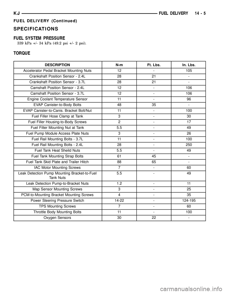
SPECIFICATIONS
FUEL SYSTEM PRESSURE
339 kPa +/- 34 kPa (49.2 psi +/- 2 psi).
TORQUE
DESCRIPTION N-m Ft. Lbs. In. Lbs.
Accelerator Pedal Bracket Mounting Nuts 12 - 105
Crankshaft Position Sensor - 2.4L 28 21 -
Crankshaft Position Sensor - 3.7L 28 21 -
Camshaft Position Sensor - 2.4L 12 - 106
Camshaft Position Sensor - 3.7L 12 - 106
Engine Coolant Temperature Sensor 11 - 96
EVAP Canister-to-Body Bolts 48 35 -
EVAP Canister-to-Canis. Bracket Bolt/Nut 11 - 100
Fuel Filler Hose Clamp at Tank 3 - 30
Fuel Filler Housing-to-Body Screws 2 - 17
Fuel Filter Mounting Nut at Tank 5.5 - 49
Fuel Pump Module Access Plate Nuts 3 - 26
Fuel Rail Mounting Bolts - 3.7L 11 - 100
Fuel Rail Mounting Bolts - 2.4L 28 - 250
Fuel Tank Heat Sheild Nuts 5.5 - 49
Fuel Tank Mounting Strap Bolts 61 45 -
Fuel Tank Skid Plate and Trailer Hitch 88 65 -
IAC Motor Mounting Screws 7 - 60
Leak Detection Pump Mounting Bracket-to-Fuel
Tank Nuts5.5 - 49
Leak Detection Pump-to-Bracket Nuts 1.2 - 11
Map Sensor Mounting Screws 3 - 25
PCM-to-Mounting Bracket Mounting Screws 4 - 35
Power Steering Pressure Switch 14-22 - 124-195
TPS Mounting Screws 7 - 60
Throttle Body Mounting Bolts 11 - 100
Oxygen Sensors 30 22 -
KJFUEL DELIVERY 14 - 5
FUEL DELIVERY (Continued)
Page 1389 of 1803
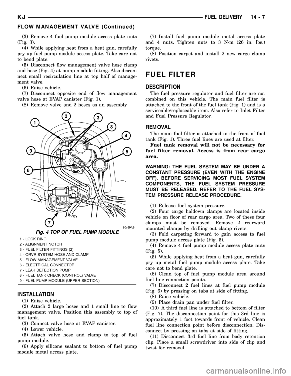
(3) Remove 4 fuel pump module access plate nuts
(Fig. 3).
(4) While applying heat from a heat gun, carefully
pry up fuel pump module access plate. Take care not
to bend plate.
(5) Disconnect flow management valve hose clamp
and hose (Fig. 4) at pump module fitting. Also discon-
nect small recirculation line at top half of manage-
ment valve.
(6) Raise vehicle.
(7) Disconnect opposite end of flow management
valve hose at EVAP canister (Fig. 1).
(8) Remove valve and 2 hoses as an assembly.
INSTALLATION
(1) Raise vehicle.
(2) Attach 2 large hoses and 1 small line to flow
management valve. Position this assembly to top of
fuel tank.
(3) Connect valve hose at EVAP canister.
(4) Lower vehicle.
(5) Attach valve hose and clamp to top of fuel
pump module.
(6) Apply silicone sealant to bottom of fuel pump
module metal access plate.(7) Install fuel pump module metal access plate
and 4 nuts. Tighten nuts to 3 N´m (26 in. lbs.)
torque.
(8) Position carpet and install 2 new cargo clamp
rivets.
FUEL FILTER
DESCRIPTION
The fuel pressure regulator and fuel filter are not
combined on this vehicle. The main fuel filter is
attached to the front of the fuel tank (Fig. 1) and is a
serviceable/replaceable item. Also refer to Inlet Filter
and Fuel Pressure Regulator.
REMOVAL
The main fuel filter is attached to the front of fuel
tank (Fig. 1). Three fuel lines are used at filter.
Fuel tank removal will not be necessary for
fuel filter removal. Access is from rear cargo
area.
WARNING: THE FUEL SYSTEM MAY BE UNDER A
CONSTANT PRESSURE (EVEN WITH THE ENGINE
OFF). BEFORE SERVICING MOST FUEL SYSTEM
COMPONENTS, THE FUEL SYSTEM PRESSURE
MUST BE RELEASED. REFER TO THE FUEL SYS-
TEM PRESSURE RELEASE PROCEDURE.
(1) Release fuel system pressure.
(2) Four cargo holdown clamps are located inside
vehicle on floor of rear cargo area. Two of these four
clamps must be removed. Remove 2 rearward
mounted clamps by drilling out clamp rivets.
(3) Fold carpeting forward to gain access to fuel
pump module access plate (Fig. 5).
(4) Remove 4 fuel pump module access plate nuts
(Fig. 5).
(5) While applying heat from a heat gun, carefully
pry up metal fuel pump module access plate. Take
care not to bend plate.
(6) Clean top of fuel pump module area around
fuel line connection points.
(7) Disconnect 2 fuel lines at fuel pump module
(Fig. 6) by pressing on tabs at side of fitting.
(8) Raise vehicle.
(9) Place drain pan under fuel filter.
(10) A third fuel line is attached to bottom of filter
(Fig. 7). The disconnection point for this 3rd line is
approximately 1 foot towards front of vehicle. Clean
fuel line connection point before disconnection. Dis-
connect by pressing on tabs at side of fitting.
(11) Disconnect 3rd fuel line from body retention
clip. Place a small screwdriver into side of clip and
twist for removal.
Fig. 4 TOP OF FUEL PUMP MODULE
1 - LOCK RING
2 - ALIGNMENT NOTCH
3 - FUEL FILTER FITTINGS (2)
4 - ORVR SYSTEM HOSE AND CLAMP
5 - FLOW MANAGEMENT VALVE
6 - ELECTRICAL CONNECTOR
7 - LEAK DETECTION PUMP
8 - FUEL TANK CHECK (CONTROL) VALVE
9 - FUEL PUMP MODULE (UPPER SECTION)
KJFUEL DELIVERY 14 - 7
FLOW MANAGEMENT VALVE (Continued)
Page 1391 of 1803
FUEL LEVEL SENDING UNIT /
SENSOR
DESCRIPTION
The fuel gauge sending unit (fuel level sensor) is
attached to the side of the fuel pump module. The
sending unit consists of a float, an arm, and a vari-
able resistor track (card).
OPERATION
The fuel pump module has 4 different circuits
(wires). Two of these circuits are used for the fuel
gauge sending unit for fuel gauge operation, and for
certain OBD II emission requirements. The other 2
wires are used for electric fuel pump operation.
For Fuel Gauge Operation:A constant current
source of approximately 32 milliamps is supplied to
the resistor track on the fuel gauge sending unit.
This is fed directly from the Powertrain Control Mod-
ule (PCM).NOTE: For diagnostic purposes, this
12V power source can only be verified with the
circuit opened (fuel pump module electrical
connector unplugged). With the connectors
plugged, output voltages will vary from about
0.6 volts at FULL, to about 8.6 volts at EMPTY
(about 8.6 volts at EMPTY for Jeep models, and
about 7.0 volts at EMPTY for Dodge Truck mod-
els).The resistor track is used to vary the voltage
(resistance) depending on fuel tank float level. As
fuel level increases, the float and arm move up,
which decreases voltage. As fuel level decreases, the
float and arm move down, which increases voltage.
The varied voltage signal is returned back to the
PCM through the sensor return circuit.
Both of the electrical circuits between the fuel
gauge sending unit and the PCM are hard-wired (not
multi-plexed). After the voltage signal is sent from
the resistor track, and back to the PCM, the PCM
will interpret the resistance (voltage) data and send
a message across the multi-plex bus circuits to the
instrument panel cluster. Here it is translated into
the appropriate fuel gauge level reading. Refer to
Instrument Panel for additional information.
For OBD II Emission Monitor Requirements:
The PCM will monitor the voltage output sent from
the resistor track on the sending unit to indicate fuel
level. The purpose of this feature is to prevent the
OBD II system from recording/setting false misfire
and fuel system monitor diagnostic trouble codes.
The feature is activated if the fuel level in the tank
is less than approximately 15 percent of its rated
capacity. If equipped with a Leak Detection Pump
(EVAP system monitor), this feature will also be acti-
vated if the fuel level in the tank is more than
approximately 85 percent of its rated capacity.
DIAGNOSIS AND TESTING - FUEL LEVEL
SENDING UNIT
The fuel level sending unit contains a variable
resistor (track). As the float moves up or down, elec-
trical resistance will change. Refer to Instrument
Panel and Gauges for Fuel Gauge testing. To test the
gauge sending unit only, it must be removed from
vehicle. The unit is a separate part of the lower fuel
pump module section. Refer to Fuel Pump Module
Removal/Installation for procedures (remove only the
upper section of the fuel pump module). Measure the
resistance across the sending unit terminals. With
float in up position, resistance should be 20 ohms (+/-
5%). With float in down position, resistance should be
270 ohms (+/- 5%).
REMOVAL
The fuel level sending unit (fuel level sensor) and
float assembly is located on the side of the lower sec-
tion of the fuel pump module. The lower section of
the fuel pump module is located within the fuel tank.
(1) Remove lower section of fuel pump module
from fuel tank. Refer to Fuel Pump Module Removal/
Installation.
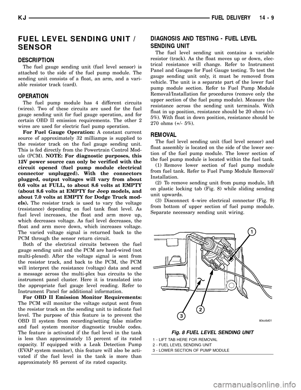
(2) To remove sending unit from pump module, lift
on plastic locking tab (Fig. 8) while sliding sending
unit upwards.
(3) Disconnect 4±wire electrical connector (Fig. 9)
from bottom of upper section of fuel pump module.
Separate necessary sending unit wiring.
Fig. 8 FUEL LEVEL SENDING UNIT
1 - LIFT TAB HERE FOR REMOVAL
2 - FUEL LEVEL SENDING UNIT
3 - LOWER SECTION OF PUMP MODULE
KJFUEL DELIVERY 14 - 9
Page 1406 of 1803
(14) If fuel injectors are to be removed, refer to
Fuel Injector Removal/Installation.
INSTALLATION
2.4L Engine
(1) If fuel injectors are to be installed, refer to Fuel
Injector Removal/Installation.
(2) Clean out fuel injector machined bores in
intake manifold.
(3) Apply a small amount of engine oil to each fuel
injector o-ring. This will help in fuel rail installation.
(4) Position fuel rail/fuel injector assembly to
machined injector openings in intake manifold.
(5) Guide each injector into cylinder head. Be care-
ful not to tear injector o-rings.
(6) Push fuel rail down until fuel injectors have
bottomed on shoulders.
(7) Install 2 fuel rail mounting bolts and tighten.
Refer to torque specifications.
(8) Connect electrical connectors at all fuel injec-
tors. To install connector, refer to (Fig. 37). Push con-
nector onto injector (1) and then push and lock red
colored slider (2). Verify connector is locked to injec-
tor by lightly tugging on connector.
(9) Snap 2 injection wiring harness clips (Fig. 35)
into brackets.
(10) Connect 2 main engine harness connectors at
rear of intake manifold (Fig. 34).
(11) Tighten 5 intake manifold mounting bolts.
Refer to Engine Torque Specifications.
(12) Install PCV valve and hose.
(13) Install thermostat and radiator hose. Fill with
coolant. Refer to Cooling.
(14) Connect necessary vacuum lines to throttle
body.
(15) Connect fuel line latch clip and fuel line to
fuel rail. Refer to Quick-Connect Fittings.
(16) Install air duct to throttle body.
(17) Connect battery cable to battery.
(18) Start engine and check for leaks.
3.7L Engine
(1) If fuel injectors are to be installed, refer to Fuel
Injector Removal/Installation.
(2) Clean out fuel injector machined bores in
intake manifold.
(3) Apply a small amount of engine oil to each fuel
injector o-ring. This will help in fuel rail installation.
(4) Position fuel rail/fuel injector assembly to
machined injector openings in cylinder head.
(5) Guide each injector into cylinder head. Be care-
ful not to tear injector o-rings.
(6) Pushrightside of fuel rail down until fuel
injectors have bottomed on cylinder head shoulder.Pushleftfuel rail down until injectors have bot-
tomed on cylinder head shoulder.
(7) Install 4 fuel rail mounting bolts and tighten.
Refer to torque specifications.
(8) Install 6 ignition coils. Refer to Ignition Coil
Removal/Installation.
(9) Connect electrical connectors to throttle body.
(10) Connect electrical connectors at all fuel injec-
tors. To install connector, refer to (Fig. 37). Push con-
nector onto injector (1) and then push and lock red
colored slider (2). Verify connector is locked to injec-
tor by lightly tugging on connector.
(11) Connect necessary vacuum lines to throttle
body.
(12) Connect fuel line latch clip and fuel line to
fuel rail. Refer to Quick-Connect Fittings.
(13) Install air box to throttle body.
(14) Install air duct to air box.
(15) Connect battery cable to battery.
(16) Start engine and check for leaks.
FUEL TANK
DESCRIPTION
The fuel tank is constructed of a plastic material.
Its main functions are for fuel storage and for place-
ment of the fuel pump module, and certain ORVR
components.
OPERATION
All models pass a full 360 degree rollover test
without fuel leakage. To accomplish this, fuel and
vapor flow controls are required for all fuel tank con-
nections.
A check (control) valve is mounted into the top sec-
tion of the 2±piece fuel pump module. Refer to Fuel
Tank Check Valve for additional information.
An evaporation control system is connected to the
fuel tank to reduce emissions of fuel vapors into the
atmosphere. When fuel evaporates from the fuel
tank, vapors pass through vent hoses or tubes to a
charcoal canister where they are temporarily held.
When the engine is running, the vapors are drawn
into the intake manifold. Certain models are also
equipped with a self-diagnosing system using a Leak
Detection Pump (LDP) and/or an ORVR system.
Refer to Emission Control System for additional
information.
14 - 24 FUEL DELIVERYKJ
FUEL RAIL (Continued)