gas JEEP LIBERTY 2002 KJ / 1.G Workshop Manual
[x] Cancel search | Manufacturer: JEEP, Model Year: 2002, Model line: LIBERTY, Model: JEEP LIBERTY 2002 KJ / 1.GPages: 1803, PDF Size: 62.3 MB
Page 1 of 1803
JEEP
ž
2002
LIBERTY
SERVICE MANUAL and
2.4L GAS SUPPLEMENT
To order the special service tools used and
illustrated, please refer to the instructions on
inside back cover.
NO PART OF THIS PUBLICATION MAY BE
REPRODUCED, STORED IN A RETRIEVAL
SYSTEM, OR TRANSMITTED, IN ANY FORM OR
BY ANY MEANS, ELECTRONIC, MECHANICAL,
PHOTOCOPYING, RECORDING, OR OTHERWISE,
WITHOUT THE PRIOR WRITTEN PERMISSION
OF DAIMLERCHRYSLER CORPORATION.
DaimlerChrysler Corporation reserves the right to make changes in design or
to make additions to or improvements in its products without imposing any
obligations upon itself to install them on its products previously manufac-
tured.
Litho in U.S.A. Copyright 2001 DaimlerChrysler Corporation
7.5M0901
Page 2 of 1803

FOREWORD
This manual is designed as a supplement to be used along with the 2002 Liberty service manual,
81-370-02060. It includes information related to the 2.4L gas engine installed in this vehicle by
DaimlerChrysler Corporation. For diagnosis or service procedures relating to other components or systems,
refer to the 2002 Liberty Service Manual.
The information contained in this service manual has been prepared for the professional automotive tech-
nician involved in daily repair operations. Information describing the operation and use of standard and
optional equipment is included in the Owner's Manual provided with the vehicle.
Information in this manual is divided into groups. These groups contain description, operation, diagnosis,
testing, adjustments, removal, installation, disassembly, and assembly procedures for the systems and compo-
nents. To assist in locating a group title page, use the Group Tab Locator on the following page. The solid bar
after the group title is aligned to a solid tab on the first page of each group. The first page of the group has
a contents section that lists major topics within the group. If you are not sure which Group contains the infor-
mation you need, look up the Component/System in the alphabetical index located in the rear of this manual.
A Service Manual Comment form is included at the rear of this manual. Use the form to provide
DaimlerChrysler Corporation with your comments and suggestions.
Tightening torques are provided as a specific value throughout this manual. This value represents the
midpoint of the acceptable engineering torque range for a given fastener application. These torque values are
intended for use in service assembly and installation procedures using the correct OEM fasteners. When
replacing fasteners, always use the same type (part number) fastener as removed.
DaimlerChrysler Corporation reserves the right to change testing procedures, specifications, diagnosis,
repair methods, or vehicle wiring at any time without prior notice or incurring obligation.
Page 3 of 1803
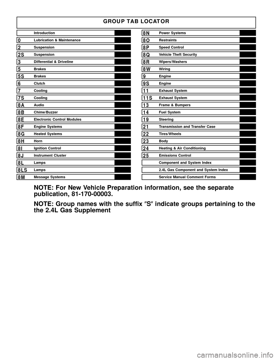
GROUP TAB LOCATOR
Introduction
0Lubrication & Maintenance
2Suspension
2SSuspension
3Differential & Driveline
5Brakes
5SBrakes
6Clutch
7Cooling
7SCooling
8AAudio
8BChime/Buzzer
8EElectronic Control Modules
8FEngine Systems
8GHeated Systems
8HHorn
8IIgnition Control
8JInstrument Cluster
8LLamps
8LSLamps
8MMessage Systems
8NPower Systems
8ORestraints
8PSpeed Control
8QVehicle Theft Security
8RWipers/Washers
8WWiring
9Engine
9SEngine
11Exhaust System
11SExhaust System
13Frame & Bumpers
14Fuel System
19Steering
21Transmission and Transfer Case
22Tires/Wheels
23Body
24Heating & Air Conditioning
25Emissions Control
Component and System Index
2.4L Gas Component and System Index
Service Manual Comment Forms
NOTE: For New Vehicle Preparation information, see the separate
publication, 81-170-00003.
NOTE: Group names with the suffix(S(indicate groups pertaining to the
the 2.4L Gas Supplement
Page 12 of 1803
VEHICLE IDENTIFICATION NUMBER DECODING CHART
POSITION INTERPRETATION CODE = DESCRIPTION
1 Country of Origin 1 = United States
2 Make J = Jeep
3 Vehicle Type 4 = MPV W/O Side Airbags.
8 = MPV With Side Airbags.
4 Gross Vehicle Weight Rating F = 4001 - 5000 lbs.
G = 5001 - 6000 lbs.
5 Vehicle Line K = Liberty 4X2 (LHD)
L = Liberty 4X4 (LHD)
M = Cherokee 4X4 (RHD)
6 Series 3 = Liberty Renegade
4 = Liberty Sport/Cherokee Sport
5 = Liberty Limited/Cherokee Limited
7 Body Style 8 = Sport Utility - 4 Door
8 Engine K = 3.7L 6 cyl MPI Gasoline
1 = 2.4L 4 cyl MPI Gasoline
7 = 2.5L 4 cyl Diesel
9 Check Digit 0 through 9 or X
10 Model Year 2=2002
11 Assembly Plant W = Toledo North Assembly Plant
12 thru 17 Vehicle Build Sequence
VEHICLE SAFETY
CERTIFICATION LABEL
DESCRIPTION
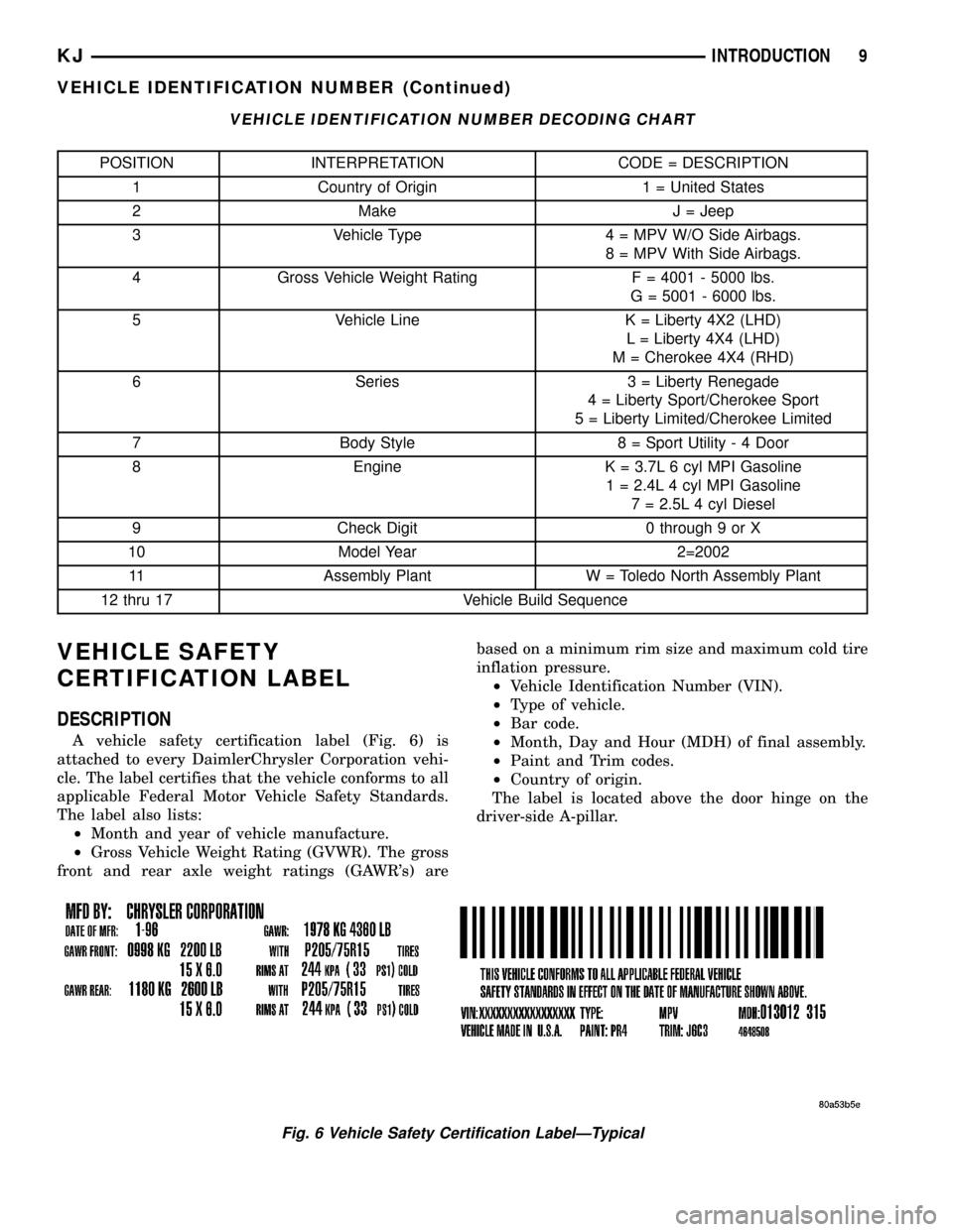
A vehicle safety certification label (Fig. 6) is
attached to every DaimlerChrysler Corporation vehi-
cle. The label certifies that the vehicle conforms to all
applicable Federal Motor Vehicle Safety Standards.
The label also lists:
²Month and year of vehicle manufacture.
²Gross Vehicle Weight Rating (GVWR). The gross
front and rear axle weight ratings (GAWR's) arebased on a minimum rim size and maximum cold tire
inflation pressure.
²Vehicle Identification Number (VIN).
²Type of vehicle.
²Bar code.
²Month, Day and Hour (MDH) of final assembly.
²Paint and Trim codes.
²Country of origin.
The label is located above the door hinge on the
driver-side A-pillar.
Fig. 6 Vehicle Safety Certification LabelÐTypical
KJINTRODUCTION 9
VEHICLE IDENTIFICATION NUMBER (Continued)
Page 59 of 1803
HALF SHAFT
TABLE OF CONTENTS
page page
HALF SHAFT
CAUTION.............................10
DIAGNOSIS AND TESTING - HALF SHAFT....10
REMOVAL.............................10
INSTALLATION.........................11
SPECIFICATIONS
HALF SHAFT.........................11SPECIAL TOOLS.......................12
CV JOINT/BOOT-OUTER
REMOVAL.............................12
INSTALLATION.........................13
CV JOINT/BOOT-INNER
REMOVAL.............................15
INSTALLATION.........................17
HALF SHAFT
CAUTION
CAUTION:: Never grasp half shaft assembly by the
boots. This may cause the boot to pucker or crease
and reduce the service life of the boot.
Avoid over angulating or stroking the C/V joints
when handling the half shaft.
Half shafts exposed to battery acid, transmission
fluid, brake fluid, differential fluid or gasoline may
cause the boots to deteriorate.
DIAGNOSIS AND TESTING - HALF SHAFT
Check for grease at the inboard and outboard C/V
joint. This is a sign of boot or boot clamp damage.
NOISE AND/OR VIBRATION IN TURNS
A clicking noise or a vibration in turns could be
caused by a damaged outer C/V or inner tripod joint
seal boot or seal boot clamps. This will result in the
loss/contamination of the joint grease, resulting in
inadequate lubrication of the joint. Noise could also
be caused by another component of the vehicle com-
ing in contact with the half shafts.
CLUNKING NOISE DURING ACCELERATION
This noise may be a result of a damaged or worn
C/V joint. A torn boot or loose/missing clamp on the
inner/outer joint which has allowed the grease to be
lost will damage the C/V joint.
SHUDDER OR VIBRATION DURING ACCELERATION
This problem could be a result of a worn/damaged
inner tripod joint or a sticking tripod joint. Improper
wheel alignment may also cause a shudder or vibration.
VIBRATION AT HIGHWAY SPEEDS
This problem could be a result of out of balance
front tires or tire/wheel runout. Foreign material
(mud, etc.) packed on the backside of the wheel(s)
will also cause a vibration.
REMOVAL
(1) Raise and support vehicle.
(2) Remove wheel and tire assembly.
(3) Remove half shaft hub nut.
(4) Remove stabilizer link (Fig. 1).
Fig. 1 STABILIZER BAR LINK
1 - STABILIZER BAR
2 - STABILIZER BAR LINK
3 - 10 HALF SHAFTKJ
Page 120 of 1803
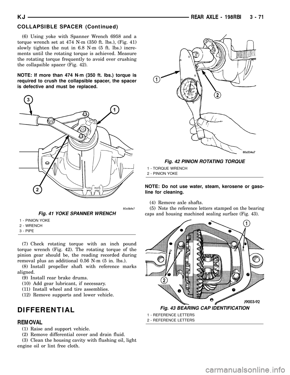
(6) Using yoke with Spanner Wrench 6958 and a
torque wrench set at 474 N´m (350 ft. lbs.), (Fig. 41)
slowly tighten the nut in 6.8 N´m (5 ft. lbs.) incre-
ments until the rotating torque is achieved. Measure
the rotating torque frequently to avoid over crushing
the collapsible spacer (Fig. 42).
NOTE: If more than 474 N´m (350 ft. lbs.) torque is
required to crush the collapsible spacer, the spacer
is defective and must be replaced.
(7) Check rotating torque with an inch pound
torque wrench (Fig. 42). The rotating torque of the
pinion gear should be, the reading recorded during
removal plus an additional 0.56 N´m (5 in. lbs.).
(8) Install propeller shaft with reference marks
aligned.
(9) Install rear brake drums.
(10) Add gear lubricant, if necessary.
(11) Install wheel and tire assemblies.
(12) Remove supports and lower vehicle.
DIFFERENTIAL
REMOVAL
(1) Raise and support vehicle.
(2) Remove differential cover and drain fluid.
(3) Clean the housing cavity with flushing oil, light
engine oil or lint free cloth.NOTE: Do not use water, steam, kerosene or gaso-
line for cleaning.
(4) Remove axle shafts.
(5)
Note the reference letters stamped on the bearing
caps and housing machined sealing surface (Fig. 43).
Fig. 41 YOKE SPANNER WRENCH
1 - PINION YOKE
2 - WRENCH
3 - PIPE
Fig. 42 PINION ROTATING TORQUE
1 - TORQUE WRENCH
2 - PINION YOKE
Fig. 43 BEARING CAP IDENTIFICATION
1 - REFERENCE LETTERS
2 - REFERENCE LETTERS
KJREAR AXLE - 198RBI 3 - 71
COLLAPSIBLE SPACER (Continued)
Page 153 of 1803
lbs.) increments until proper rotating torque is
achieved.
NOTE: The bearing rotating torque should be con-
stant during a complete revolution of the pinion. If
the rotating torque varies, it indicates a binding
condition.
(9) The seal replacement is unacceptable if the
final pinion nut torque is less than 285 N´m (210 ft.
lbs.).
(10) Install the propeller shaft with the installa-
tion reference marks aligned.
(11) Install the brake drums.
(12) Check the differential housing lubricant level.
(13) Install wheel and tire assemblies and lower
the vehicle.
DIFFERENTIAL
REMOVAL
(1) Raise and support vehicle.
(2) Remove fill hole plug from the differential
housing cover.
(3) Remove differential housing cover and drain
housing.
(4) Clean the housing cavity with a flushing oil,
light engine oil or lint free cloth.Do not use water,
steam, kerosene or gasoline for cleaning.(5) Remove the axle shafts.
NOTE: Side play resulting from bearing races being
loose on case hubs requires replacement of the dif-
ferential case.
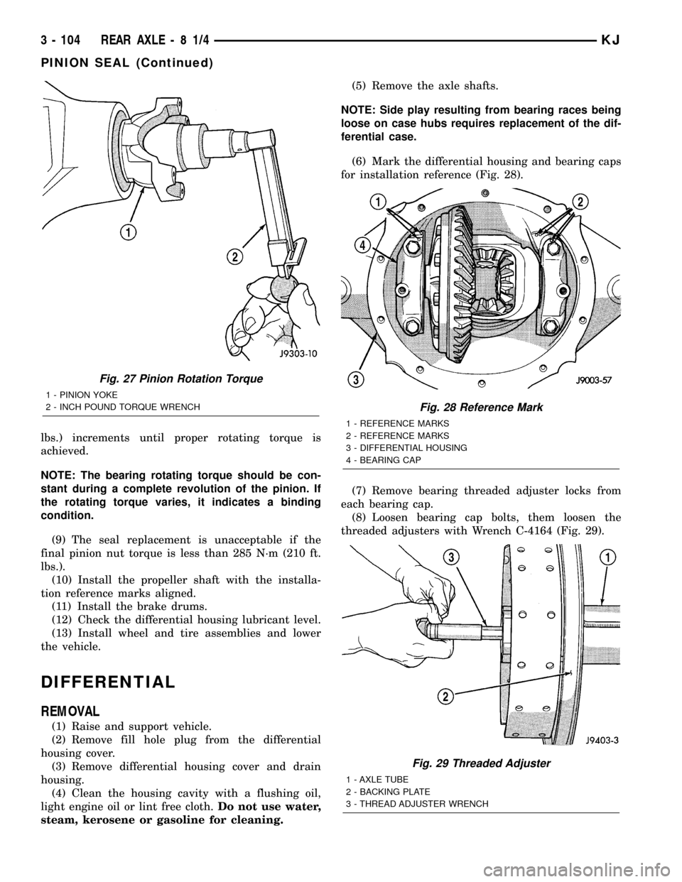
(6) Mark the differential housing and bearing caps
for installation reference (Fig. 28).
(7) Remove bearing threaded adjuster locks from
each bearing cap.
(8) Loosen bearing cap bolts, them loosen the
threaded adjusters with Wrench C-4164 (Fig. 29).
Fig. 27 Pinion Rotation Torque
1 - PINION YOKE
2 - INCH POUND TORQUE WRENCH
Fig. 28 Reference Mark
1 - REFERENCE MARKS
2 - REFERENCE MARKS
3 - DIFFERENTIAL HOUSING
4 - BEARING CAP
Fig. 29 Threaded Adjuster
1 - AXLE TUBE
2 - BACKING PLATE
3 - THREAD ADJUSTER WRENCH
3 - 104 REAR AXLE-81/4KJ
PINION SEAL (Continued)
Page 167 of 1803
CAUTION: Never use gasoline, kerosene, alcohol,
motor oil, transmission fluid, or any fluid containing
mineral oil to clean the system components. These
fluids damage rubber cups and seals. Use only
fresh brake fluid or Mopar brake cleaner to clean or
flush brake system components. These are the only
cleaning materials recommended. If system contam-
ination is suspected, check the fluid for dirt, discol-
oration, or separation into distinct layers. Also
check the reservoir cap seal for distortion. Drain
and flush the system with new brake fluid if con-
tamination is suspected.
CAUTION: Use Mopar brake fluid, or an equivalent
quality fluid meeting SAE/DOT standards J1703 and
DOT 3. Brake fluid must be clean and free of con-
taminants. Use fresh fluid from sealed containers
only to ensure proper antilock component opera-
tion.
CAUTION: Use Mopar multi-mileage or high temper-
ature grease to lubricate caliper slide surfaces,
drum brake pivot pins, and shoe contact points on
the backing plates. Use multi-mileage grease or GE
661 or Dow 111 silicone grease on caliper slide pins
to ensure proper operation.
DIAGNOSIS AND TESTING - BASE BRAKE
SYSTEM
Base brake components consist of the brake shoes,
calipers, wheel cylinders, brake drums, rotors, brake
lines, master cylinder, booster, and parking brake
components.
Brake diagnosis involves determining if the prob-
lem is related to a mechanical, hydraulic, or vacuum
operated component.
The first diagnosis step is the preliminary check.
PRELIMINARY BRAKE CHECK
(1) Check condition of tires and wheels. Damaged
wheels and worn, damaged, or underinflated tires
can cause pull, shudder, vibration, and a condition
similar to grab.
(2) If complaint was based on noise when braking,
check suspension components. Jounce front and rear
of vehicle and listen for noise that might be caused
by loose, worn or damaged suspension or steering
components.
(3) Inspect brake fluid level and condition. Note
that the brake reservoir fluid level will decrease in
proportion to normal lining wear.Also note that
brake fluid tends to darken over time. This is
normal and should not be mistaken for contam-
ination.(a) If fluid level is abnormally low, look for evi-
dence of leaks at calipers, wheel cylinders, brake
lines, and master cylinder.
(b) If fluid appears contaminated, drain out a
sample to examine. System will have to be flushed
if fluid is separated into layers, or contains a sub-
stance other than brake fluid. The system seals
and cups will also have to be replaced after flush-
ing. Use clean brake fluid to flush the system.
(4) Check parking brake operation. Verify free
movement and full release of cables and pedal. Also
note if vehicle was being operated with parking
brake partially applied.
(5) Check brake pedal operation. Verify that pedal
does not bind and has adequate free play. If pedal
lacks free play, check pedal and power booster for
being loose or for bind condition. Do not road test
until condition is corrected.
(6) Check booster vacuum check valve and hose.
(7) If components checked appear OK, road test
the vehicle.
ROAD TESTING
(1) If complaint involved low brake pedal, pump
pedal and note if it comes back up to normal height.
(2) Check brake pedal response with transmission
in Neutral and engine running. Pedal should remain
firm under constant foot pressure.
(3) During road test, make normal and firm brake
stops in 25-40 mph range. Note faulty brake opera-
tion such as low pedal, hard pedal, fade, pedal pulsa-
tion, pull, grab, drag, noise, etc.
(4) Attempt to stop the vehicle with the parking
brake only and note grab, drag, noise, etc.
PEDAL FALLS AWAY
A brake pedal that falls away under steady foot
pressure is generally the result of a system leak. The
leak point could be at a brake line, fitting, hose, or
caliper/wheel cylinder. If leakage is severe, fluid will
be evident at or around the leaking component.
Internal leakage (seal by-pass) in the master cylin-
der caused by worn or damaged piston cups, may
also be the problem cause.
An internal leak in the ABS or RWAL system may
also be the problem with no physical evidence.
LOW PEDAL
If a low pedal is experienced, pump the pedal sev-
eral times. If the pedal comes back up worn linings,
rotors, drums, or rear brakes out of adjustment are
the most likely causes. The proper course of action is
to inspect and replace all worn component and make
the proper adjustments.
KJBRAKES - BASE 5 - 3
BRAKES - BASE (Continued)
Page 180 of 1803
CLEANING
Clean the caliper components with clean brake
fluid or brake clean only. Wipe the caliper and piston
dry with lint free towels or use low pressure com-
pressed air.
CAUTION: Do not use gasoline, kerosene, thinner,
or similar solvents. These products may leave a
residue that could damage the piston and seal.
INSPECTION
The piston is made from a phenolic resin (plastic
material) and should be smooth and clean.
The piston must be replaced if cracked or scored.
Do not attempt to restore a scored piston surface by
sanding or polishing.
CAUTION: If the caliper piston is replaced, install
the same type of piston in the caliper. Never inter-
change phenolic resin and steel caliper pistons.The pistons, seals, seal grooves, caliper bore and
piston tolerances are different.
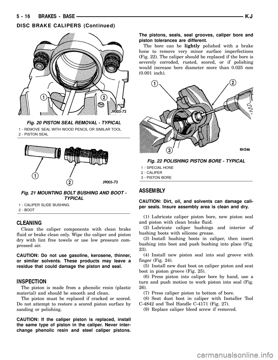
The bore can belightlypolished with a brake
hone to remove very minor surface imperfections
(Fig. 22). The caliper should be replaced if the bore is
severely corroded, rusted, scored, or if polishing
would increase bore diameter more than 0.025 mm
(0.001 inch).
ASSEMBLY
CAUTION: Dirt, oil, and solvents can damage cali-
per seals. Insure assembly area is clean and dry.
(1) Lubricate caliper piston bore, new piston seal
and piston with clean brake fluid.
(2) Lubricate caliper bushings and interior of
bushing boots with silicone grease.
(3) Install bushing boots in caliper, then insert
bushing into boot and push bushing into place (Fig.
23).
(4) Install new piston seal into seal groove with
finger (Fig. 24).
(5) Install new dust boot on caliper piston and seat
boot in piston groove (Fig. 25).
(6) Press piston into caliper bore by hand, use a
turn and push motion to work piston into seal (Fig.
26).
(7) Press caliper piston to bottom of bore.
(8) Seat dust boot in caliper with Installer Tool
C-4842 and Tool Handle C-4171 (Fig. 27).
(9) Replace caliper bleed screw if removed.
Fig. 20 PISTON SEAL REMOVAL - TYPICAL
1 - REMOVE SEAL WITH WOOD PENCIL OR SIMILAR TOOL
2 - PISTON SEAL
Fig. 21 MOUNTING BOLT BUSHING AND BOOT -
TYPICAL
1 - CALIPER SLIDE BUSHING
2 - BOOT
Fig. 22 POLISHING PISTON BORE - TYPICAL
1 - SPECIAL HONE
2 - CALIPER
3 - PISTON BORE
5 - 16 BRAKES - BASEKJ
DISC BRAKE CALIPERS (Continued)
Page 219 of 1803
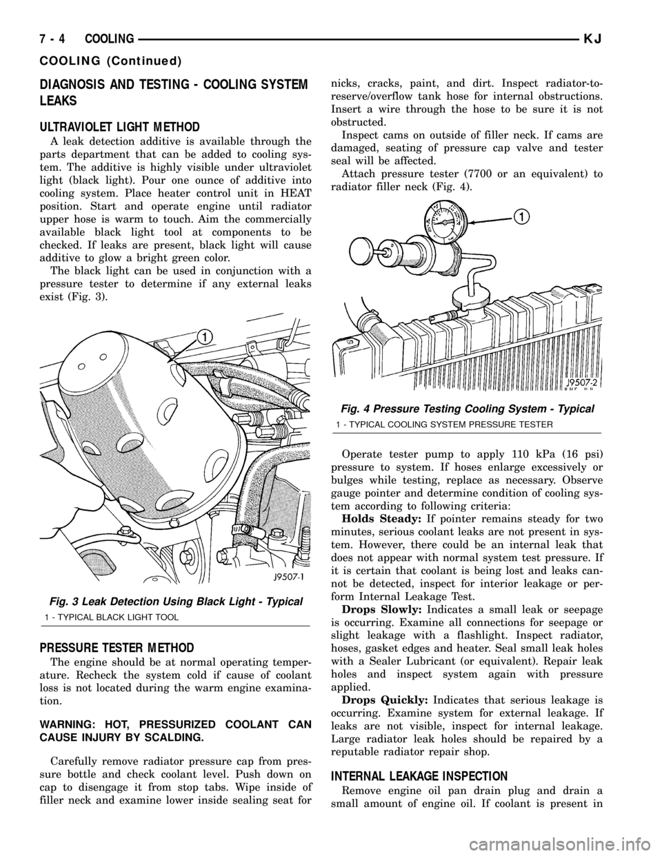
DIAGNOSIS AND TESTING - COOLING SYSTEM
LEAKS
ULTRAVIOLET LIGHT METHOD
A leak detection additive is available through the
parts department that can be added to cooling sys-
tem. The additive is highly visible under ultraviolet
light (black light). Pour one ounce of additive into
cooling system. Place heater control unit in HEAT
position. Start and operate engine until radiator
upper hose is warm to touch. Aim the commercially
available black light tool at components to be
checked. If leaks are present, black light will cause
additive to glow a bright green color.
The black light can be used in conjunction with a
pressure tester to determine if any external leaks
exist (Fig. 3).
PRESSURE TESTER METHOD
The engine should be at normal operating temper-
ature. Recheck the system cold if cause of coolant
loss is not located during the warm engine examina-
tion.
WARNING: HOT, PRESSURIZED COOLANT CAN
CAUSE INJURY BY SCALDING.
Carefully remove radiator pressure cap from pres-
sure bottle and check coolant level. Push down on
cap to disengage it from stop tabs. Wipe inside of
filler neck and examine lower inside sealing seat fornicks, cracks, paint, and dirt. Inspect radiator-to-
reserve/overflow tank hose for internal obstructions.
Insert a wire through the hose to be sure it is not
obstructed.
Inspect cams on outside of filler neck. If cams are
damaged, seating of pressure cap valve and tester
seal will be affected.
Attach pressure tester (7700 or an equivalent) to
radiator filler neck (Fig. 4).
Operate tester pump to apply 110 kPa (16 psi)
pressure to system. If hoses enlarge excessively or
bulges while testing, replace as necessary. Observe
gauge pointer and determine condition of cooling sys-
tem according to following criteria:
Holds Steady:If pointer remains steady for two
minutes, serious coolant leaks are not present in sys-
tem. However, there could be an internal leak that
does not appear with normal system test pressure. If
it is certain that coolant is being lost and leaks can-
not be detected, inspect for interior leakage or per-
form Internal Leakage Test.
Drops Slowly:Indicates a small leak or seepage
is occurring. Examine all connections for seepage or
slight leakage with a flashlight. Inspect radiator,
hoses, gasket edges and heater. Seal small leak holes
with a Sealer Lubricant (or equivalent). Repair leak
holes and inspect system again with pressure
applied.
Drops Quickly:Indicates that serious leakage is
occurring. Examine system for external leakage. If
leaks are not visible, inspect for internal leakage.
Large radiator leak holes should be repaired by a
reputable radiator repair shop.
INTERNAL LEAKAGE INSPECTION
Remove engine oil pan drain plug and drain a
small amount of engine oil. If coolant is present in
Fig. 3 Leak Detection Using Black Light - Typical
1 - TYPICAL BLACK LIGHT TOOL
Fig. 4 Pressure Testing Cooling System - Typical
1 - TYPICAL COOLING SYSTEM PRESSURE TESTER
7 - 4 COOLINGKJ
COOLING (Continued)