lug pattern JEEP LIBERTY 2002 KJ / 1.G Workshop Manual
[x] Cancel search | Manufacturer: JEEP, Model Year: 2002, Model line: LIBERTY, Model: JEEP LIBERTY 2002 KJ / 1.GPages: 1803, PDF Size: 62.3 MB
Page 92 of 1803
(4) Remove the dial indicator.
(5) Install differential case in the housing. Ensure
differential bearing cups remain on the bearings and
preload shims are seated in the housing. Tap differ-
ential case to ensure bearings cups are seated in the
housing.
(6) Install bearing caps to their original locations
and loosely install cap bolts.
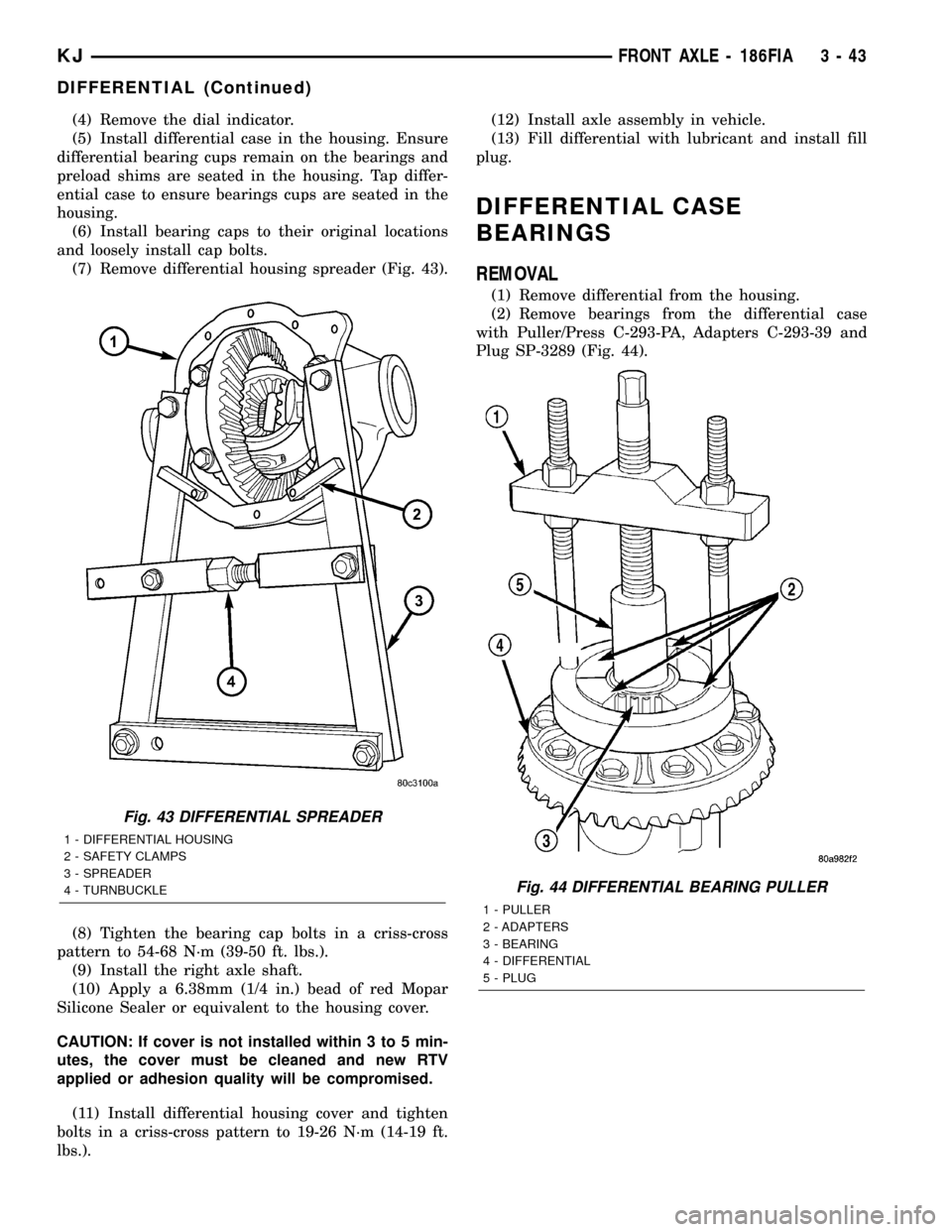
(7) Remove differential housing spreader (Fig. 43).
(8) Tighten the bearing cap bolts in a criss-cross
pattern to 54-68 N´m (39-50 ft. lbs.).
(9) Install the right axle shaft.
(10) Apply a 6.38mm (1/4 in.) bead of red Mopar
Silicone Sealer or equivalent to the housing cover.
CAUTION: If cover is not installed within 3 to 5 min-
utes, the cover must be cleaned and new RTV
applied or adhesion quality will be compromised.
(11) Install differential housing cover and tighten
bolts in a criss-cross pattern to 19-26 N´m (14-19 ft.
lbs.).(12) Install axle assembly in vehicle.
(13) Fill differential with lubricant and install fill
plug.
DIFFERENTIAL CASE
BEARINGS
REMOVAL
(1) Remove differential from the housing.
(2) Remove bearings from the differential case
with Puller/Press C-293-PA, Adapters C-293-39 and
Plug SP-3289 (Fig. 44).
Fig. 43 DIFFERENTIAL SPREADER
1 - DIFFERENTIAL HOUSING
2 - SAFETY CLAMPS
3 - SPREADER
4 - TURNBUCKLE
Fig. 44 DIFFERENTIAL BEARING PULLER
1 - PULLER
2 - ADAPTERS
3 - BEARING
4 - DIFFERENTIAL
5 - PLUG
KJFRONT AXLE - 186FIA 3 - 43
DIFFERENTIAL (Continued)
Page 123 of 1803
(6) Install the bearing caps in their original loca-
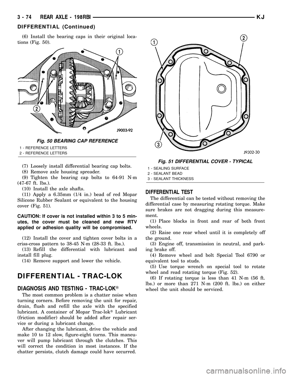
tions (Fig. 50).
(7) Loosely install differential bearing cap bolts.
(8) Remove axle housing spreader.
(9) Tighten the bearing cap bolts to 64-91 N´m
(47-67 ft. lbs.).
(10) Install the axle shafts.
(11) Apply a 6.35mm (1/4 in.) bead of red Mopar
Silicone Rubber Sealant or equivalent to the housing
cover (Fig. 51).
CAUTION: If cover is not installed within 3 to 5 min-
utes, the cover must be cleaned and new RTV
applied or adhesion quality will be compromised.
(12) Install the cover and tighten cover bolts in a
criss-cross pattern to 38-45 N´m (28-33 ft. lbs.).
(13) Refill the differential with lubricant and
install fill plug.
(14) Remove support and lower the vehicle.
DIFFERENTIAL - TRAC-LOK
DIAGNOSIS AND TESTING - TRAC-LOKT
The most common problem is a chatter noise when
turning corners. Before removing the unit for repair,
drain, flush and refill the axle with the specified
lubricant. A container of Mopar Trac-loktLubricant
(friction modifier) should be added after repair ser-
vice or during a lubricant change.
After changing the lubricant, drive the vehicle and
make 10 to 12 slow, figure-eight turns. This maneu-
ver will pump lubricant through the clutches. This
will correct the condition in most instances. If the
chatter persists, clutch damage could have occurred.
DIFFERENTIAL TEST
The differential can be tested without removing the
differential case by measuring rotating torque. Make
sure brakes are not dragging during this measure-
ment.
(1) Place blocks in front and rear of both front
wheels.
(2) Raise one rear wheel until it is completely off
the ground.
(3) Engine off, transmission in neutral, and park-
ing brake off.
(4) Remove wheel and bolt Special Tool 6790 or
equivalent tool to studs.
(5) Use torque wrench on special tool to rotate
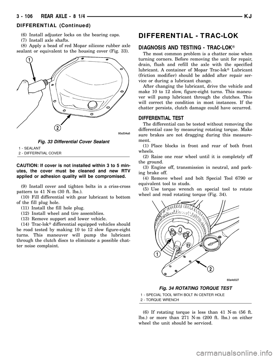
wheel and read rotating torque (Fig. 52).
(6) If rotating torque is less than 41 N´m (56 ft.
lbs.) or more than 271 N´m (200 ft. lbs.) on either
wheel the unit should be serviced.
Fig. 50 BEARING CAP REFERENCE
1 - REFERENCE LETTERS
2 - REFERENCE LETTERS
Fig. 51 DIFFERENTIAL COVER - TYPICAL
1 - SEALING SURFACE
2 - SEALANT BEAD
3 - SEALANT THICKNESS
3 - 74 REAR AXLE - 198RBIKJ
DIFFERENTIAL (Continued)
Page 155 of 1803
(6) Install adjuster locks on the bearing caps.
(7) Install axle shafts.
(8) Apply a bead of red Mopar silicone rubber axle
sealant or equivalent to the housing cover (Fig. 33).
CAUTION: If cover is not installed within 3 to 5 min-
utes, the cover must be cleaned and new RTV
applied or adhesion quality will be compromised.
(9) Install cover and tighten bolts in a criss-cross
pattern to 41 N´m (30 ft. lbs.).
(10) Fill differential with gear lubricant to bottom
of the fill plug hole.
(11) Install the fill hole plug.
(12) Install wheel and tire assemblies.
(13) Remove support and lower vehicle.
(14) Trac-loktdifferential equipped vehicles should
be road tested by making 10 to 12 slow figure-eight
turns. This maneuver will pump the lubricant
through the clutch discs to eliminate a possible chat-
ter noise complaint.DIFFERENTIAL - TRAC-LOK
DIAGNOSIS AND TESTING - TRAC-LOKT
The most common problem is a chatter noise when
turning corners. Before removing the unit for repair,
drain, flush and refill the axle with the specified
lubricant. A container of Mopar Trac-loktLubricant
(friction modifier) should be added after repair ser-
vice or during a lubricant change.
After changing the lubricant, drive the vehicle and
make 10 to 12 slow, figure-eight turns. This maneu-
ver will pump lubricant through the clutches. This
will correct the condition in most instances. If the
chatter persists, clutch damage could have occurred.
DIFFERENTIAL TEST
The differential can be tested without removing the
differential case by measuring rotating torque. Make
sure brakes are not dragging during this measure-
ment.
(1) Place blocks in front and rear of both front
wheels.
(2) Raise one rear wheel until it is completely off
the ground.
(3) Engine off, transmission in neutral, and park-
ing brake off.
(4) Remove wheel and bolt Special Tool 6790 or
equivalent tool to studs.
(5) Use torque wrench on special tool to rotate
wheel and read rotating torque (Fig. 34).
(6) If rotating torque is less than 41 N´m (56 ft.
lbs.) or more than 271 N´m (200 ft. lbs.) on either
wheel the unit should be serviced.
Fig. 33 Differential Cover Sealant
1 - SEALANT
2 - DIFFERNTIAL COVER
Fig. 34 ROTATING TORQUE TEST
1 - SPECIAL TOOL WITH BOLT IN CENTER HOLE
2 - TORQUE WRENCH
3 - 106 REAR AXLE-81/4KJ
DIFFERENTIAL (Continued)
Page 485 of 1803
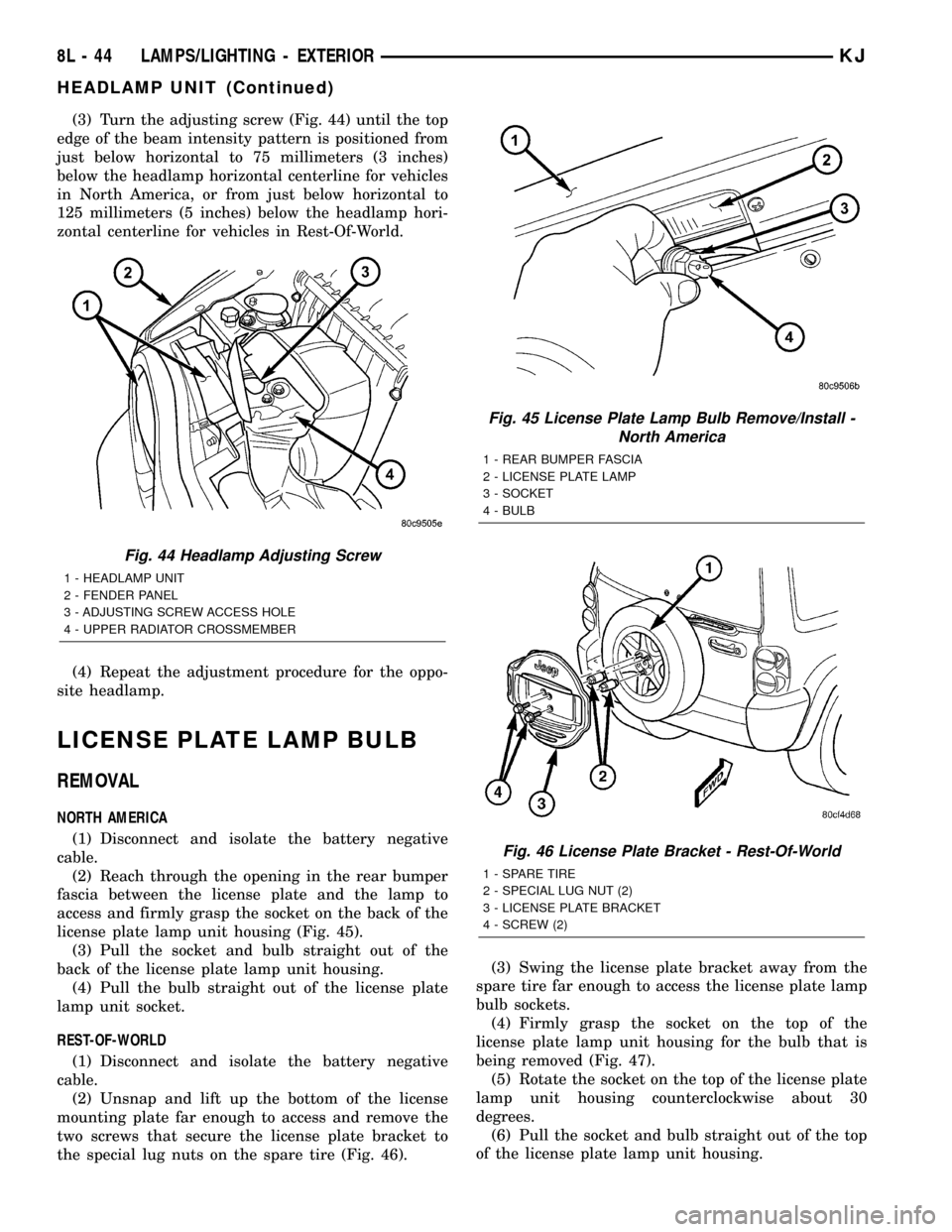
(3) Turn the adjusting screw (Fig. 44) until the top
edge of the beam intensity pattern is positioned from
just below horizontal to 75 millimeters (3 inches)
below the headlamp horizontal centerline for vehicles
in North America, or from just below horizontal to
125 millimeters (5 inches) below the headlamp hori-
zontal centerline for vehicles in Rest-Of-World.
(4) Repeat the adjustment procedure for the oppo-
site headlamp.
LICENSE PLATE LAMP BULB
REMOVAL
NORTH AMERICA
(1) Disconnect and isolate the battery negative
cable.
(2) Reach through the opening in the rear bumper
fascia between the license plate and the lamp to
access and firmly grasp the socket on the back of the
license plate lamp unit housing (Fig. 45).
(3) Pull the socket and bulb straight out of the
back of the license plate lamp unit housing.
(4) Pull the bulb straight out of the license plate
lamp unit socket.
REST-OF-WORLD
(1) Disconnect and isolate the battery negative
cable.
(2) Unsnap and lift up the bottom of the license
mounting plate far enough to access and remove the
two screws that secure the license plate bracket to
the special lug nuts on the spare tire (Fig. 46).(3) Swing the license plate bracket away from the
spare tire far enough to access the license plate lamp
bulb sockets.
(4) Firmly grasp the socket on the top of the
license plate lamp unit housing for the bulb that is
being removed (Fig. 47).
(5) Rotate the socket on the top of the license plate
lamp unit housing counterclockwise about 30
degrees.
(6) Pull the socket and bulb straight out of the top
of the license plate lamp unit housing.
Fig. 44 Headlamp Adjusting Screw
1 - HEADLAMP UNIT
2 - FENDER PANEL
3 - ADJUSTING SCREW ACCESS HOLE
4 - UPPER RADIATOR CROSSMEMBER
Fig. 45 License Plate Lamp Bulb Remove/Install -
North America
1 - REAR BUMPER FASCIA
2 - LICENSE PLATE LAMP
3 - SOCKET
4 - BULB
Fig. 46 License Plate Bracket - Rest-Of-World
1 - SPARE TIRE
2 - SPECIAL LUG NUT (2)
3 - LICENSE PLATE BRACKET
4 - SCREW (2)
8L - 44 LAMPS/LIGHTING - EXTERIORKJ
HEADLAMP UNIT (Continued)
Page 708 of 1803
ity of the headlamp and dash wire harness connector
for the washer pump/motor unit and a good ground.
There should be no continuity. If OK, go to Step 4. If
not OK, repair the shorted washer pump driver cir-
cuit between the washer pump/motor unit and the
multi-function switch as required.
(4) Check for continuity between the washer pump
driver circuit cavities of the headlamp and dash wire
harness connector for the washer pump/motor unit
and the instrument panel wire harness connector for
the multi-function switch (Connector C-2). There
should be continuity. If OK, go to Step 5. If not OK,
repair the open washer pump driver circuit between
the washer pump/motor unit and the multi-function
switch as required.
(5) Check for continuity between the washer pump
sense circuit cavity of the headlamp and dash wire
harness connector for the washer pump/motor unit
and a good ground. There should be no continuity. If
OK, go to Step 6. If not OK, repair the shorted
washer pump sense circuit between the washer
pump/motor unit and the multi-function switch as
required.
(6) Check for continuity between the washer pump
sense circuit cavities of the headlamp and dash wire
harness connector for the washer pump/motor unit
and the instrument panel wire harness connector for
the multi-function switch (Connector C-2). There
should be continuity. If OK, replace the faulty washer
pump/motor unit. If not OK, repair the open washer
pump sense circuit between the washer pump/motor
unit and the multi-function switch as required.
CLEANING - FRONT WIPER & WASHER
SYSTEM
FRONT WIPER SYSTEM
The squeegees of wiper blades exposed to the ele-
ments for a long time tend to lose their wiping effec-
tiveness. Periodic cleaning of the squeegees is
suggested to remove any deposits of salt or road film.
The wiper blades, arms, and windshield glass should
only be cleaned using a sponge or soft cloth and
windshield washer fluid, a mild detergent, or a non-
abrasive cleaner. If the wiper blades continue to
leave streaks, smears, hazing, or beading on the
glass after thorough cleaning of the squeegees and
the glass, the entire wiper blade assembly must be
replaced.
CAUTION: Protect the rubber squeegees of the
wiper blades from any petroleum-based cleaners,
solvents, or contaminants. These products can rap-
idly deteriorate the rubber squeegees.FRONT WASHER SYSTEM
If the washer system is contaminated with foreign
material, drain the washer reservoir by removing the
washer pump/motor from the reservoir. Clean foreign
material from the inside of the washer pump/motor
inlet filter screen and the washer reservoir using
clean washer fluid, a mild detergent, or a non-abra-
sive cleaner. Flush foreign material from the washer
system plumbing by first disconnecting the washer
hoses from the washer nozzles, then running the
washer pump/motor to run clean washer fluid or
water through the system. Plugged or restricted
washer nozzles should be carefully back-flushed
using compressed air. If the washer nozzle obstruc-
tion cannot be cleared, replace the washer nozzle.
CAUTION: Never introduce petroleum-based clean-
ers, solvents, or contaminants into the washer sys-
tem. These products can rapidly deteriorate the
rubber seals and hoses of the washer system, as
well as the rubber squeegees of the wiper blades.
CAUTION: Never use compressed air to flush the
washer system plumbing. Compressed air pres-
sures are too great for the washer system plumbing
components and will result in further system dam-
age. Never use sharp instruments to clear a
plugged washer nozzle or damage to the nozzle ori-
fice and improper nozzle spray patterns will result.
INSPECTION - FRONT WIPER & WASHER
SYSTEM
FRONT WIPER SYSTEM
The front wiper blades and wiper arms should be
inspected periodically, not just when wiper perfor-
mance problems are experienced. This inspection
should include the following points:
(1) Inspect the wiper arms for any indications of
damage, or contamination. If the wiper arms are con-
taminated with any foreign material, clean them as
required. (Refer to 8 - ELECTRICAL/FRONT WIP-
ERS/WASHERS - CLEANING). If a wiper arm is
damaged or corrosion is evident, replace the wiper
arm with a new unit. Do not attempt to repair a
wiper arm that is damaged or corroded.
(2) Carefully lift the wiper blade off of the glass.
Note the action of the wiper arm hinge. The wiper
arm should pivot freely at the hinge, but with no lat-
eral looseness evident. If there is any binding evident
in the wiper arm hinge, or there is evident lateral
play in the wiper arm hinge, replace the wiper arm.
KJFRONT WIPERS/WASHERS 8R - 7
FRONT WIPERS/WASHERS (Continued)
Page 734 of 1803
REAR WASHER SYSTEM
If the washer system is contaminated with foreign
material, drain the washer reservoir by removing the
washer pump/motor from the reservoir. Clean foreign
material from the inside of the washer pump/motor
inlet filter screen and the washer reservoir using
clean washer fluid, a mild detergent, or a non-abra-
sive cleaner. Flush foreign material from the washer
system plumbing by first disconnecting the washer
hose from the washer nozzle, then running the
washer pump/motor to run clean washer fluid or
water through the system. A plugged or restricted
washer nozzle should be carefully back-flushed using
compressed air. If the washer nozzle obstruction can-
not be cleared, replace the washer nozzle.
CAUTION: Never introduce petroleum-based clean-
ers, solvents, or contaminants into the washer sys-
tem. These products can rapidly deteriorate the
rubber seals and hoses of the washer system, as
well as the rubber squeegee of the wiper blade.
CAUTION: Never use compressed air to flush the
washer system plumbing. Compressed air pres-
sures are too great for the washer system plumbing
components and will result in further system dam-
age. Never use sharp instruments to clear a
plugged washer nozzle or damage to the nozzle ori-
fice and improper nozzle spray patterns will result.
INSPECTION - REAR WIPER & WASHER
SYSTEM
REAR WIPER SYSTEM
The rear wiper blade and wiper arm should be
inspected periodically, not just when wiper perfor-
mance problems are experienced. This inspection
should include the following points:
(1) Inspect the wiper arm for any indications of
damage, or contamination. If the wiper arm is con-
taminated with any foreign material, clean as
required. (Refer to 8 - ELECTRICAL/REAR WIPERS/
WASHERS - CLEANING). If a wiper arm is damaged
or corrosion is evident, replace the wiper arm with a
new unit. Do not attempt to repair a wiper arm that
is damaged or corroded.
(2) Carefully lift the wiper arm off of the park
ramp. Note the action of the wiper arm hinge. The
wiper arm should pivot freely at the hinge, but with
no lateral looseness evident. If there is any binding
evident in the wiper arm hinge, or there is evident
lateral play in the wiper arm hinge, replace the
wiper arm.CAUTION: Do not allow the wiper arm to spring
back against the glass without the wiper blade in
place or the glass may be damaged.
(3) Once proper hinge action of the wiper arm is
confirmed, check the hinge for proper spring tension.
The spring tension of the wiper arm should be suffi-
cient to cause the rubber squeegee to conform to the
curvature of the glass. Replace a wiper arm if it has
low or no spring tension.
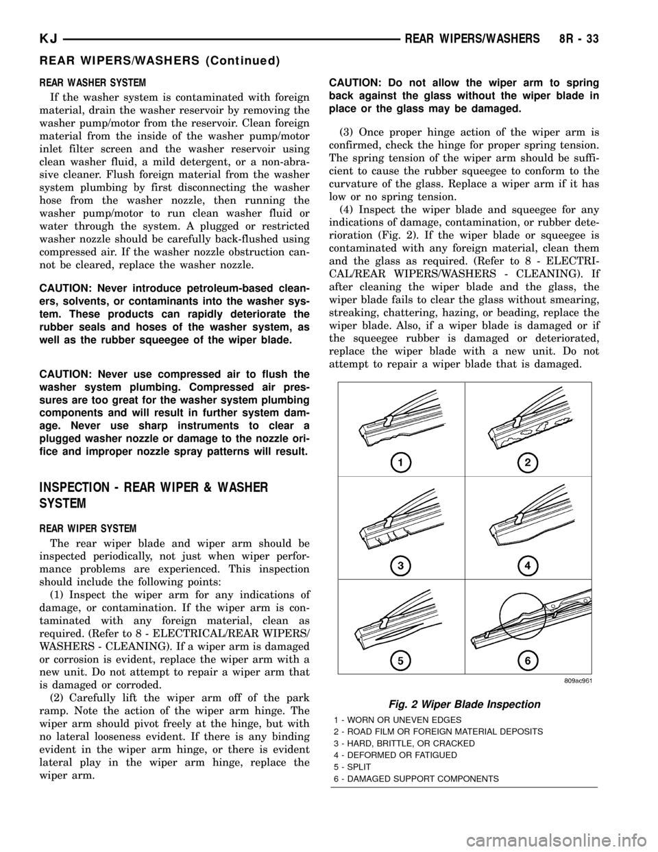
(4) Inspect the wiper blade and squeegee for any
indications of damage, contamination, or rubber dete-
rioration (Fig. 2). If the wiper blade or squeegee is
contaminated with any foreign material, clean them
and the glass as required. (Refer to 8 - ELECTRI-
CAL/REAR WIPERS/WASHERS - CLEANING). If
after cleaning the wiper blade and the glass, the
wiper blade fails to clear the glass without smearing,
streaking, chattering, hazing, or beading, replace the
wiper blade. Also, if a wiper blade is damaged or if
the squeegee rubber is damaged or deteriorated,
replace the wiper blade with a new unit. Do not
attempt to repair a wiper blade that is damaged.
Fig. 2 Wiper Blade Inspection
1 - WORN OR UNEVEN EDGES
2 - ROAD FILM OR FOREIGN MATERIAL DEPOSITS
3 - HARD, BRITTLE, OR CRACKED
4 - DEFORMED OR FATIGUED
5 - SPLIT
6 - DAMAGED SUPPORT COMPONENTS
KJREAR WIPERS/WASHERS 8R - 33
REAR WIPERS/WASHERS (Continued)
Page 1255 of 1803
Once the block has been completely cleaned, apply
Loctite PST pipe sealant with Teflon 592 to the
threads of the front and rear oil galley plugs. Tighten
the plugs to 34 N´m (25 ft. lbs.) torque.
INSPECTION
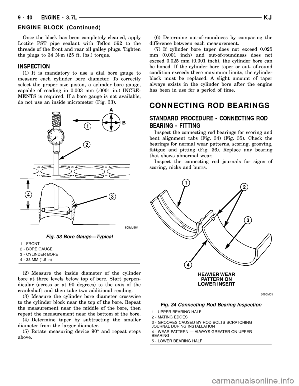
(1) It is mandatory to use a dial bore gauge to
measure each cylinder bore diameter. To correctly
select the proper size piston, a cylinder bore gauge,
capable of reading in 0.003 mm (.0001 in.) INCRE-
MENTS is required. If a bore gauge is not available,
do not use an inside micrometer (Fig. 33).
(2) Measure the inside diameter of the cylinder
bore at three levels below top of bore. Start perpen-
dicular (across or at 90 degrees) to the axis of the
crankshaft and then take two additional reading.
(3) Measure the cylinder bore diameter crosswise
to the cylinder block near the top of the bore. Repeat
the measurement near the middle of the bore, then
repeat the measurement near the bottom of the bore.
(4) Determine taper by subtracting the smaller
diameter from the larger diameter.
(5) Rotate measuring device 90É and repeat steps
above.(6) Determine out-of-roundness by comparing the
difference between each measurement.
(7) If cylinder bore taper does not exceed 0.025
mm (0.001 inch) and out-of-roundness does not
exceed 0.025 mm (0.001 inch), the cylinder bore can
be honed. If the cylinder bore taper or out- of-round
condition exceeds these maximum limits, the cylinder
block must be replaced. A slight amount of taper
always exists in the cylinder bore after the engine
has been in use for a period of time.
CONNECTING ROD BEARINGS
STANDARD PROCEDURE - CONNECTING ROD
BEARING - FITTING
Inspect the connecting rod bearings for scoring and
bent alignment tabs (Fig. 34) (Fig. 35). Check the
bearings for normal wear patterns, scoring, grooving,
fatigue and pitting (Fig. 36). Replace any bearing
that shows abnormal wear.
Inspect the connecting rod journals for signs of
scoring, nicks and burrs.
Fig. 33 Bore GaugeÐTypical
1 - FRONT
2 - BORE GAUGE
3 - CYLINDER BORE
4 - 38 MM (1.5 in)
Fig. 34 Connecting Rod Bearing Inspection
1 - UPPER BEARING HALF
2 - MATING EDGES
3 - GROOVES CAUSED BY ROD BOLTS SCRATCHING
JOURNAL DURING INSTALLATION
4 - WEAR PATTERN Ð ALWAYS GREATER ON UPPER
BEARING
5 - LOWER BEARING HALF
9 - 40 ENGINE - 3.7LKJ
ENGINE BLOCK (Continued)
Page 1275 of 1803
DIAGNOSIS AND TESTING
DIAGNOSIS AND TESTING - ENGINE OIL LEAK
Begin with a thorough visual inspection of the
engine, particularly at the area of the suspected leak.
If an oil leak source is not readily identifiable, the
following steps should be followed:
(1) Do not clean or degrease the engine at this
time because some solvents may cause rubber to
swell, temporarily stopping the leak.
(2) Add an oil soluble dye (use as recommended by
manufacturer). Start the engine and let idle for
approximately 15 minutes. Check the oil dipstick to
make sure the dye is thoroughly mixed as indicated
with a bright yellow color under a black light.
(3) Using a black light, inspect the entire engine
for fluorescent dye, particularly at the suspected area
of oil leak. If the oil leak is found and identified,
repair per service manual instructions.
(4) If dye is not observed, drive the vehicle at var-
ious speeds for approximately 24km (15 miles), and
repeat inspection.If the oil leak source is not pos-
itively identified at this time, proceed with the air
leak detection test method.
Air Leak Detection Test Method
(1) Disconnect the breather cap to air cleaner hose
at the breather cap end. Cap or plug breather cap
nipple.
(2) Remove the PCV valve from the cylinder head
cover. Cap or plug the PCV valve grommet.
(3) Attach an air hose with pressure gauge and
regulator to the dipstick tube.
CAUTION: Do not subject the engine assembly to
more than 20.6 kpa (3 PSI) of test pressure.
(4) Gradually apply air pressure from 1 psi to 2.5
psi maximum while applying soapy water at the sus-
pected source. Adjust the regulator to the suitable
test pressure that provide the best bubbles which
will pinpoint the leak source. If the oil leak is
detected and identified, repair per service manual
procedures.
(5) If the leakage occurs at the rear oil seal area,
refer to the section, Inspection for Rear Seal Area
Leak.
(6) If no leaks are detected, turn off the air supply
and remove the air hose and all plugs and caps.
Install the PCV valve and breather cap hose.
(7) Clean the oil off the suspect oil leak area using
a suitable solvent. Drive the vehicle at various
speeds approximately 24 km (15 miles). Inspect the
engine for signs of an oil leak by using a black light.
INSPECTION FOR REAR SEAL AREA LEAKS
Since it is sometimes difficult to determine the
source of an oil leak in the rear seal area of the
engine, a more involved inspection is necessary. The
following steps should be followed to help pinpoint
the source of the leak.
If the leakage occurs at the crankshaft rear oil seal
area:
(1) Disconnect the battery.
(2) Raise the vehicle.
(3) Remove torque converter or clutch housing
cover and inspect rear of block for evidence of oil.
Use a black light to check for the oil leak:
(a) Circular spray pattern generally indicates
seal leakage or crankshaft damage.
(b) Where leakage tends to run straight down,
possible causes are a porous block, camshaft bore
cup plugs oil galley pipe plugs, oil filter runoff, and
main bearing cap to cylinder block mating sur-
faces.
(4) If no leaks are detected, pressurize the crank-
case as outlined in the, Inspection (Engine oil Leaks
in general)
CAUTION: Do not exceed 20.6 kPa (3 psi).
(5) If the leak is not detected, very slowly turn the
crankshaft and watch for leakage. If a leak is
detected between the crankshaft and seal while
slowly turning the crankshaft, it is possible the
crankshaft seal surface is damaged. The seal area on
the crankshaft could have minor nicks or scratches
that can be polished out with emery cloth.
CAUTION: Use extreme caution when crankshaft
polishing is necessary to remove minor nicks and
scratches. The crankshaft seal flange is especially
machined to complement the function of the rear oil
seal.
(6) For bubbles that remain steady with shaft
rotation, no further inspection can be done until dis-
assembled.
DIAGNOSIS AND TESTING - ENGINE OIL
PRESSURE
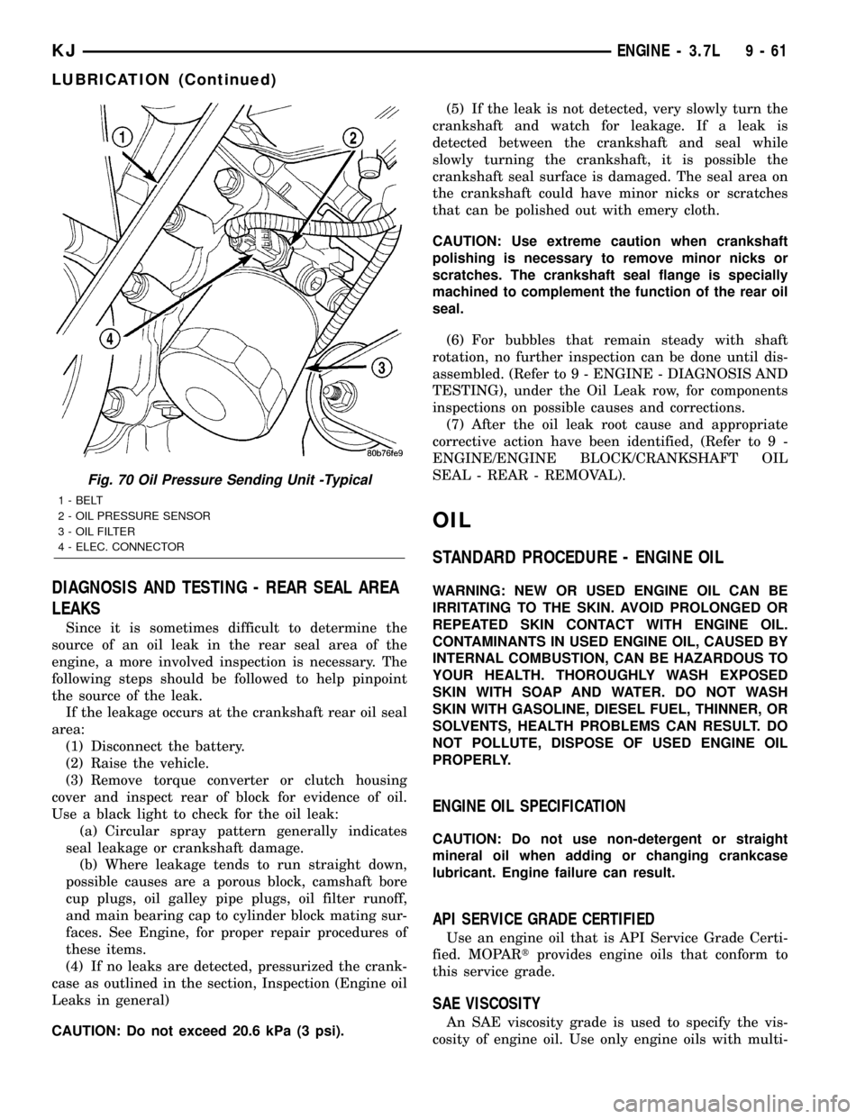
(1) Remove oil pressure sending unit (Fig. 70)and
install gauge assembly C-3292.
(2) Run engine until thermostat opens.
(3) Oil Pressure:
²Curb IdleÐ25 Kpa (4 psi) minimum
²3000 rpmÐ170 - 550 KPa (25 - 80 psi)
(4) If oil pressure is 0 at idle, shut off engine.
Check for a clogged oil pick-up screen or a pressure
relief valve stuck open.
9 - 60 ENGINE - 3.7LKJ
LUBRICATION (Continued)
Page 1276 of 1803
DIAGNOSIS AND TESTING - REAR SEAL AREA
LEAKS
Since it is sometimes difficult to determine the
source of an oil leak in the rear seal area of the
engine, a more involved inspection is necessary. The
following steps should be followed to help pinpoint
the source of the leak.
If the leakage occurs at the crankshaft rear oil seal
area:
(1) Disconnect the battery.
(2) Raise the vehicle.
(3) Remove torque converter or clutch housing
cover and inspect rear of block for evidence of oil.
Use a black light to check for the oil leak:
(a) Circular spray pattern generally indicates
seal leakage or crankshaft damage.
(b) Where leakage tends to run straight down,
possible causes are a porous block, camshaft bore
cup plugs, oil galley pipe plugs, oil filter runoff,
and main bearing cap to cylinder block mating sur-
faces. See Engine, for proper repair procedures of
these items.
(4) If no leaks are detected, pressurized the crank-
case as outlined in the section, Inspection (Engine oil
Leaks in general)
CAUTION: Do not exceed 20.6 kPa (3 psi).(5) If the leak is not detected, very slowly turn the
crankshaft and watch for leakage. If a leak is
detected between the crankshaft and seal while
slowly turning the crankshaft, it is possible the
crankshaft seal surface is damaged. The seal area on
the crankshaft could have minor nicks or scratches
that can be polished out with emery cloth.
CAUTION: Use extreme caution when crankshaft
polishing is necessary to remove minor nicks or
scratches. The crankshaft seal flange is specially
machined to complement the function of the rear oil
seal.
(6) For bubbles that remain steady with shaft
rotation, no further inspection can be done until dis-
assembled. (Refer to 9 - ENGINE - DIAGNOSIS AND
TESTING), under the Oil Leak row, for components
inspections on possible causes and corrections.
(7) After the oil leak root cause and appropriate
corrective action have been identified, (Refer to 9 -
ENGINE/ENGINE BLOCK/CRANKSHAFT OIL
SEAL - REAR - REMOVAL).
OIL
STANDARD PROCEDURE - ENGINE OIL
WARNING: NEW OR USED ENGINE OIL CAN BE
IRRITATING TO THE SKIN. AVOID PROLONGED OR
REPEATED SKIN CONTACT WITH ENGINE OIL.
CONTAMINANTS IN USED ENGINE OIL, CAUSED BY
INTERNAL COMBUSTION, CAN BE HAZARDOUS TO
YOUR HEALTH. THOROUGHLY WASH EXPOSED
SKIN WITH SOAP AND WATER. DO NOT WASH
SKIN WITH GASOLINE, DIESEL FUEL, THINNER, OR
SOLVENTS, HEALTH PROBLEMS CAN RESULT. DO
NOT POLLUTE, DISPOSE OF USED ENGINE OIL
PROPERLY.
ENGINE OIL SPECIFICATION
CAUTION: Do not use non-detergent or straight
mineral oil when adding or changing crankcase
lubricant. Engine failure can result.
API SERVICE GRADE CERTIFIED
Use an engine oil that is API Service Grade Certi-
fied. MOPARtprovides engine oils that conform to
this service grade.
SAE VISCOSITY
An SAE viscosity grade is used to specify the vis-
cosity of engine oil. Use only engine oils with multi-
Fig. 70 Oil Pressure Sending Unit -Typical
1 - BELT
2 - OIL PRESSURE SENSOR
3 - OIL FILTER
4 - ELEC. CONNECTOR
KJENGINE - 3.7L 9 - 61
LUBRICATION (Continued)
Page 1301 of 1803
(7) Crank engine until maximum pressure is
reached on gage. Record this pressure as #1 cylinder
pressure.
(8) Repeat the previous step for all remaining cyl-
inders.
(9) Compression should not be less than 689 kPa
(100 psi) and not vary more than 25 percent from cyl-
inder to cylinder.
(10) If one or more cylinders have abnormally low
compression pressures, repeat the compression test.
(11) If the same cylinder or cylinders repeat an
abnormally low reading on the second compression
test, it could indicate the existence of a problem in
the cylinder in question.The recommended com-
pression pressures are to be used only as a
guide to diagnosing engine problems. An engine
should not be disassembled to determine the
cause of low compression unless some malfunc-
tion is present.
DIAGNOSIS AND TESTING - ENGINE OIL LEAK
INSPECTION
Begin with a thorough visual inspection of the
engine, particularly at the area of the suspected leak.
If an oil leak source is not readily identifiable, the
following steps should be followed:
(1) Do not clean or degrease the engine at this
time because some solvents may cause rubber to
swell, temporarily stopping the leak.
(2) Add an oil soluble dye (use as recommended by
manufacturer). Start the engine and let idle for
approximately 15 minutes. Check the oil dipstick to
make sure the dye is thoroughly mixed as indicated
with a bright yellow color under a black light.
(3) Using a black light, inspect the entire engine
for fluorescent dye, particularly at the suspected area
of oil leak. If the oil leak is found and identified,
repair as necessary.
(4) If dye is not observed, drive the vehicle at var-
ious speeds for approximately 24 km (15 miles), and
repeat inspection.
(5)If the oil leak source is not positively
identified at this time, proceed with the air leak
detection test method as follows:
²Disconnect the fresh air hose (make-up air) at
the cylinder head cover and plug or cap the nipple on
the cover.
²Remove the PCV valve hose from the cylinder
head cover. Cap or plug the PCV valve nipple on the
cover.
²Attach an air hose with pressure gauge and reg-
ulator to the dipstick tube.
CAUTION: Do not subject the engine assembly to
more than 20.6 kpa (3 PSI) of test pressure.²Gradually apply air pressure from 1 psi to 2.5
psi maximum while applying soapy water at the sus-
pected source. Adjust the regulator to the suitable
test pressure that provides the best bubbles which
will pinpoint the leak source. If the oil leak is
detected and identified, repair per service manual
procedures.
²If the leakage occurs at the crankshaft rear oil
seal area, refer to the section, Inspection for Rear
Seal Area Leak.
(6) If no leaks are detected, turn off the air supply.
Remove the air hose, all plugs, and caps. Install the
PCV valve and fresh air hose (make-up air). Proceed
to next step.
(7) Clean the oil off the suspect oil leak area using
a suitable solvent. Drive the vehicle at various
speeds approximately 24 km (15 miles). Inspect the
engine for signs of an oil leak by using a black light.
NOTE: If oil leakage is observed at the dipstick tube
to block location; remove the tube, clean and reseal
using MoparTStud & Bearing Mount (press fit tube
applications only), and for O-ring style tubes,
remove tube and replace the O-ring seal.
INSPECTION FOR REAR SEAL AREA LEAKS
Since it is sometimes difficult to determine the
source of an oil leak in the rear seal area of the
engine, a more involved inspection is necessary. The
following steps should be followed to help pinpoint
the source of the leak.
If the leakage occurs at the crankshaft rear oil seal
area:
(1) Disconnect the battery.
(2) Raise the vehicle.
(3) Remove torque converter or clutch housing
cover and inspect rear of block for evidence of oil.
Use a black light to check for the oil leak. If a leak is
present in this area, remove transmission for further
inspection.
(a) Circular spray pattern generally indicates
seal leakage or crankshaft damage.
(b) Where leakage tends to run straight down,
possible causes are a porous block, oil gallery cup
plug, bedplate to cylinder block mating surfaces
and seal bore. See proper repair procedures for
these items.
(4) If no leaks are detected, pressurize the crank-
case as previously described.
CAUTION: Do not exceed 20.6 kPa (3 psi).
(5) If the leak is not detected, very slowly turn the
crankshaft and watch for leakage. If a leak is
detected between the crankshaft and seal while
slowly turning the crankshaft, it is possible the
9s - 4 ENGINEKJ
ENGINE - 2.4L (Continued)