replace head gasket JEEP LIBERTY 2002 KJ / 1.G Workshop Manual
[x] Cancel search | Manufacturer: JEEP, Model Year: 2002, Model line: LIBERTY, Model: JEEP LIBERTY 2002 KJ / 1.GPages: 1803, PDF Size: 62.3 MB
Page 223 of 1803
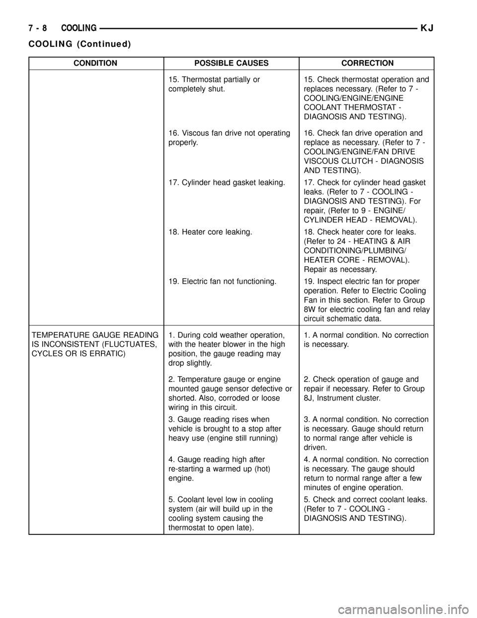
CONDITION POSSIBLE CAUSES CORRECTION
15. Thermostat partially or
completely shut.15. Check thermostat operation and
replaces necessary. (Refer to 7 -
COOLING/ENGINE/ENGINE
COOLANT THERMOSTAT -
DIAGNOSIS AND TESTING).
16. Viscous fan drive not operating
properly.16. Check fan drive operation and
replace as necessary. (Refer to 7 -
COOLING/ENGINE/FAN DRIVE
VISCOUS CLUTCH - DIAGNOSIS
AND TESTING).
17. Cylinder head gasket leaking. 17. Check for cylinder head gasket
leaks. (Refer to 7 - COOLING -
DIAGNOSIS AND TESTING). For
repair, (Refer to 9 - ENGINE/
CYLINDER HEAD - REMOVAL).
18. Heater core leaking. 18. Check heater core for leaks.
(Refer to 24 - HEATING & AIR
CONDITIONING/PLUMBING/
HEATER CORE - REMOVAL).
Repair as necessary.
19. Electric fan not functioning. 19. Inspect electric fan for proper
operation. Refer to Electric Cooling
Fan in this section. Refer to Group
8W for electric cooling fan and relay
circuit schematic data.
TEMPERATURE GAUGE READING
IS INCONSISTENT (FLUCTUATES,
CYCLES OR IS ERRATIC)1. During cold weather operation,
with the heater blower in the high
position, the gauge reading may
drop slightly.1. A normal condition. No correction
is necessary.
2. Temperature gauge or engine
mounted gauge sensor defective or
shorted. Also, corroded or loose
wiring in this circuit.2. Check operation of gauge and
repair if necessary. Refer to Group
8J, Instrument cluster.
3. Gauge reading rises when
vehicle is brought to a stop after
heavy use (engine still running)3. A normal condition. No correction
is necessary. Gauge should return
to normal range after vehicle is
driven.
4. Gauge reading high after
re-starting a warmed up (hot)
engine.4. A normal condition. No correction
is necessary. The gauge should
return to normal range after a few
minutes of engine operation.
5. Coolant level low in cooling
system (air will build up in the
cooling system causing the
thermostat to open late).5. Check and correct coolant leaks.
(Refer to 7 - COOLING -
DIAGNOSIS AND TESTING).
7 - 8 COOLINGKJ
COOLING (Continued)
Page 224 of 1803
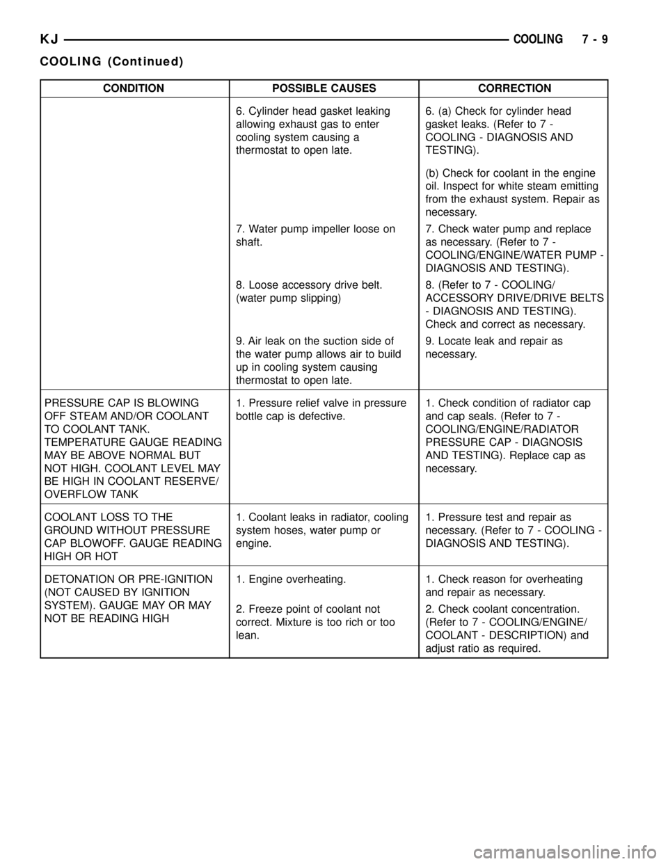
CONDITION POSSIBLE CAUSES CORRECTION
6. Cylinder head gasket leaking
allowing exhaust gas to enter
cooling system causing a
thermostat to open late.6. (a) Check for cylinder head
gasket leaks. (Refer to 7 -
COOLING - DIAGNOSIS AND
TESTING).
(b) Check for coolant in the engine
oil. Inspect for white steam emitting
from the exhaust system. Repair as
necessary.
7. Water pump impeller loose on
shaft.7. Check water pump and replace
as necessary. (Refer to 7 -
COOLING/ENGINE/WATER PUMP -
DIAGNOSIS AND TESTING).
8. Loose accessory drive belt.
(water pump slipping)8. (Refer to 7 - COOLING/
ACCESSORY DRIVE/DRIVE BELTS
- DIAGNOSIS AND TESTING).
Check and correct as necessary.
9. Air leak on the suction side of
the water pump allows air to build
up in cooling system causing
thermostat to open late.9. Locate leak and repair as
necessary.
PRESSURE CAP IS BLOWING
OFF STEAM AND/OR COOLANT
TO COOLANT TANK.
TEMPERATURE GAUGE READING
MAY BE ABOVE NORMAL BUT
NOT HIGH. COOLANT LEVEL MAY
BE HIGH IN COOLANT RESERVE/
OVERFLOW TANK1. Pressure relief valve in pressure
bottle cap is defective.1. Check condition of radiator cap
and cap seals. (Refer to 7 -
COOLING/ENGINE/RADIATOR
PRESSURE CAP - DIAGNOSIS
AND TESTING). Replace cap as
necessary.
COOLANT LOSS TO THE
GROUND WITHOUT PRESSURE
CAP BLOWOFF. GAUGE READING
HIGH OR HOT1. Coolant leaks in radiator, cooling
system hoses, water pump or
engine.1. Pressure test and repair as
necessary. (Refer to 7 - COOLING -
DIAGNOSIS AND TESTING).
DETONATION OR PRE-IGNITION
(NOT CAUSED BY IGNITION
SYSTEM). GAUGE MAY OR MAY
NOT BE READING HIGH1. Engine overheating. 1. Check reason for overheating
and repair as necessary.
2. Freeze point of coolant not
correct. Mixture is too rich or too
lean.2. Check coolant concentration.
(Refer to 7 - COOLING/ENGINE/
COOLANT - DESCRIPTION) and
adjust ratio as required.
KJCOOLING 7 - 9
COOLING (Continued)
Page 254 of 1803
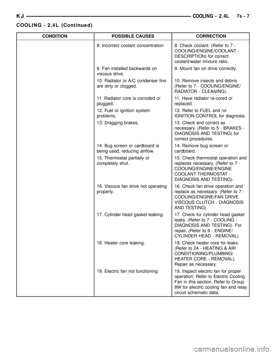
CONDITION POSSIBLE CAUSES CORRECTION
8. Incorrect coolant concentration 8. Check coolant. (Refer to 7 -
COOLING/ENGINE/COOLANT -
DESCRIPTION) for correct
coolant/water mixture ratio.
9. Fan installed backwards on
viscous drive.9. Mount fan on drive correctly.
10. Radiator or A/C condenser fins
are dirty or clogged.10. Remove insects and debris.
(Refer to 7 - COOLING/ENGINE/
RADIATOR - CLEANING).
11. Radiator core is corroded or
plugged.11. Have radiator re-cored or
replaced.
12. Fuel or ignition system
problems.12. Refer to FUEL and /or
IGNITION CONTROL for diagnosis.
13. Dragging brakes. 13. Check and correct as
necessary. (Refer to 5 - BRAKES -
DIAGNOSIS AND TESTING) for
correct procedures.
14. Bug screen or cardboard is
being used, reducing airflow.14. Remove bug screen or
cardboard.
15. Thermostat partially or
completely shut.15. Check thermostat operation and
replaces necessary. (Refer to 7 -
COOLING/ENGINE/ENGINE
COOLANT THERMOSTAT -
DIAGNOSIS AND TESTING).
16. Viscous fan drive not operating
properly.16. Check fan drive operation and
replace as necessary. (Refer to 7 -
COOLING/ENGINE/FAN DRIVE
VISCOUS CLUTCH - DIAGNOSIS
AND TESTING).
17. Cylinder head gasket leaking. 17. Check for cylinder head gasket
leaks. (Refer to 7 - COOLING -
DIAGNOSIS AND TESTING). For
repair, (Refer to 9 - ENGINE/
CYLINDER HEAD - REMOVAL).
18. Heater core leaking. 18. Check heater core for leaks.
(Refer to 24 - HEATING & AIR
CONDITIONING/PLUMBING/
HEATER CORE - REMOVAL).
Repair as necessary.
19. Electric fan not functioning. 19. Inspect electric fan for proper
operation. Refer to Electric Cooling
Fan in this section. Refer to Group
8W for electric cooling fan and relay
circuit schematic data.
KJCOOLING - 2.4L7s-7
COOLING - 2.4L (Continued)
Page 255 of 1803
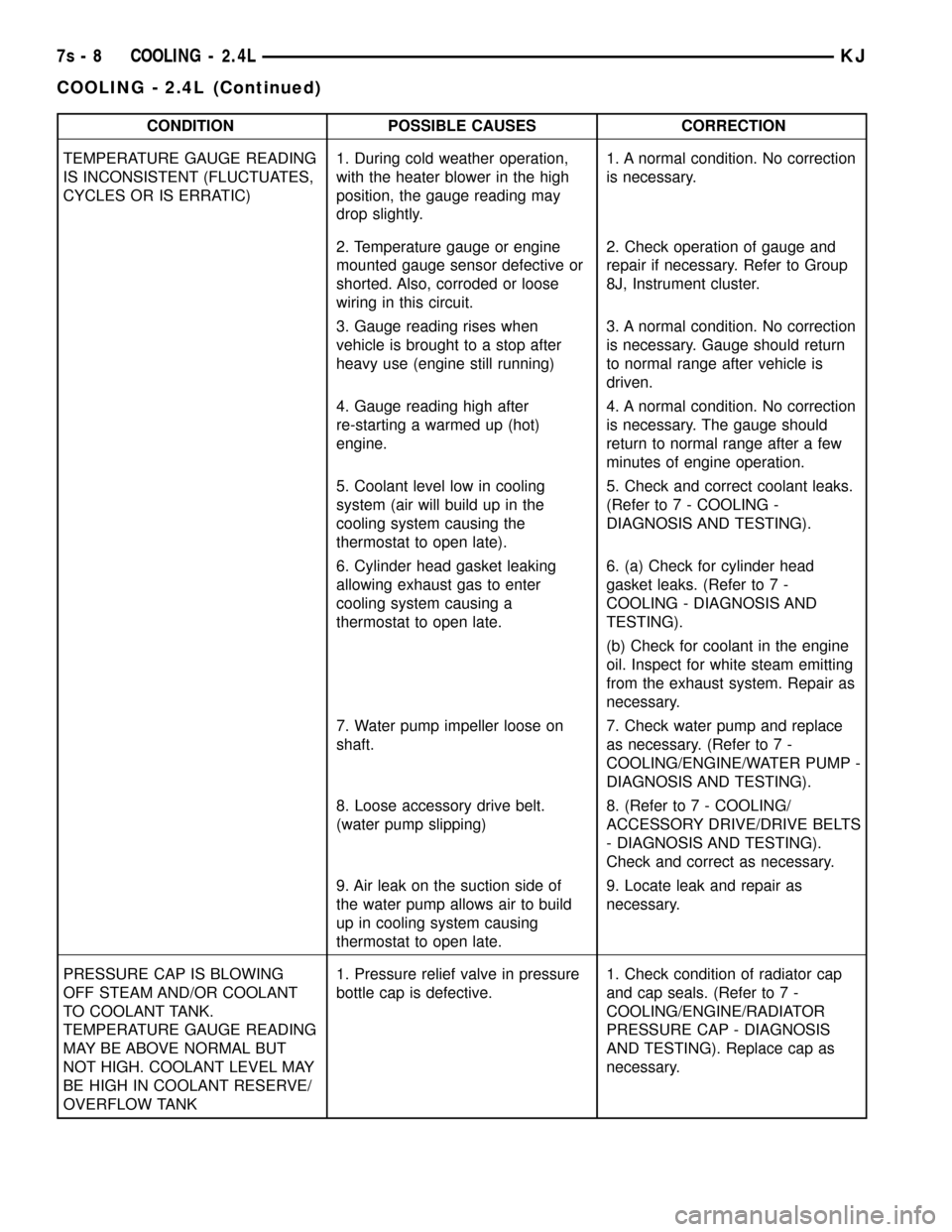
CONDITION POSSIBLE CAUSES CORRECTION
TEMPERATURE GAUGE READING
IS INCONSISTENT (FLUCTUATES,
CYCLES OR IS ERRATIC)1. During cold weather operation,
with the heater blower in the high
position, the gauge reading may
drop slightly.1. A normal condition. No correction
is necessary.
2. Temperature gauge or engine
mounted gauge sensor defective or
shorted. Also, corroded or loose
wiring in this circuit.2. Check operation of gauge and
repair if necessary. Refer to Group
8J, Instrument cluster.
3. Gauge reading rises when
vehicle is brought to a stop after
heavy use (engine still running)3. A normal condition. No correction
is necessary. Gauge should return
to normal range after vehicle is
driven.
4. Gauge reading high after
re-starting a warmed up (hot)
engine.4. A normal condition. No correction
is necessary. The gauge should
return to normal range after a few
minutes of engine operation.
5. Coolant level low in cooling
system (air will build up in the
cooling system causing the
thermostat to open late).5. Check and correct coolant leaks.
(Refer to 7 - COOLING -
DIAGNOSIS AND TESTING).
6. Cylinder head gasket leaking
allowing exhaust gas to enter
cooling system causing a
thermostat to open late.6. (a) Check for cylinder head
gasket leaks. (Refer to 7 -
COOLING - DIAGNOSIS AND
TESTING).
(b) Check for coolant in the engine
oil. Inspect for white steam emitting
from the exhaust system. Repair as
necessary.
7. Water pump impeller loose on
shaft.7. Check water pump and replace
as necessary. (Refer to 7 -
COOLING/ENGINE/WATER PUMP -
DIAGNOSIS AND TESTING).
8. Loose accessory drive belt.
(water pump slipping)8. (Refer to 7 - COOLING/
ACCESSORY DRIVE/DRIVE BELTS
- DIAGNOSIS AND TESTING).
Check and correct as necessary.
9. Air leak on the suction side of
the water pump allows air to build
up in cooling system causing
thermostat to open late.9. Locate leak and repair as
necessary.
PRESSURE CAP IS BLOWING
OFF STEAM AND/OR COOLANT
TO COOLANT TANK.
TEMPERATURE GAUGE READING
MAY BE ABOVE NORMAL BUT
NOT HIGH. COOLANT LEVEL MAY
BE HIGH IN COOLANT RESERVE/
OVERFLOW TANK1. Pressure relief valve in pressure
bottle cap is defective.1. Check condition of radiator cap
and cap seals. (Refer to 7 -
COOLING/ENGINE/RADIATOR
PRESSURE CAP - DIAGNOSIS
AND TESTING). Replace cap as
necessary.
7s - 8 COOLING - 2.4LKJ
COOLING - 2.4L (Continued)
Page 737 of 1803
headliner hose is glued to top of the headliner and
routed along the right roof side rail to the rear of the
vehicle. At the rear of the vehicle, the headliner hose
passes through a hole at the rear portion of the roof
rear inner header panel and is connected to the rear
check valve. From the rear check valve, there is a
short section of hose that connects the rear check
valve to the rear washer nozzle.
Washer hose is available for service only as roll
stock, which must then be cut to length. The head-
liner washer hose is integral to the headliner unit
and, if faulty or damaged, the headliner unit must be
replaced. However, the headliner hose is marked
with a white cut line on the A-pillar where the hose
should be cut and spliced with a plastic in-line con-
nector fitting to facilitate headliner removal without
the need to remove the instrument panel. (Refer to
23 - BODY/INTERIOR/HEADLINER - REMOVAL
AND INSTALLATION). The molded plastic washer
hose fittings cannot be repaired. If these fittings are
faulty or damaged, they must be replaced.
OPERATION
Washer fluid in the washer reservoir is pressurized
and fed by the washer pump/motor through the rear
washer system plumbing and fittings to the rear
washer nozzle located on the roof panel above the
rear flip-up glass opening. Whenever routing the
washer hose or a wire harness containing a washer
hose, it must be routed away from hot, sharp, or
moving parts; and, sharp bends that might pinch the
hose must be avoided.
REAR WASHER NOZZLE
DESCRIPTION
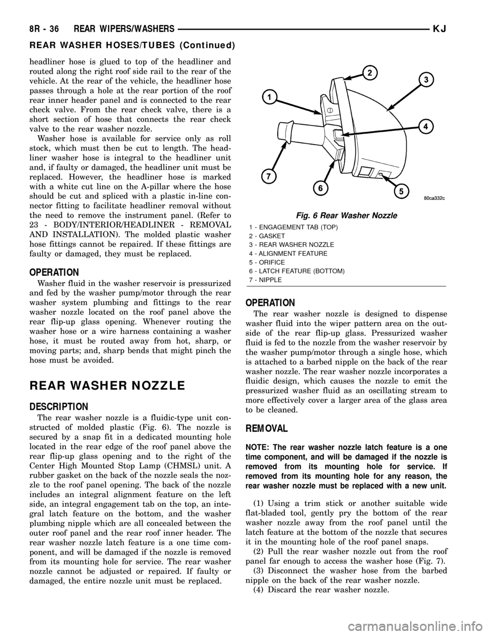
The rear washer nozzle is a fluidic-type unit con-
structed of molded plastic (Fig. 6). The nozzle is
secured by a snap fit in a dedicated mounting hole
located in the rear edge of the roof panel above the
rear flip-up glass opening and to the right of the
Center High Mounted Stop Lamp (CHMSL) unit. A
rubber gasket on the back of the nozzle seals the noz-
zle to the roof panel opening. The back of the nozzle
includes an integral alignment feature on the left
side, an integral engagement tab on the top, an inte-
gral latch feature on the bottom, and the washer
plumbing nipple which are all concealed between the
outer roof panel and the rear roof inner header. The
rear washer nozzle latch feature is a one time com-
ponent, and will be damaged if the nozzle is removed
from its mounting hole for service. The rear washer
nozzle cannot be adjusted or repaired. If faulty or
damaged, the entire nozzle unit must be replaced.
OPERATION
The rear washer nozzle is designed to dispense
washer fluid into the wiper pattern area on the out-
side of the rear flip-up glass. Pressurized washer
fluid is fed to the nozzle from the washer reservoir by
the washer pump/motor through a single hose, which
is attached to a barbed nipple on the back of the rear
washer nozzle. The rear washer nozzle incorporates a
fluidic design, which causes the nozzle to emit the
pressurized washer fluid as an oscillating stream to
more effectively cover a larger area of the glass area
to be cleaned.
REMOVAL
NOTE: The rear washer nozzle latch feature is a one
time component, and will be damaged if the nozzle is
removed from its mounting hole for service. If
removed from its mounting hole for any reason, the
rear washer nozzle must be replaced with a new unit.
(1) Using a trim stick or another suitable wide
flat-bladed tool, gently pry the bottom of the rear
washer nozzle away from the roof panel until the
latch feature at the bottom of the nozzle that secures
it in the mounting hole of the roof panel snaps.
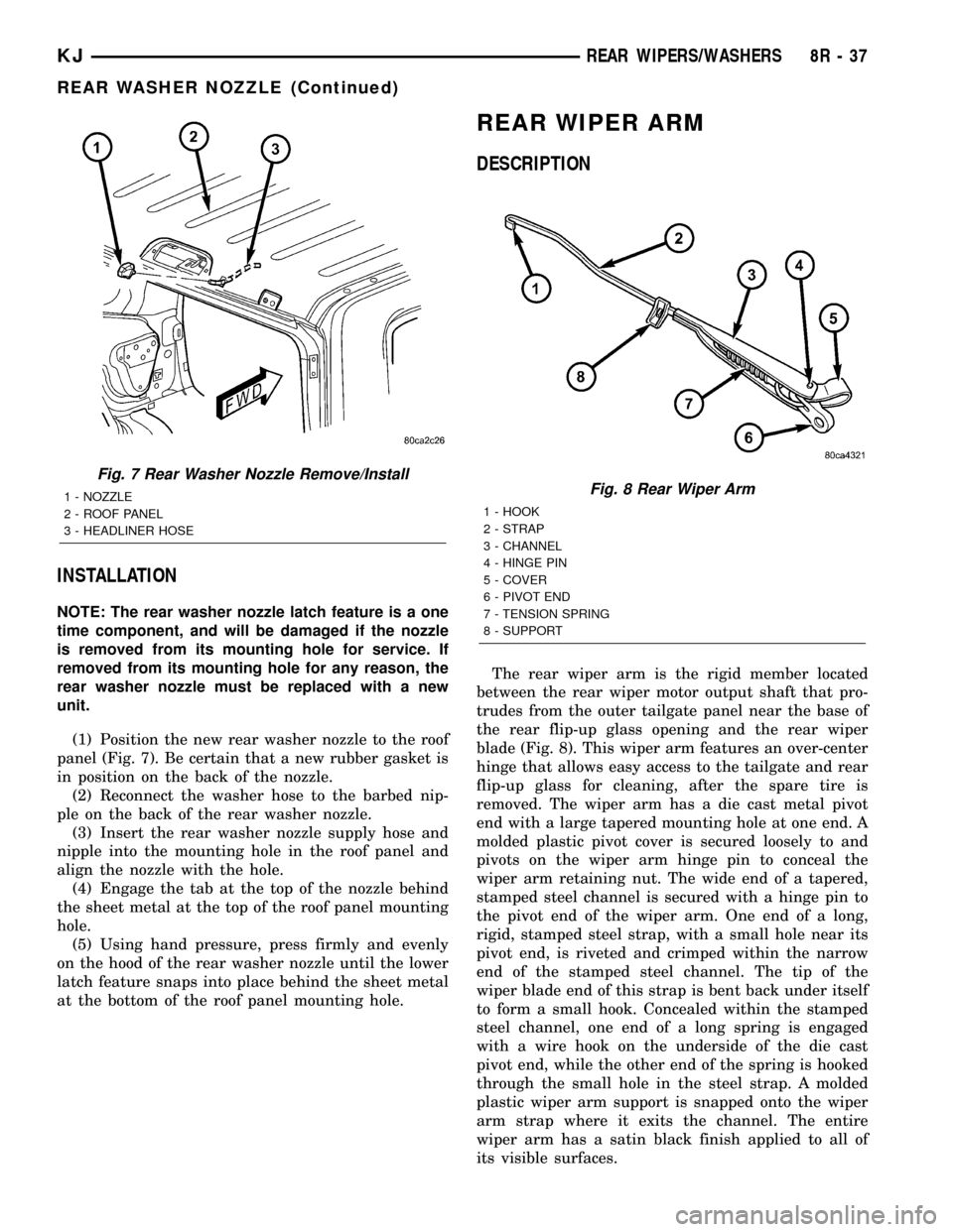
(2) Pull the rear washer nozzle out from the roof
panel far enough to access the washer hose (Fig. 7).
(3) Disconnect the washer hose from the barbed
nipple on the back of the rear washer nozzle.
(4) Discard the rear washer nozzle.
Fig. 6 Rear Washer Nozzle
1 - ENGAGEMENT TAB (TOP)
2 - GASKET
3 - REAR WASHER NOZZLE
4 - ALIGNMENT FEATURE
5 - ORIFICE
6 - LATCH FEATURE (BOTTOM)
7 - NIPPLE
8R - 36 REAR WIPERS/WASHERSKJ
REAR WASHER HOSES/TUBES (Continued)
Page 738 of 1803
INSTALLATION
NOTE: The rear washer nozzle latch feature is a one
time component, and will be damaged if the nozzle
is removed from its mounting hole for service. If
removed from its mounting hole for any reason, the
rear washer nozzle must be replaced with a new
unit.
(1) Position the new rear washer nozzle to the roof
panel (Fig. 7). Be certain that a new rubber gasket is
in position on the back of the nozzle.
(2) Reconnect the washer hose to the barbed nip-
ple on the back of the rear washer nozzle.
(3) Insert the rear washer nozzle supply hose and
nipple into the mounting hole in the roof panel and
align the nozzle with the hole.
(4) Engage the tab at the top of the nozzle behind
the sheet metal at the top of the roof panel mounting
hole.
(5) Using hand pressure, press firmly and evenly
on the hood of the rear washer nozzle until the lower
latch feature snaps into place behind the sheet metal
at the bottom of the roof panel mounting hole.
REAR WIPER ARM
DESCRIPTION
The rear wiper arm is the rigid member located
between the rear wiper motor output shaft that pro-
trudes from the outer tailgate panel near the base of
the rear flip-up glass opening and the rear wiper
blade (Fig. 8). This wiper arm features an over-center
hinge that allows easy access to the tailgate and rear
flip-up glass for cleaning, after the spare tire is
removed. The wiper arm has a die cast metal pivot
end with a large tapered mounting hole at one end. A
molded plastic pivot cover is secured loosely to and
pivots on the wiper arm hinge pin to conceal the
wiper arm retaining nut. The wide end of a tapered,
stamped steel channel is secured with a hinge pin to
the pivot end of the wiper arm. One end of a long,
rigid, stamped steel strap, with a small hole near its
pivot end, is riveted and crimped within the narrow
end of the stamped steel channel. The tip of the
wiper blade end of this strap is bent back under itself
to form a small hook. Concealed within the stamped
steel channel, one end of a long spring is engaged
with a wire hook on the underside of the die cast
pivot end, while the other end of the spring is hooked
through the small hole in the steel strap. A molded
plastic wiper arm support is snapped onto the wiper
arm strap where it exits the channel. The entire
wiper arm has a satin black finish applied to all of
its visible surfaces.
Fig. 7 Rear Washer Nozzle Remove/Install
1 - NOZZLE
2 - ROOF PANEL
3 - HEADLINER HOSEFig. 8 Rear Wiper Arm
1 - HOOK
2 - STRAP
3 - CHANNEL
4 - HINGE PIN
5 - COVER
6 - PIVOT END
7 - TENSION SPRING
8 - SUPPORT
KJREAR WIPERS/WASHERS 8R - 37
REAR WASHER NOZZLE (Continued)
Page 1219 of 1803
DIAGNOSIS AND TESTING
DIAGNOSIS AND TESTING - ENGINE
DIAGNOSIS - INTRODUCTION
Engine diagnosis is helpful in determining the
causes of malfunctions not detected and remedied by
routine maintenance.
These malfunctions may be classified as either per-
formance (e.g., engine idles rough and stalls) or
mechanical (e.g., a strange noise).
(Refer to 9 - ENGINE - DIAGNOSIS AND TEST-
ING)ÐPERFORMANCE and (Refer to 9 - ENGINE -
DIAGNOSIS AND TESTING)ÐMECHANICAL for
possible causes and corrections of malfunctions.
(Refer to 14 - FUEL SYSTEM/FUEL DELIVERY -
DIAGNOSIS AND TESTING) and (Refer to 14 -
FUEL SYSTEM/FUEL INJECTION - DIAGNOSIS
AND TESTING) for the fuel system diagnosis.Additional tests and diagnostic procedures may be
necessary for specific engine malfunctions that can
not be isolated with the Service Diagnosis charts.
Information concerning additional tests and diagno-
sis is provided within the following diagnosis:
²Cylinder Compression Pressure Test (Refer to 9 -
ENGINE - DIAGNOSIS AND TESTING).
²Cylinder Combustion Pressure Leakage Test
(Refer to 9 - ENGINE - DIAGNOSIS AND TEST-
ING).
²Engine Cylinder Head Gasket Failure Diagnosis
(Refer to 9 - ENGINE/CYLINDER HEAD - DIAGNO-
SIS AND TESTING).
²Intake Manifold Leakage Diagnosis (Refer to 9 -
ENGINE/MANIFOLDS/INTAKE MANIFOLD -
DIAGNOSIS AND TESTING).
DIAGNOSIS AND TESTING - ENGINE DIAGNOSIS - PERFORMANCE
CONDITION POSSIBLE CAUSE CORRECTION
ENGINE WILL NOT START 1. Weak battery 1. Charge or replace as necessary.
2. Corroded or loose battery
connections.2. Clean and tighten battery
connections. Apply a coat of light
mineral grease to the terminals.
3. Faulty starter. 3. (Refer to 8 - ELECTRICAL/
STARTING - DIAGNOSIS AND
TESTING).
4. Faulty coil or control unit. 4. (Refer to 8 - ELECTRICAL/
IGNITION CONTROL/IGNITION
COIL - REMOVAL).
5. Incorrect spark plug gap. 5. (Refer to 8 - ELECTRICAL/
IGNITION CONTROL/SPARK PLUG
- CLEANING).
6. Incorrect right bank cam timing. 6. Refer to engine timing in this
section.
7. Dirt or water in fuel system. 7. Clean system and replace fuel
filter.
8.Faulty fuel pump, relay or wiring. 8.Repair or replace as necessary.
9. Faulty cam or crank sensor 9. Refer to Ignition system.
ENGINE STALLS OR ROUGH IDLE 1. Vacuum leak. 1. Inspect intake manifold and
vacuum hoses, repair or replace as
necessary.
2. Faulty crank position sensor 2. Replace crank position sensor.
4. Faulty coil. 4. (Refer to 8 - ELECTRICAL/
IGNITION CONTROL/IGNITION
COIL - REMOVAL).
9 - 4 ENGINE - 3.7LKJ
ENGINE - 3.7L (Continued)
Page 1220 of 1803
CONDITION POSSIBLE CAUSE CORRECTION
5. Incorrect cam timing. 5. (Refer to 9 - ENGINE/VALVE
TIMING - STANDARD
PROCEDURE).
1. ENGINE LOSS OF POWER 1. Dirty or incorrectly gapped spark
plugs.1. (Refer to 8 - ELECTRICAL/
IGNITION CONTROL/SPARK PLUG
- CLEANING).
2. Dirt or water in fuel system. 2. Clean system and replace fuel
filter.
3. Faulty fuel pump. 3. (Refer to 14 - FUEL SYSTEM/
FUEL DELIVERY/FUEL PUMP -
DIAGNOSIS AND TESTING).
4. Blown cylinder head gasket. 4. Replace cylinder head gasket.
5. Low compression. 5. (Refer to 9 - ENGINE -
DIAGNOSIS AND TESTING), repair
as necessary.
6. Burned, warped or pitted valves. 6. Replace as necessary.
7. Plugged or restricted exhaust
system.7. Inspect and replace as
necessary.
8. Faulty coil. 8. (Refer to 8 - ELECTRICAL/
IGNITION CONTROL/IGNITION
COIL - REMOVAL).
9. Incorrect cam timing. 9. Refer to Engine TIming in this
section.
1. ENGINE MISSES ON
ACCELERATION1. Spark plugs dirty or incorrectly
gapped.1. (Refer to 8 - ELECTRICAL/
IGNITION CONTROL/SPARK PLUG
- CLEANING).
2. Dirt in fuel system. 2. Clean fuel system.
3. Burned, warped or pitted valves. 3. Replcae as necessary.
4. Faulty coil. 4. (Refer to 8 - ELECTRICAL/
IGNITION CONTROL/IGNITION
COIL - REMOVAL).
1. ENGINE MISSES AT HIGH
SPEED1. Spark plugs dirty or incorrectly
gapped.1. (Refer to 8 - ELECTRICAL/
IGNITION CONTROL/SPARK PLUG
- CLEANING).
2. Faulty coil. 2. (Refer to 8 - ELECTRICAL/
IGNITION CONTROL/IGNITION
COIL - REMOVAL).
3. Dirt or water in fuel system. 3. Clean system and replace fuel
filter.
KJENGINE - 3.7L 9 - 5
ENGINE - 3.7L (Continued)
Page 1224 of 1803
CYLINDER COMBUSTION PRESSURE LEAKAGE DIAGNOSIS CHART
CONDITION POSSIBLE CAUSE CORRECTION
AIR ESCAPES THROUGH
THROTTLE BODYIntake valve bent, burnt, or not
seated properlyInspect valve and valve seat.
Reface or replace, as necessary.
Inspect valve springs. Replace as
necessary.
AIR ESCAPES THROUGH
TAILPIPEExhaust valve bent, burnt, or not
seated properlyInspect valve and valve seat.
Reface or replace, as necessary.
Inspect valve springs. Replace as
necessary.
AIR ESCAPES THROUGH
RADIATORHead gasket leaking or cracked
cylinder head or blockRemove cylinder head and inspect.
Replace defective part
MORE THAN 50% LEAKAGE
FROM ADJACENT CYLINDERSHead gasket leaking or crack in
cylinder head or block between
adjacent cylindersRemove cylinder head and inspect.
Replace gasket, head, or block as
necessary
MORE THAN 25% LEAKAGE AND
AIR ESCAPES THROUGH OIL
FILLER CAP OPENING ONLYStuck or broken piston rings;
cracked piston; worn rings and/or
cylinder wallInspect for broken rings or piston.
Measure ring gap and cylinder
diameter, taper and out-of-round.
Replace defective part as necessary
STANDARD PROCEDURE
STANDARD PROCEDURE - ENGINE GASKET
SURFACE PREPARATION
To ensure engine gasket sealing, proper surface
preparation must be performed, especially with the
use of aluminum engine components and multi-layer
steel cylinder head gaskets.
Neveruse the following to clean gasket surfaces:
²Metal scraper
²Abrasive pad or paper to clean cylinder block
and head
²High speed power tool with an abrasive pad or a
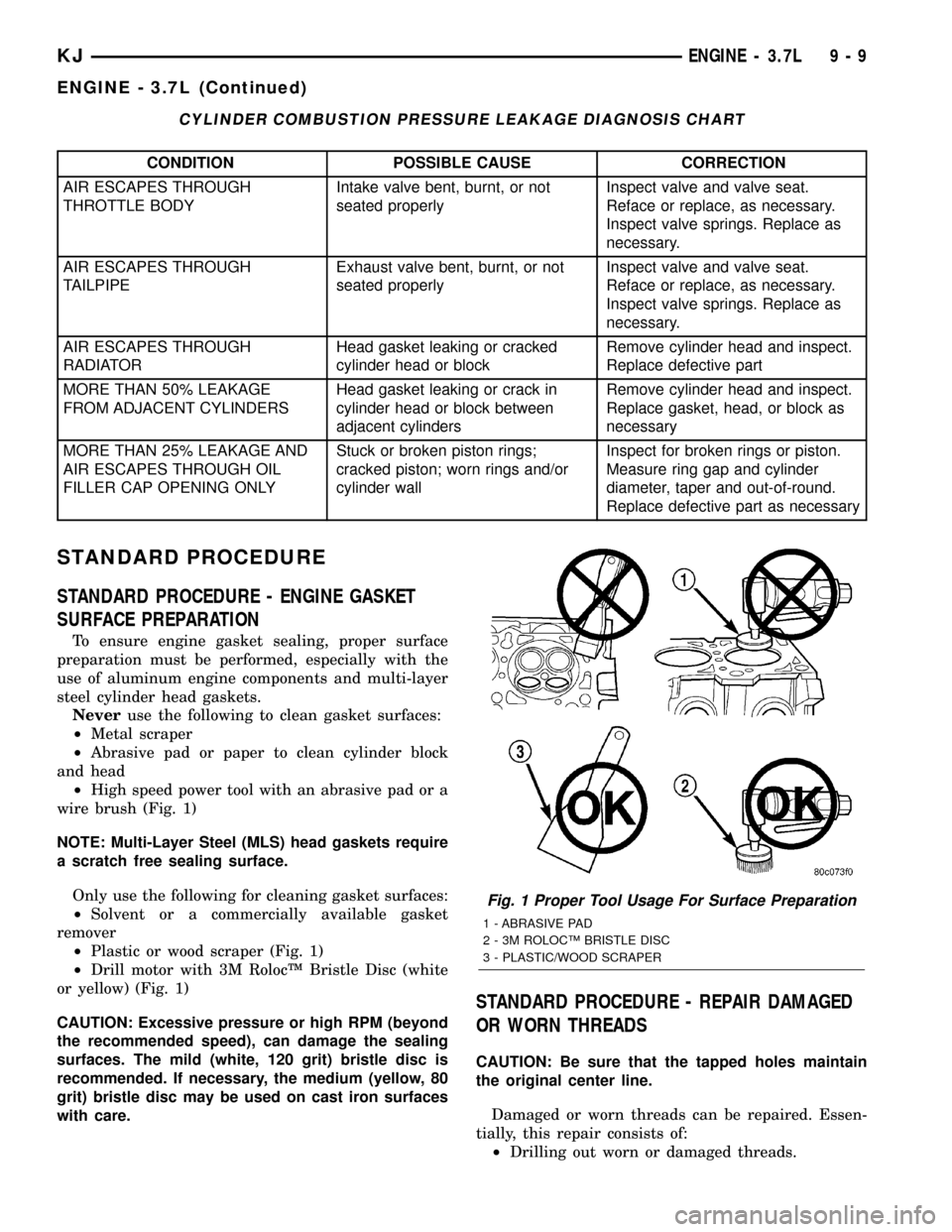
wire brush (Fig. 1)
NOTE: Multi-Layer Steel (MLS) head gaskets require
a scratch free sealing surface.
Only use the following for cleaning gasket surfaces:
²Solvent or a commercially available gasket
remover
²Plastic or wood scraper (Fig. 1)
²Drill motor with 3M RolocŸ Bristle Disc (white
or yellow) (Fig. 1)
CAUTION: Excessive pressure or high RPM (beyond
the recommended speed), can damage the sealing
surfaces. The mild (white, 120 grit) bristle disc is
recommended. If necessary, the medium (yellow, 80
grit) bristle disc may be used on cast iron surfaces
with care.
STANDARD PROCEDURE - REPAIR DAMAGED
OR WORN THREADS
CAUTION: Be sure that the tapped holes maintain
the original center line.
Damaged or worn threads can be repaired. Essen-
tially, this repair consists of:
²Drilling out worn or damaged threads.
Fig. 1 Proper Tool Usage For Surface Preparation
1 - ABRASIVE PAD
2 - 3M ROLOCŸ BRISTLE DISC
3 - PLASTIC/WOOD SCRAPER
KJENGINE - 3.7L 9 - 9
ENGINE - 3.7L (Continued)
Page 1234 of 1803
AIR CLEANER ELEMENT
REMOVAL - 3.7L
Housing removal is not necessary for element (fil-
ter) replacement.
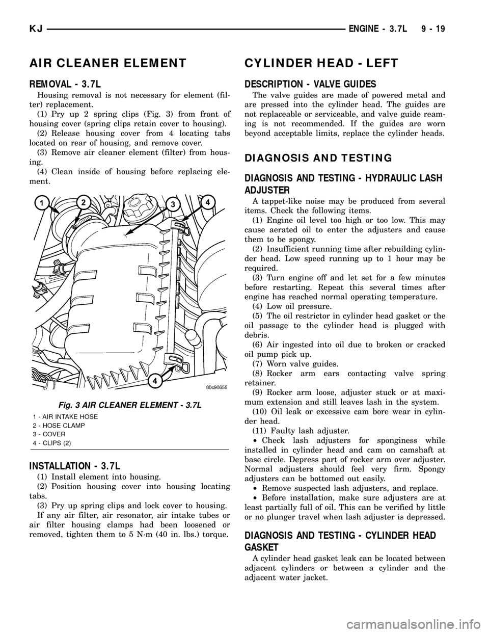
(1) Pry up 2 spring clips (Fig. 3) from front of
housing cover (spring clips retain cover to housing).
(2) Release housing cover from 4 locating tabs
located on rear of housing, and remove cover.
(3) Remove air cleaner element (filter) from hous-
ing.
(4) Clean inside of housing before replacing ele-
ment.
INSTALLATION - 3.7L
(1) Install element into housing.
(2) Position housing cover into housing locating
tabs.
(3) Pry up spring clips and lock cover to housing.
If any air filter, air resonator, air intake tubes or
air filter housing clamps had been loosened or
removed, tighten them to 5 N´m (40 in. lbs.) torque.
CYLINDER HEAD - LEFT
DESCRIPTION - VALVE GUIDES
The valve guides are made of powered metal and
are pressed into the cylinder head. The guides are
not replaceable or serviceable, and valve guide ream-
ing is not recommended. If the guides are worn
beyond acceptable limits, replace the cylinder heads.
DIAGNOSIS AND TESTING
DIAGNOSIS AND TESTING - HYDRAULIC LASH
ADJUSTER
A tappet-like noise may be produced from several
items. Check the following items.
(1) Engine oil level too high or too low. This may
cause aerated oil to enter the adjusters and cause
them to be spongy.
(2) Insufficient running time after rebuilding cylin-
der head. Low speed running up to 1 hour may be
required.
(3) Turn engine off and let set for a few minutes
before restarting. Repeat this several times after
engine has reached normal operating temperature.
(4) Low oil pressure.
(5) The oil restrictor in cylinder head gasket or the
oil passage to the cylinder head is plugged with
debris.
(6) Air ingested into oil due to broken or cracked
oil pump pick up.
(7) Worn valve guides.
(8) Rocker arm ears contacting valve spring
retainer.
(9) Rocker arm loose, adjuster stuck or at maxi-
mum extension and still leaves lash in the system.
(10) Oil leak or excessive cam bore wear in cylin-
der head.
(11) Faulty lash adjuster.
²Check lash adjusters for sponginess while
installed in cylinder head and cam on camshaft at
base circle. Depress part of rocker arm over adjuster.
Normal adjusters should feel very firm. Spongy
adjusters can be bottomed out easily.
²Remove suspected lash adjusters, and replace.
²Before installation, make sure adjusters are at
least partially full of oil. This can be verified by little
or no plunger travel when lash adjuster is depressed.
DIAGNOSIS AND TESTING - CYLINDER HEAD
GASKET
A cylinder head gasket leak can be located between
adjacent cylinders or between a cylinder and the
adjacent water jacket.
Fig. 3 AIR CLEANER ELEMENT - 3.7L
1 - AIR INTAKE HOSE
2 - HOSE CLAMP
3 - COVER
4 - CLIPS (2)
KJENGINE - 3.7L 9 - 19