battery JEEP LIBERTY 2004 KJ / 1.G User Guide
[x] Cancel search | Manufacturer: JEEP, Model Year: 2004, Model line: LIBERTY, Model: JEEP LIBERTY 2004 KJ / 1.GPages: 374, PDF Size: 5.71 MB
Page 205 of 374
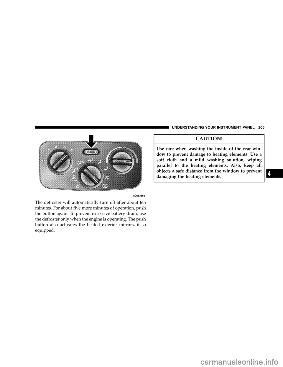
The defroster will automatically turn off after about ten
minutes. For about five more minutes of operation, push
the button again. To prevent excessive battery drain, use
the defroster only when the engine is operating. The push
button also activates the heated exterior mirrors, if so
equipped.
CAUTION!
Use care when washing the inside of the rear win-
dow to prevent damage to heating elements. Use a
soft cloth and a mild washing solution, wiping
parallel to the heating elements. Also, keep all
objects a safe distance from the window to prevent
damaging the heating elements.
UNDERSTANDING YOUR INSTRUMENT PANEL 205
4
Page 272 of 374
HAZARD WARNING FLASHERS
Your vehicle's hazard warning flasher is an emergency
warning system. When you activate it, all front and rear
directional signals will flash intermittently. Use it when
your vehicle is disabled on or near the road. It warns
other drivers to steer clear of you and your vehicle. This
is an emergency warning system, not to be used when the
vehicle is in motion.
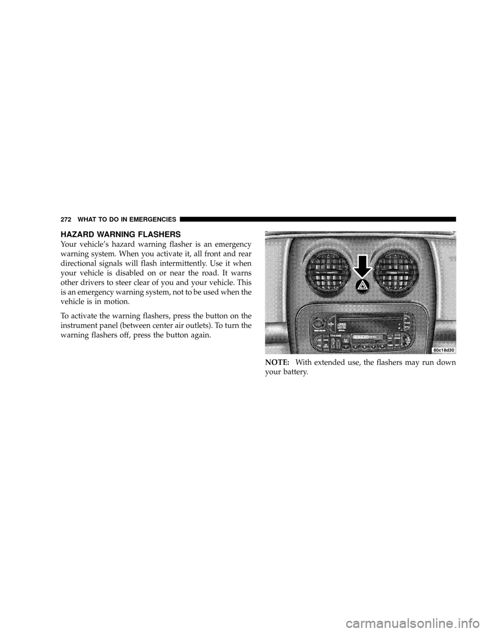
To activate the warning flashers, press the button on the
instrument panel (between center air outlets). To turn the
warning flashers off, press the button again.
NOTE:With extended use, the flashers may run down
your battery.
272 WHAT TO DO IN EMERGENCIES
Page 279 of 374
²Do not let passengers sit in the vehicle when it is on a
jack.
²Do not get under the vehicle when it is on a jack.
²Failure to follow the ªTire Changing Procedureº may
result in personal injury or damage to your vehicle.
²Only use the jack in the positions indicated.
JUMP STARTING PROCEDURE
NOTE:Check the charge indicator on the battery. If the
indicator is light or yellow, replace the battery.
1. Wear eye protection and remove any metal jewelry
such as watch bands or bracelets that might make an
unintended electrical contact.
2. When boost is provided by a battery in another
vehicle, park that vehicle within booster cable reach but
without letting the vehicles touch. Set the parking brake,place the automatic transmission in P (Park), or manual
transmission in N (Neutral), and turn the ignition to OFF
for both vehicles.
3. Turn off the heater, radio and all unnecessary electrical
loads.
4. Connect one end of a jumper cable to the positive
terminal of the discharged battery. Connect the other end
of the same cable to the positive terminal of the booster
battery.
5. Connect the other cable, first to the negative terminal
of the booster battery and then connect the other end to
a non-paint metal surface on the engine of the vehicle
with the discharged battery. Make sure you have a good
contact on the engine.
6. Start the engine in the vehicle which has the booster
battery, let the engine idle a few minutes, then start the
engine in the vehicle with the discharged battery.
WHAT TO DO IN EMERGENCIES 279
6
Page 280 of 374
7. When removing the jumper cables, reverse the above
sequence exactly. Be careful of the moving belts and fan.
NOTE:To start the vehicle following connection of a
booster battery, the Security Alarm System must first be
disabled by cycling a front door key cylinder or by using
the keyless entry transmitter.
WARNING!
Jump starting can be dangerous. To avoid personal
injury or damage to electrical components in vehicle,
observe the following warnings:
²Battery fluid is a corrosive acid solution and can burn
or even blind you. Don't allow battery fluid to contact
your eyes, skin, or clothing. Don't lean over a batterywhen attaching clamps. If acid splashes in eyes or on
skin, flush the area immediately with large amounts of
water.
²Do not use a booster battery or any other booster
source that has a greater than 12±volt system, i.e., do
not use a 24±volt power source.
²Never attempt to jump start a discharged battery that
is frozen, because it could rupture or explode during
jump starting.
²Be sure your vehicle is not touching the jump start
vehicle.
²Observe all Battery Warnings in Section 7 of this
manual, while jump starting your vehicle.
280 WHAT TO DO IN EMERGENCIES
Page 283 of 374
MAINTAINING YOUR VEHICLE
CONTENTS
m2.4L Engine...........................285
m3.7L Engine...........................286
mOnboard Diagnostic System Ð OBD II........287
mEmissions Inspection And Maintenance
Programs............................288
mReplacement Parts......................289
mDealer Service.........................289
mMaintenance Procedures..................290
NEngine Oil..........................290NDrive Belts Ð Check Condition And Tension . . 294
NSpark Plugs.........................295
NCatalytic Converter....................295
NEngine Timing Belt Ð 2.4L Engine.........297
NIgnition Wiring System Ð 2.4L Engine......297
NCrankcase Emission Control System........297
NAir Cleaner Filter.....................297
NMaintenance-Free Battery................298
NAir Conditioner Maintenance.............299
7
Page 288 of 374
EMISSIONS INSPECTION AND MAINTENANCE
PROGRAMS
In some localities, it may be a legal requirement to pass
an inspection of your vehicle's emissions control system.
Failure to pass could prevent vehicle registration.
For states which have an I/M (Inspection and
Maintenance) requirement, this check verifies the
following: the MIL (Malfunction Indicator Lamp)
is functioning and is not on when the engine is running,
and that the OBD (On Board Diagnostic) system is ready
for testing.
Normally, the OBD system will be ready. The OBD
system maynotbe ready if your vehicle was recently
serviced, if you recently had a dead battery, or a battery
replacement. If the OBD system should be determined
not ready for the I/M test, your vehicle may fail the test.Your vehicle has a simple ignition key actuated test
which you can use prior to going to the test station. To
check if your vehicle's OBD system is ready, you must do
the following:
1. Insert your ignition key into the ignition switch.
2. Turn the ignition to the ON position, but do not crank
or start the engine.
3. If you crank or start the engine, you will have to start
this test over.
4. As soon as you turn your key to the ON position, you
will see your MIL symbol come on as part of a normal
bulb check.
5. Approximately 15 seconds later, one of two things will
happen:
a. The MIL will flash for about 10 seconds and then
return to being fully illuminated until you turn off the
288 MAINTAINING YOUR VEHICLE
Page 289 of 374
ignition key or start the engine. This means that your
vehicle's OBD system isnot readyand you shouldnot
proceed to the I/M station.
b. The MIL will not flash at all and will remain fully
illuminated until you turn off the ignition key or start
the engine. This means that your vehicle's OBD system
isreadyand you can proceed to the I/M station.
If your OBD system isnot ready,you should see your
authorized dealer or repair facility. If your vehicle was
recently serviced or had a battery failure or replacement,
you may need to do nothing more than drive your
vehicle as you normally would in order for your OBD
system to update. A recheck with the above test routine
may then indicate that the system is now ready.
Regardless of whether your vehicle's OBD system is
ready or not ready, if the MIL symbol is illuminated
during normal vehicle operation, you should have yourvehicle serviced before going to the I/M station. The I/M
station can fail your vehicle because the MIL symbol is on
with the engine running.
REPLACEMENT PARTS
Use of genuine Mopartparts for normal/scheduled
maintenance and repairs is highly recommended to in-
sure the designed performance. Damage or failures
caused by the use of non-Mopartparts for maintenance
and repairs will not be covered by the manufacturer's
warranty.
DEALER SERVICE
Your dealer has the qualified service personnel, special
tools and equipment to perform all service operations in
an expert manner. Service Manuals are available which
include detailed service information for your vehicle.
Refer to these manuals before attempting any procedure
yourself.
MAINTAINING YOUR VEHICLE 289
7
Page 298 of 374
Maintenance-Free Battery
Your vehicle is equipped with a maintenance-free battery.
You will never have to add water, nor is periodic main-
tenance required.
WARNING!
Battery posts, terminals, and related accessories con-
tain lead and lead compounds. Always wash hands
after handling the battery.
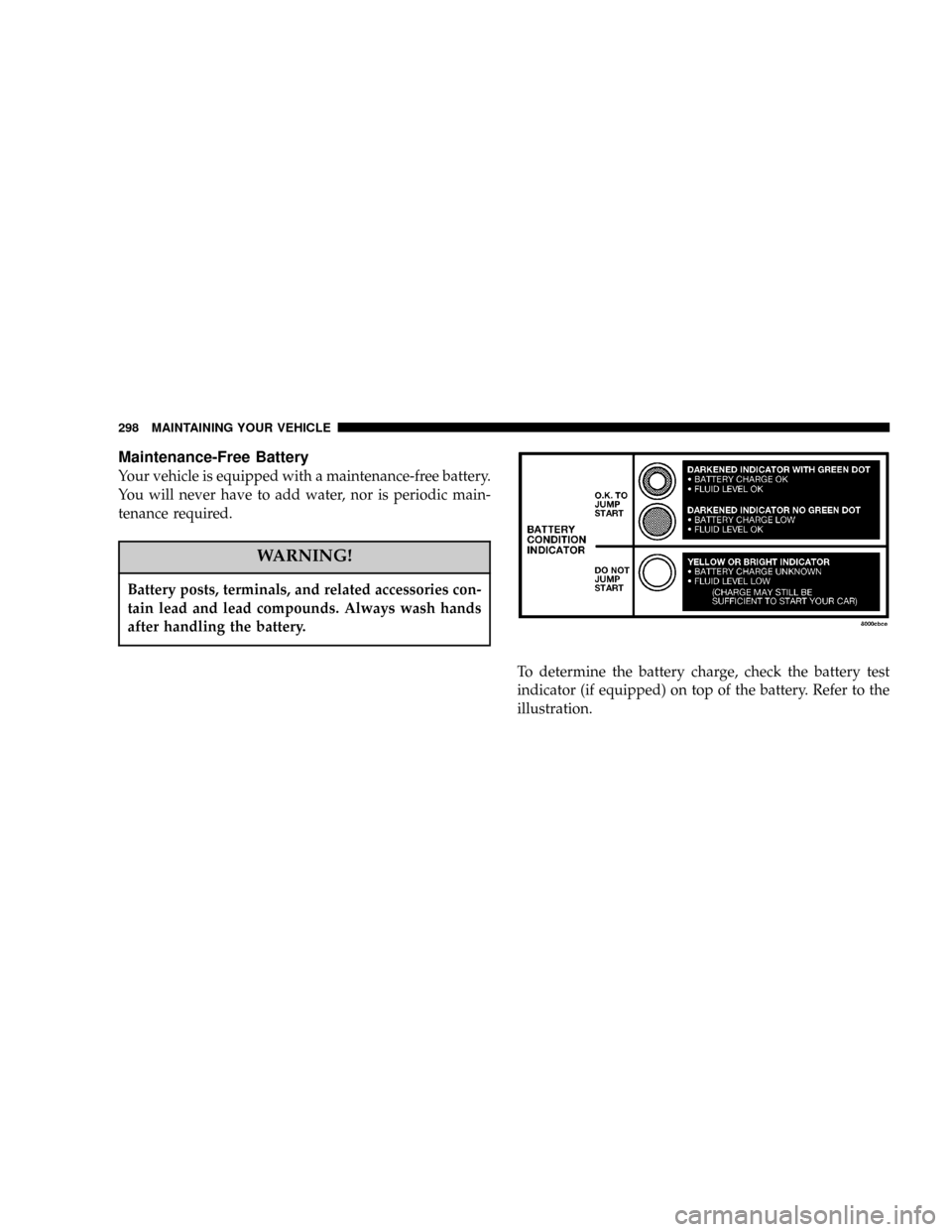
To determine the battery charge, check the battery test
indicator (if equipped) on top of the battery. Refer to the
illustration.
298 MAINTAINING YOUR VEHICLE
Page 299 of 374
CAUTION!
It is essential when replacing the cables on the
battery that the positive cable is attached to the
positive post and the negative cable is attached to the
negative post. Battery posts are marked (+) positive
and negative (-) and identified on the battery case.
Also, if a ªfast chargerº is used while battery is in the
vehicle, disconnect both vehicle battery cables be-
fore connecting the charger to battery. Do not use a
ªfast chargerº to provide starting voltage.
Air Conditioner Maintenance
For best possible performance, your air conditioner
should be checked and serviced by an Authorized Dealer
at the start of each warm season. This service should
include cleaning of the condenser fins and a performance
test. Drive belt tension should also be checked at this
time.
WARNING!
²Use only refrigerants and compressor lubricants
approved by the manufacturer for your air condi-
tioning system. Some unapproved refrigerants are
flammable and can explode, injuring you. Other
unapproved refrigerants or lubricants can cause
the system to fail, requiring costly repairs.
²The air conditioning system contains refrigerant
under high pressure. To avoid risk of personal
injury or damage to the system, adding refrigerant
or any repair requiring lines to be disconnected
should be done by an experienced repairman.
MAINTAINING YOUR VEHICLE 299
7
Page 322 of 374

Cavity Fuse Description
18 20 Amp Yel-
lowRadio Choke & Relay
19 20 Amp Yel-
lowFrt Fog Lights/Trailer Tow
Stop and Turn Lights
20 Spare
21 10 Amp Red Radio
22 20 Amp Yel-
lowPower Sunroof Relay/
Antenna Module (Export
Only)
23 Spare
24 10 Amp Red PDC Blower Motor
25 10 Amp Red Heated Seat Switches/HVAC
Control Head/Trailer Tow
Battery Charge
26 10 Amp Red Headlight High Beam Right
27 10 Amp Red Headlight High Beam Left
28 SpareCavity Fuse Description
29 10 Amp Red Heated Mirrors/Rear Win-
dow Defroster Indicator
30 15 Amp Blue Heated Seat Module
31 Spare
32 10 Amp Red Wiper Switch/Front and
Rear Wipers
33 10 Amp Red SKIM Module/Data Link
Connector
34 15 Amp Blue Body Control Module/
Cluster/Interior Lights,
Hands Free Module/Radio/
CMTC/ITM Module & Siren
(Export Only)
35 Spare
36 10 Amp Red Airbag Control Module/
Occupation Classification
Module (Right Front Seat)
322 MAINTAINING YOUR VEHICLE