fuel JEEP LIBERTY 2010 KK / 2.G User Guide
[x] Cancel search | Manufacturer: JEEP, Model Year: 2010, Model line: LIBERTY, Model: JEEP LIBERTY 2010 KK / 2.GPages: 80
Page 8 of 80
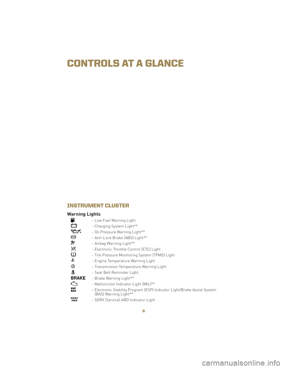
INSTRUMENT CLUSTER
Warning Lights
- Low Fuel Warning Light
- Charging System Light**
- Oil Pressure Warning Light**
- Anti-Lock Brake (ABS) Light**
- Airbag Warning Light**
- Electronic Throttle Control (ETC) Light
- Tire Pressure Monitoring System (TPMS) Light
- Engine Temperature Warning Light
- Transmission Temperature Warning Light
- Seat Belt Reminder Light
BRAKE- Brake Warning Light**
- Malfunction Indicator Light (MIL)**
- Electronic Stability Program (ESP) Indicator Light/Brake Assist System(BAS) Warning Light**
- SERV (Service) 4WD Indicator Light
6
CONTROLS AT A GLANCE
Page 9 of 80
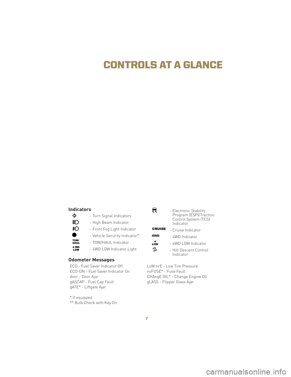
Indicators
- Turn Signal Indicators
- High Beam Indicator
- Front Fog Light Indicator
- Vehicle Security Indicator*
- TOW/HAUL Indicator
- 4WD LOW Indicator Light
- Electronic StabilityProgram (ESP)/Traction
Control System (TCS)
Indicator
- Cruise Indicator
- 4WD Indicator
- 4WD LOW Indicator
- Hill Descent ControlIndicator
Odometer Messages
ECO - Fuel Saver Indicator Off LoW tirE - Low Tire Pressure
ECO-ON - Fuel Saver Indicator On noFUSE* - Fuse Fault
door - Door Ajar CHAngE OIL* - Change Engine Oil
gASCAP - Fuel Cap Fault gLASS - Flipper Glass Ajar
gATE* - Liftgate Ajar
* If equipped
** Bulb Check with Key On
7
CONTROLS AT A GLANCE
Page 34 of 80
Guide Me Home
• Press the NAV hard-key to access the Navigation Main Menu.
• Touch the GUIDE ME HOME soft-key to route you back to your home destination fromyour current location. Touch the GO soft-key to start your trip.
Map
• Press the NAV hard-key to access the Navigation Main Menu.
• Touch the MAP soft-key to display a map of your current position.
REMOTE AUDIO CONTROLS
• The remote audio controls are located on therear surface of the steering wheel.
Right Switch
• Press the switch up or down to increase ordecrease the volume.
• Press the button in the center to change modes AM/FM/CD/SAT.
Left Switch
• Press the switch up or down to search for thenext listenable station or select the next or
previous CD track.
• Press the button in the center to select the next preset station (radio) or to change CDs if equipped with a CD Changer.
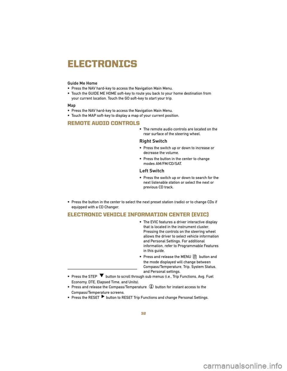
ELECTRONIC VEHICLE INFORMATION CENTER (EVIC)
• The EVIC features a driver interactive displaythat is located in the instrument cluster.
Pressing the controls on the steering wheel
allows the driver to select vehicle information
and Personal Settings. For additional
information, refer to Programmable Features
in this guide.
• Press and release the MENU
button and
the mode displayed will change between
Compass/Temperature, Trip, System Status,
and Personal settings.
• Press the STEP
button to scroll through sub menus (i.e., Trip Functions, Avg. Fuel
Economy, DTE, Elapsed Time, and Units).
• Press and release the Compass/Temperature
button for instant access to the
Compass/Temperature screens.
• Press the RESET
button to RESET Trip Functions and change Personal Settings.
ELECTRONICS
32
Page 46 of 80
24-HOUR TOWING ASSISTANCE - U.S. ONLY
• Dial toll-free 1-800-521-2779 or 1-800-363-4869 for Canadian residents.
• Provide your name, vehicle identification number and license plate number.
• Provide your location, including telephone number, from which you are calling.
• Briefly describe the nature of the problem and answer a few simple questions.
• You will be given the name of the service provider and an estimated time of arrival. If youfeel you are in an “unsafe situation”, please let us know. With your consent, we will
contact local police or safety authorities.
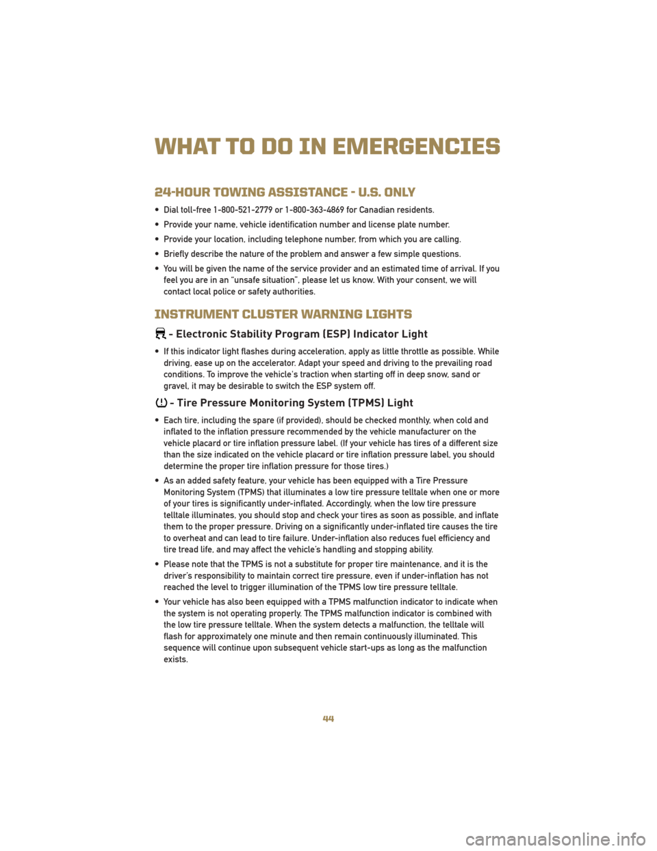
INSTRUMENT CLUSTER WARNING LIGHTS
- Electronic Stability Program (ESP) Indicator Light
• If this indicator light flashes during acceleration, apply as little throttle as possible. Whiledriving, ease up on the accelerator. Adapt your speed and driving to the prevailing road
conditions. To improve the vehicle's traction when starting off in deep snow, sand or
gravel, it may be desirable to switch the ESP system off.
- Tire Pressure Monitoring System (TPMS) Light
• Each tire, including the spare (if provided), should be checked monthly, when cold andinflated to the inflation pressure recommended by the vehicle manufacturer on the
vehicle placard or tire inflation pressure label. (If your vehicle has tires of a different size
than the size indicated on the vehicle placard or tire inflation pressure label, you should
determine the proper tire inflation pressure for those tires.)
• As an added safety feature, your vehicle has been equipped with a Tire Pressure Monitoring System (TPMS) that illuminates a low tire pressure telltale when one or more
of your tires is significantly under-inflated. Accordingly, when the low tire pressure
telltale illuminates, you should stop and check your tires as soon as possible, and inflate
them to the proper pressure. Driving on a significantly under-inflated tire causes the tire
to overheat and can lead to tire failure. Under-inflation also reduces fuel efficiency and
tire tread life, and may affect the vehicle’s handling and stopping ability.
• Please note that the TPMS is not a substitute for proper tire maintenance, and it is the driver’s responsibility to maintain correct tire pressure, even if under-inflation has not
reached the level to trigger illumination of the TPMS low tire pressure telltale.
• Your vehicle has also been equipped with a TPMS malfunction indicator to indicate when the system is not operating properly. The TPMS malfunction indicator is combined with
the low tire pressure telltale. When the system detects a malfunction, the telltale will
flash for approximately one minute and then remain continuously illuminated. This
sequence will continue upon subsequent vehicle start-ups as long as the malfunction
exists.
WHAT TO DO IN EMERGENCIES
44
Page 48 of 80
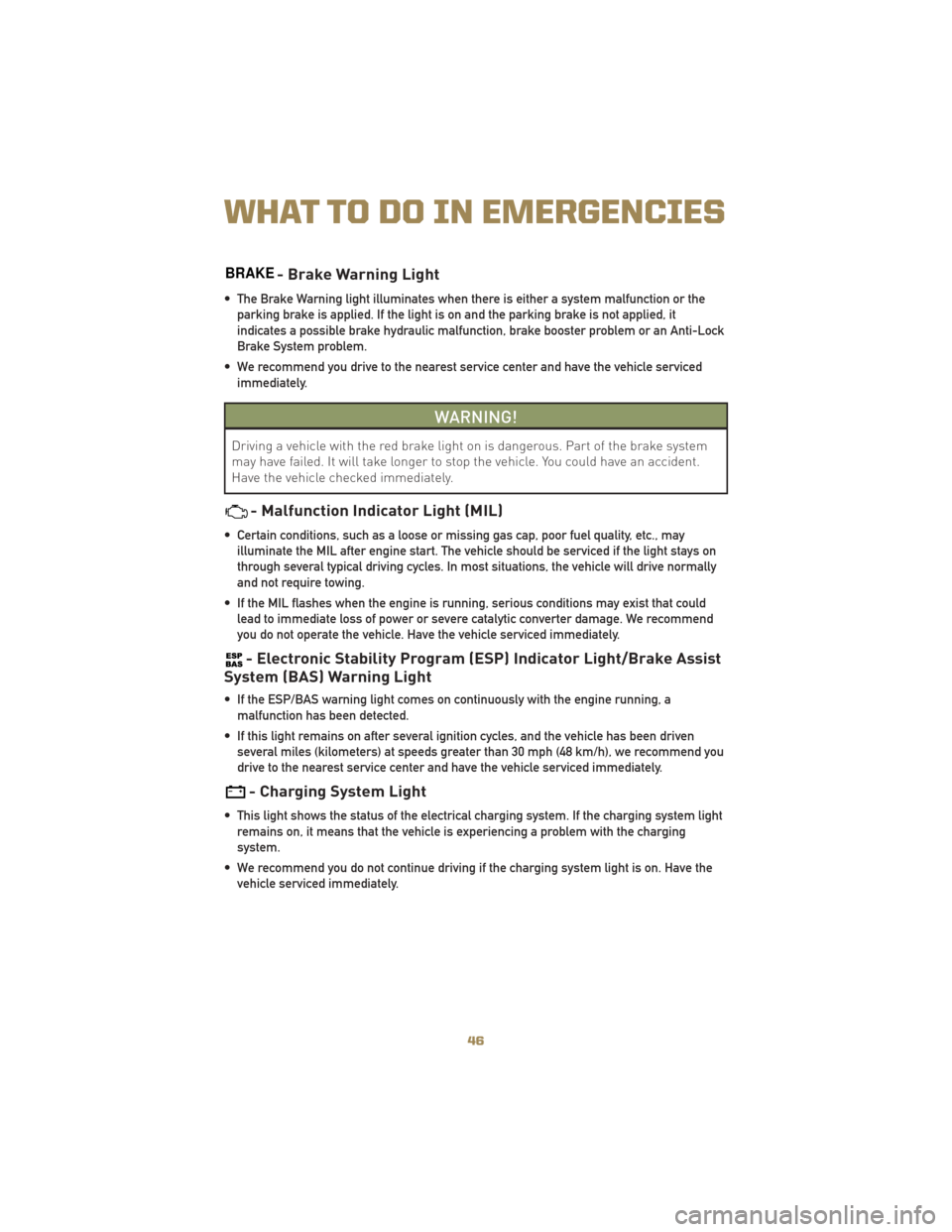
BRAKE- Brake Warning Light
• The Brake Warning light illuminates when there is either a system malfunction or theparking brake is applied. If the light is on and the parking brake is not applied, it
indicates a possible brake hydraulic malfunction, brake booster problem or an Anti-Lock
Brake System problem.
• We recommend you drive to the nearest service center and have the vehicle serviced immediately.
WARNING!
Driving a vehicle with the red brake light on is dangerous. Part of the brake system
may have failed. It will take longer to stop the vehicle. You could have an accident.
Have the vehicle checked immediately.
- Malfunction Indicator Light (MIL)
• Certain conditions, such as a loose or missing gas cap, poor fuel quality, etc., mayilluminate the MIL after engine start. The vehicle should be serviced if the light stays on
through several typical driving cycles. In most situations, the vehicle will drive normally
and not require towing.
• If the MIL flashes when the engine is running, serious conditions may exist that could lead to immediate loss of power or severe catalytic converter damage. We recommend
you do not operate the vehicle. Have the vehicle serviced immediately.
- Electronic Stability Program (ESP) Indicator Light/Brake Assist
System (BAS) Warning Light
• If the ESP/BAS warning light comes on continuously with the engine running, a
malfunction has been detected.
• If this light remains on after several ignition cycles, and the vehicle has been driven several miles (kilometers) at speeds greater than 30 mph (48 km/h), we recommend you
drive to the nearest service center and have the vehicle serviced immediately.
- Charging System Light
• This light shows the status of the electrical charging system. If the charging system lightremains on, it means that the vehicle is experiencing a problem with the charging
system.
• We recommend you do not continue driving if the charging system light is on. Have the vehicle serviced immediately.
WHAT TO DO IN EMERGENCIES
46
Page 50 of 80
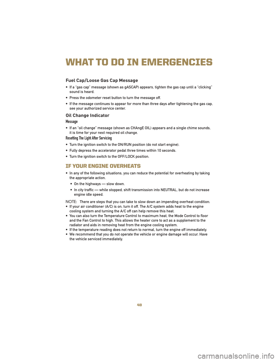
Fuel Cap/Loose Gas Cap Message
• If a “gas cap” message (shown as gASCAP) appears, tighten the gas cap until a “clicking”sound is heard.
• Press the odometer reset button to turn the message off.
• If the message continues to appear for more than three days after tightening the gas cap, see your authorized service center.
Oil Change Indicator
Message
• If an “oil change” message (shown as CHAngE OIL) appears and a single chime sounds,it is time for your next required oil change.
Resetting The Light After Servicing
• Turn the ignition switch to the ON/RUN position (do not start engine).
• Fully depress the accelerator pedal three times within 10 seconds.
• Turn the ignition switch to the OFF/LOCK position.
IF YOUR ENGINE OVERHEATS
• In any of the following situations, you can reduce the potential for overheating by takingthe appropriate action.
• On the highways — slow down.
• In city traffic — while stopped, shift transmission into NEUTRAL, but do not increase engine idle speed.
NOTE: There are steps that you can take to slow down an impending overheat condition:
• If your air conditioner (A/C) is on, turn it off. The A/C system adds heat to the engine cooling system and turning the A/C off can help remove this heat.
• You can also turn the Temperature Control to maximum heat, the Mode Control to floor and the Fan Control to high. This allows the heater core to act as a supplement to the
radiator and aids in removing heat from the engine cooling system.
• If the temperature reading does not return to normal, turn the engine off immediately.
• We recommend that you do not operate the vehicle or engine damage will occur. Have the vehicle serviced immediately.
WHAT TO DO IN EMERGENCIES
48
Page 57 of 80
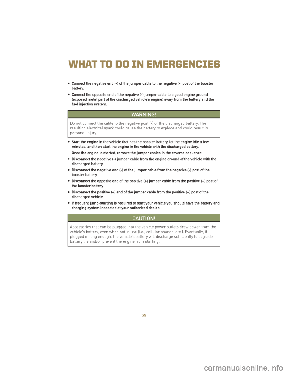
• Connect the negative end (-) of the jumper cable to the negative (-) post of the boosterbattery.
• Connect the opposite end of the negative (-) jumper cable to a good engine ground (exposed metal part of the discharged vehicle’s engine) away from the battery and the
fuel injection system.
WARNING!
Do not connect the cable to the negative post (-) of the discharged battery. The
resulting electrical spark could cause the battery to explode and could result in
personal injury.
• Start the engine in the vehicle that has the booster battery, let the engine idle a few minutes, and then start the engine in the vehicle with the discharged battery.
Once the engine is started, remove the jumper cables in the reverse sequence:
• Disconnect the negative (-) jumper cable from the engine ground of the vehicle with the discharged battery.
• Disconnect the negative end (-) of the jumper cable from the negative (-) post of the booster battery.
• Disconnect the opposite end of the positive (+) jumper cable from the positive (+) post of the booster battery.
• Disconnect the positive (+) end of the jumper cable from the positive (+) post of the discharged vehicle.
• If frequent jump-starting is required to start your vehicle you should have the battery and charging system inspected at your authorized dealer.
CAUTION!
Accessories that can be plugged into the vehicle power outlets draw power from the
vehicle’s battery, even when not in use (i.e., cellular phones, etc.). Eventually, if
plugged in long enough, the vehicle’s battery will discharge sufficiently to degrade
battery life and/or prevent the engine from starting.
55
WHAT TO DO IN EMERGENCIES
Page 62 of 80
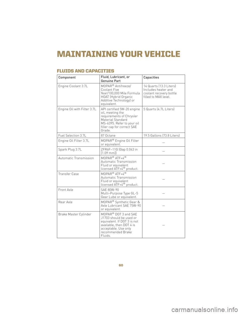
FLUIDS AND CAPACITIES
ComponentFluid, Lubricant, or
Genuine PartCapacities
Engine Coolant 3.7L MOPAR
®Antifreeze/
Coolant Five
Year/100,000 Mile Formula
HOAT (Hybrid Organic
Additive Technology) or
equivalent. 14 Quarts (13.3 Liters)
Includes heater and
coolant recovery bottle
filled to MAX level.
Engine Oil with Filter 3.7L API certified 5W-20 engine oil, meeting the
requirements of Chrysler
Material Standard
MS-6395. Refer to your oil
filler cap for correct SAE
Grade.5 Quarts (4.7L Liters)
Fuel Selection 3.7L 87 Octane 19.5 Gallons (73.8 Liters)
Engine Oil Filter 3.7L MOPAR
®Engine Oil Filter
or equivalent. —
Spark Plug 3.7L ZFR6F–11G (Gap 0.043 in
[1.09 mm]) —
Automatic Transmission MOPAR
®ATF+4®
Automatic Transmission
Fluid or equivalent
licensed ATF+4
®product. —
Transfer Case MOPAR®ATF+4®
Automatic Transmission
Fluid or equivalent
licensed ATF+4
®product.—
Front Axle SAE 80W-90
Multi–Purpose Type GL-5
Gear Lube or equivalent. —
Rear Axle MOPAR
®Synthetic Gear &
Axle Lubricant SAE 75W-90
or equivalent. —
Brake Master Cylinder MOPAR
®DOT 3 and SAE
J1703 should be used or
equivalent. If DOT 3 is not
available, then DOT 4 is
acceptable. Use only
recommended Brake
Fluids. —
MAINTAINING YOUR VEHICLE
60
Page 67 of 80
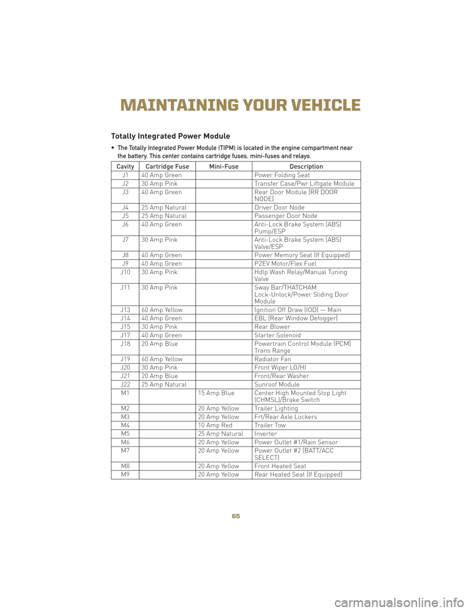
Totally Integrated Power Module
• The Totally Integrated Power Module (TIPM) is located in the engine compartment nearthe battery. This center contains cartridge fuses, mini-fuses and relays.
Cavity Cartridge Fuse Mini-Fuse Description
J1 40 Amp Green Power Folding Seat
J2 30 Amp Pink Transfer Case/Pwr Liftgate Module
J3 40 Amp Green Rear Door Module (RR DOOR
NODE)
J4 25 Amp Natural Driver Door Node
J5 25 Amp Natural Passenger Door Node
J6 40 Amp Green Anti-Lock Brake System (ABS)
Pump/ESP
J7 30 Amp Pink Anti-Lock Brake System (ABS)
Valve/ESP
J8 40 Amp Green Power Memory Seat (If Equipped)
J9 40 Amp Green PZEV Motor/Flex Fuel
J10 30 Amp Pink Hdlp Wash Relay/Manual Tuning
Valve
J11 30 Amp Pink Sway Bar/THATCHAM
Lock-Unlock/Power Sliding Door
Module
J13 60 Amp Yellow Ignition Off Draw (IOD) — Main
J14 40 Amp Green EBL (Rear Window Defogger)
J15 30 Amp Pink Rear Blower
J17 40 Amp Green Starter Solenoid
J18 20 Amp Blue Powertrain Control Module (PCM)
Trans Range
J19 60 Amp Yellow Radiator Fan
J20 30 Amp Pink Front Wiper LO/HI
J21 20 Amp Blue Front/Rear Washer
J22 25 Amp Natural Sunroof Module
M1 15 Amp Blue Center High Mounted Stop Light
(CHMSL)/Brake Switch
M2 20 Amp Yellow Trailer Lighting
M3 20 Amp Yellow Frt/Rear Axle Lockers
M4 10 Amp Red Trailer Tow
M5 25 Amp Natural Inverter
M6 20 Amp Yellow Power Outlet #1/Rain Sensor
M7 20 Amp Yellow Power Outlet #2 (BATT/ACC
SELECT)
M8 20 Amp Yellow Front Heated Seat
M9 20 Amp Yellow Rear Heated Seat (If Equipped)
65
MAINTAINING YOUR VEHICLE
Page 69 of 80
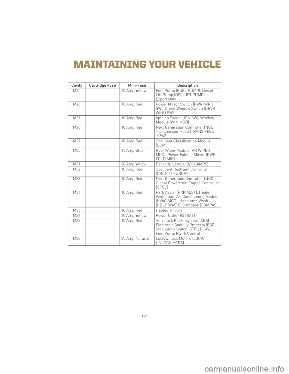
Cavity Cartridge Fuse Mini-FuseDescription
M25 20 Amp Yellow Fuel Pump (FUEL PUMP), Diesel
Lift Pump (DSL LIFT PUMP) —
Export Only
M26 10 Amp Red Power Mirror Switch (PWR MIRR
SW), Driver Window Switch (DRVR
WIND SW)
M27 10 Amp Red Ignition Switch (IGN SW), Window
Module (WIN MOD)
M28 10 Amp Red Next Generation Controller (NGC),
Transmission Feed (TRANS FEED),
J1962
M29 10 Amp Red Occupant Classification Module
(OCM)
M30 15 Amp Blue Rear Wiper Module (RR WIPER
MOD), Power Folding Mirror (PWR
FOLD MIR)
M31 20 Amp Yellow Back-Up Lamps (B/U LAMPS)
M32 10 Amp Red Occupant Restraint Controller
(ORC), TT EUROPE
M33 10 Amp Red Next Generation Controller (NGC),
Global Powertrain Engine Controller
(GPEC)
M34 10 Amp Red Park Assist (PRK ASST), Heater
Ventilation, Air Conditioning Module
(HVAC MOD), Headlamp Wash
(HDLP WASH), Compass (COMPAS)
M35 10 Amp Red Heated Mirrors
M36 20 Amp Yellow Power Outlet #3 (BATT)
M37 10 Amp Red Anti-Lock Brake System (ABS),
Electronic Stability Program (ESP),
Stop Lamp Switch (STP LP SW),
Fuel Pump Rly Hi Control
M38 25 Amp Natural Lock/Unlock Motors (LOCK/
UNLOCK MTRS)
67
MAINTAINING YOUR VEHICLE