wheel JEEP LIBERTY 2010 KK / 2.G User Guide
[x] Cancel search | Manufacturer: JEEP, Model Year: 2010, Model line: LIBERTY, Model: JEEP LIBERTY 2010 KK / 2.GPages: 80
Page 3 of 80
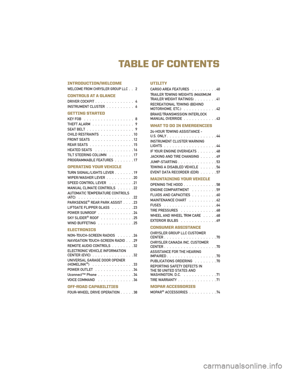
INTRODUCTION/WELCOME
WELCOME FROM CHRYSLER GROUP LLC.. 2
CONTROLS AT A GLANCE
DRIVER COCKPIT.............. 4
INSTRUMENT CLUSTER .......... 6
GETTING STARTED
KEYFOB .................. 8
THEFT ALARM............... 9
SEAT BELT ................. 9
CHILD RESTRAINTS ............10
FRONT SEATS ...............12
REAR SEATS ................15
HEATED SEATS ..............16
TILT STEERING COLUMN .........17
PROGRAMMABLE FEATURES .......17
OPERATING YOUR VEHICLE
TURN SIGNAL/LIGHTS LEVER .......19
WIPER/WASHER LEVER ..........20
SPEED CONTROL LEVER .........21
MANUAL CLIMATE CONTROLS ......22
AUTOMATIC TEMPERATURE CONTROLS
(ATC) ....................22
PARKSENSE
®REAR PARK ASSIST ....23
LIFTGATE FLIPPER GLASS ........23
POWER SUNROOF .............24
SKY SLIDER
®ROOF ............25
WINDBUFFETING .............25
ELECTRONICS
NON-TOUCH-SCREEN RADIOS ......26
NAVIGATION TOUCH-SCREEN RADIO . . . 29
REMOTE AUDIO CONTROLS ........32
ELECTRONIC VEHICLE INFORMATION
CENTER (EVIC) ...............32
UNIVERSAL GARAGE DOOR OPENER
(HOMELINK
®) ...............33
POWER OUTLET ..............34
Uconnect™ Phone .............34
VOICE COMMAND .............36
OFF-ROAD CAPABILITIES
FOUR-WHEEL DRIVE OPERATION .....38
UTILITY
CARGO AREA FEATURES.........40
TRAILER TOWING WEIGHTS (MAXIMUM
TRAILER WEIGHT RATINGS) ........41
RECREATIONAL TOWING (BEHIND
MOTORHOME, ETC.) ............42
BRAKE/TRANSMISSION INTERLOCK
MANUAL OVERRIDE ............43
WHAT TO DO IN EMERGENCIES
24-HOUR TOWING ASSISTANCE -
U.S. ONLY..................44
INSTRUMENT CLUSTER WARNING
LIGHTS ...................44
IF YOUR ENGINE OVERHEATS .......48
JACKING AND TIRE CHANGING ......49
JUMP-STARTING ..............53
TOWING A DISABLED VEHICLE ......56
EVENT DATA RECORDER (EDR) ......57
MAINTAINING YOUR VEHICLE
OPENING THE HOOD............58
ENGINE COMPARTMENT .........59
FLUIDS AND CAPACITIES .........60
MAINTENANCE CHART ..........62
FUSES ...................64
TIRE PRESSURES .............68
WHEEL AND WHEEL TRIM CARE .....68
EXTERIOR BULBS .............69
CONSUMER ASSISTANCE
CHRYSLER GROUP LLC CUSTOMER
CENTER...................70
CHRYSLER CANADA INC. CUSTOMER
CENTER ...................70
ASSISTANCE FOR THE HEARING
IMPAIRED ..................70
PUBLICATIONS ORDERING ........70
REPORTING SAFETY DEFECTS IN
THE 50 UNITED STATES AND
WASHINGTON, D.C. ............71
TIREWARRANTY..............71
MOPAR ACCESSORIES
MOPAR®ACCESSORIES ..........74
TABLE OF CONTENTS
Page 19 of 80
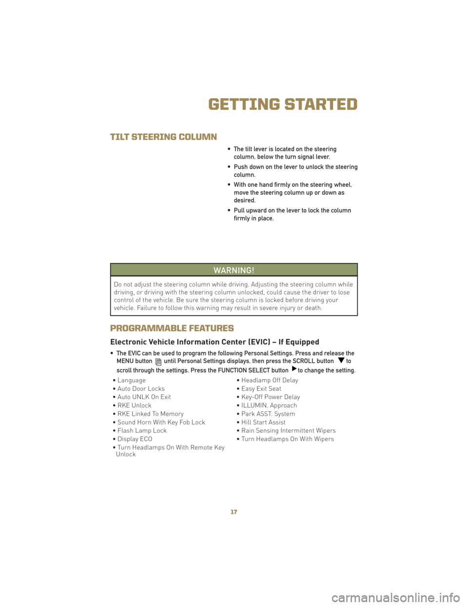
TILT STEERING COLUMN
• The tilt lever is located on the steeringcolumn, below the turn signal lever.
• Push down on the lever to unlock the steering column.
• With one hand firmly on the steering wheel, move the steering column up or down as
desired.
• Pull upward on the lever to lock the column firmly in place.
WARNING!
Do not adjust the steering column while driving. Adjusting the steering column while
driving, or driving with the steering column unlocked, could cause the driver to lose
control of the vehicle. Be sure the steering column is locked before driving your
vehicle. Failure to follow this warning may result in severe injury or death.
PROGRAMMABLE FEATURES
Electronic Vehicle Information Center (EVIC) – If Equipped
• The EVIC can be used to program the following Personal Settings. Press and release theMENU button
until Personal Settings displays, then press the SCROLL buttonto
scroll through the settings. Press the FUNCTION SELECT button
to change the setting.
• Language • Headlamp Off Delay
• Auto Door Locks • Easy Exit Seat
• Auto UNLK On Exit • Key-Off Power Delay
• RKE Unlock • ILLUMIN. Approach
• RKE Linked To Memory • Park ASST. System
• Sound Horn With Key Fob Lock • Hill Start Assist
• Flash Lamp Lock • Rain Sensing Intermittent Wipers
• Display ECO • Turn Headlamps On With Wipers
• Turn Headlamps On With Remote Key Unlock
17
GETTING STARTED
Page 34 of 80
Guide Me Home
• Press the NAV hard-key to access the Navigation Main Menu.
• Touch the GUIDE ME HOME soft-key to route you back to your home destination fromyour current location. Touch the GO soft-key to start your trip.
Map
• Press the NAV hard-key to access the Navigation Main Menu.
• Touch the MAP soft-key to display a map of your current position.
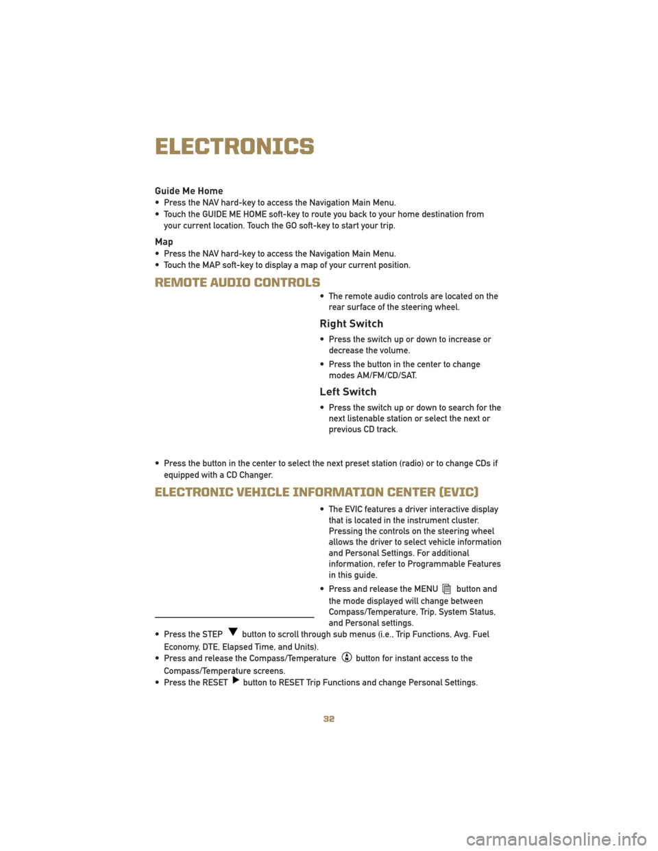
REMOTE AUDIO CONTROLS
• The remote audio controls are located on therear surface of the steering wheel.
Right Switch
• Press the switch up or down to increase ordecrease the volume.
• Press the button in the center to change modes AM/FM/CD/SAT.
Left Switch
• Press the switch up or down to search for thenext listenable station or select the next or
previous CD track.
• Press the button in the center to select the next preset station (radio) or to change CDs if equipped with a CD Changer.
ELECTRONIC VEHICLE INFORMATION CENTER (EVIC)
• The EVIC features a driver interactive displaythat is located in the instrument cluster.
Pressing the controls on the steering wheel
allows the driver to select vehicle information
and Personal Settings. For additional
information, refer to Programmable Features
in this guide.
• Press and release the MENU
button and
the mode displayed will change between
Compass/Temperature, Trip, System Status,
and Personal settings.
• Press the STEP
button to scroll through sub menus (i.e., Trip Functions, Avg. Fuel
Economy, DTE, Elapsed Time, and Units).
• Press and release the Compass/Temperature
button for instant access to the
Compass/Temperature screens.
• Press the RESET
button to RESET Trip Functions and change Personal Settings.
ELECTRONICS
32
Page 38 of 80
Phonebook (Uconnect™ Local) Edit
• Press the Phone button.
• (After the BEEP), say “phonebook”.
• (After the BEEP), say “new entry” or “list names” or “delete”.
• Follow the prompts.
Receiving A Call – Accept (And End)
• When an incoming call rings/is announced on Uconnect™, press the Phone button.
• To end a call, press the Phone button
.
Mute (Or Unmute) Microphone During Call
• During a call, press the Voice Command button.
• (After the BEEP), say “mute on” (or “mute off”).
Transfer Ongoing Call Between Handset And Vehicle
• During a call, press the Voice Command button.
• (After the BEEP), say “transfer call”.
Changing The Volume
• Start a dialogue by pressing the Phone button, then adjust the volume during a
normal call.
• Use the radio ON/OFF VOLUME rotary knob to adjust the volume to a comfortable level while the Uconnect™ system is speaking. Please note the volume setting for Uconnect™
is different than the audio system.
NOTE: To access the tutorial, press the Uconnect™ hard-key. After the BEEP, say
“tutorial”. Press any hard-key or touch the display to cancel the tutorial.
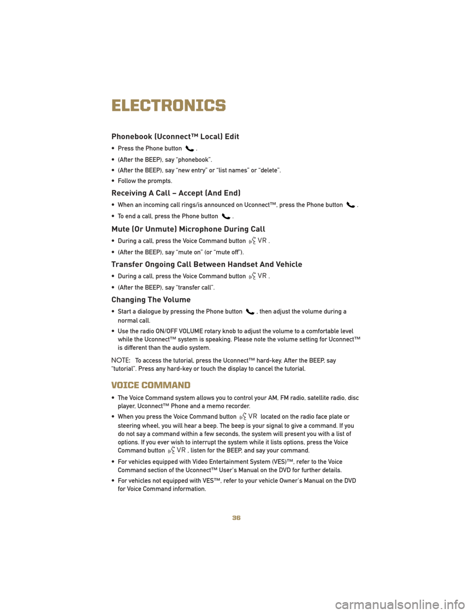
VOICE COMMAND
• The Voice Command system allows you to control your AM, FM radio, satellite radio, disc player, Uconnect™ Phone and a memo recorder.
• When you press the Voice Command button
located on the radio face plate or
steering wheel, you will hear a beep. The beep is your signal to give a command. If you
do not say a command within a few seconds, the system will present you with a list of
options. If you ever wish to interrupt the system while it lists options, press the Voice
Command button
, listen for the BEEP, and say your command.
• For vehicles equipped with Video Entertainment System (VES)™, refer to the Voice Command section of the Uconnect™ User's Manual on the DVD for further details.
• For vehicles not equipped with VES™, refer to your vehicle Owner's Manual on the DVD for Voice Command information.
ELECTRONICS
36
Page 40 of 80
FOUR-WHEEL DRIVE
OPERATION
WARNING!
• You or others could be injured ifyou leave the vehicle unattended
with the transfer case in the
NEUTRAL position without first
fully engaging the parking brake.
The transfer case NEUTRAL
position disengages both the front
driveshaft and rear driveshaft from
the powertrain, and it will allow
the vehicle to move even if the
transmission is in PARK. The
parking brake should always be
applied when the driver is not in
the vehicle.
MP1522 Command-Trac II®
Transfer Case
• The Command-TracII®transfer case
provides four positions:
• Two-wheel drive (2WD) high range
• Four-wheel drive (4WD LOCK) high range
• Four-wheel drive (4WD LOW) low range
• NEUTRAL (N)
2WD To 4WD LOCK
• Move transfer case lever to the desired position.
• Shifts between 2WD and 4WD LOCK can be done with the vehicle stopped or
in motion. With the vehicle in motion,
the transfer case will engage/
disengage faster if you momentarily
release the accelerator pedal after
moving the transfer case lever. • If the vehicle is stopped, the key must
be in the ON/RUN position.
• Shifts can not be completed if the key is in the ACC position.
4WD LOCK To 4WD LOW
• With the engine running, slow thevehicle speed to 2 to 3 mph (3 to
5 km/h) and shift the transmission into
NEUTRAL.
• While still rolling, move the transfer case lever to the 4WD LOW position.
• After the indicator light is ON (not flashing) shift the transmission into
gear.
• If the indicator light in the instrument cluster is flashing, the shift did not
occur and the current transfer case
position will be maintained.
• This transfer case is intended to be driven in the two-wheel drive position
(2WD) for normal street and highway
conditions such as dry, hard-surfaced
roads.
• When additional traction is required, select the transfer case 4WD LOCK
position or 4WD LOW position. This
position locks the front driveshaft and
rear driveshaft together and forces the
front and rear wheels to rotate at the
same speed.
• When operating in 4WD LOW, the engine speed is approximately three
times that of the 4WD LOCK position at
a given road speed. Take care not to
over-speed the engine and do not
exceed 25 mph (40 km/h).
• Use the transfer case NEUTRAL position for recreational towing only.
OFF-ROAD CAPABILITIES
38
Page 41 of 80
MP3022 Selec-Trac II®
Transfer Case
• The Selec-Trac II®active on-demand
transfer case provides four positions:
• Two-wheel drive (2WD) high range
• Four-wheel drive Auto (4WD AUTO) high range
• NEUTRAL (N)
• Four-wheel drive (4WD) low range
• This transfer case is intended to be driven in either the two-wheel drive
position (2WD) or the four-wheel drive
Auto position (4WD AUTO) for normal
street and highway conditions such as
dry, hard-surfaced roads.
• For added capability when traversing steep grades, rough terrain, or
extremely poor traction surfaces, select
the transfer case 4WD LOW position.
This position locks the front driveshaft
and rear driveshaft together and forces
the front and rear wheels to rotate at
the same speed while multiplying
engine torque.
• When operating in 4WD LOW, the engine speed is approximately three
times that of the 4WD LOCK position at
a given road speed. Take care not to
over-speed the engine and do not
exceed 25 mph (40 km/h).
• Use the transfer case NEUTRAL position for recreational towing only.
2WD To 4WD AUTO
• Move transfer case lever to the desired
position.
• Shifts between 2WD and 4WD AUTO can be done with the vehicle stopped or
in motion. With the vehicle in motion,
the transfer case will engage/
disengage faster if you momentarily
release the accelerator pedal after
moving the transfer case lever.
• If the vehicle is stopped, the key must be in the ON/RUN position.
• Shifts can not be completed if the key is in the ACC position.
4WD AUTO To 4WD LOW
• With the engine running, slow thevehicle speed to 2 to 3 mph (3 to
5 km/h) and shift the transmission into
NEUTRAL.
• While still rolling, move the transfer case lever to the 4WD LOW position.
• After the indicator light is ON (not flashing) shift the transmission into
gear.
• If the indicator light in the instrument cluster is flashing, the shift did not
occur and the current transfer case
position will be maintained.
39
OFF-ROAD CAPABILITIES
Page 44 of 80
RECREATIONAL TOWING
(BEHIND MOTORHOME,
ETC.)
Towing – Two-Wheel Drive
Models
• Recreational towing is allowed ONLY ifthe driveshaft is removed. Towing with
the rear wheels on the ground while
the driveshaft is connected can result
in severe transmission damage.
WARNING!
If the driveshaft is removed, the
vehicle can roll even if the
transmission is in PARK, which could
cause serious injury or death.
• The parking brake must be firmly engaged and the wheels chocked
during driveshaft removal and
installation. The parking brake must
remain engaged unless the vehicle is
securely and properly connected to the
tow vehicle, or the driveshaft is
completely reinstalled. See your
authorized dealer for proper driveshaft
removal and reinstallation procedures,
including flange orientation/alignment,
use of thread-locking compound,
proper bolt torque specifications, etc.
Towing – Four-Wheel Drive
Models
• Depress the brake pedal and turn theignition switch to ON/RUN with the
engine shut off.
• Shift the transmission into NEUTRAL.
• Shift the transfer case into NEUTRAL by holding down the NEUTRAL Pin
switch for four seconds until the LED
starts to blink. The LED will stop
blinking and remain on when the shift
is complete.
• Start the engine and shift into DRIVE to ensure there is no vehicle movement.
• Shut the engine off and shift the transmission into PARK.
• Place the ignition switch in the OFF position and remove the key.
• Apply the parking brake, attach the vehicle to the tow vehicle with a tow
bar and release the parking brake.
• Refer to your Owner's Manual on the DVD for further details.
UTILITY
42
Page 47 of 80
• When the malfunction indicator is illuminated, the system may not be able to detect orsignal low tire pressure as intended. TPMS malfunctions may occur for a variety of
reasons, including the installation of replacement or alternate tires or wheels on the
vehicle that prevent the TPMS from functioning properly. Always check the TPMS
malfunction telltale after replacing one or more tires or wheels on your vehicle, to ensure
that the replacement or alternate tires and wheels allow the TPMS to continue to function
properly.
CAUTION!
The TPMS has been optimized for the original equipment tires and wheels. TPMS
pressures and warning have been established for the tire size equipped on your
vehicle. Undesirable system operation or sensor damage may result when using
replacement equipment that is not of the same size, type, and/or style. Aftermarket
wheels can cause sensor damage. Do not use tire sealant from a can, or balance
beads if your vehicle is equipped with a TPMS, as damage to the sensors may result.
- Engine Temperature Warning Light
• This light warns of an overheated engine condition.
• If the light turns on and a warning chime sounds while driving, safely pull over and stopthe vehicle. If the A/C system is on, turn it off. Also, shift the transmission into NEUTRAL
and idle the vehicle. If the temperature reading does not return to normal, turn the
engine off immediately.
• We recommend that you do not operate the vehicle or engine damage will occur. Have the vehicle serviced immediately.
WARNING!
A hot engine cooling system is dangerous. You or others could be badly burned by
steam or boiling coolant. You may want to call an authorized service center for
service if your vehicle overheats.
45
WHAT TO DO IN EMERGENCIES
Page 51 of 80
CAUTION!
Driving with a hot cooling system could damage your vehicle. If the temperature
gauge reads HOT (H), pull over and stop the vehicle. Idle the vehicle with the air
conditioner turned off until the pointer drops back into the normal range. If the
pointer remains on HOT (H), and you hear continuous chimes, turn the engine off
immediately and call for service.
WARNING!
You or others can be badly burned by hot engine coolant (antifreeze) or steam from
your radiator. If you see or hear steam coming from under the hood, do not open the
hood until the radiator has had time to cool. Never try to open a cooling system
pressure cap when the radiator or coolant bottle is hot.
JACKING AND TIRE CHANGING
WARNING!
• Do not attempt to change a tire on the side of the vehicle close to moving traffic.Pull far enough off the road to avoid the danger of being hit when operating the
jack or changing the wheel.
• Getting under a jacked-up vehicle is dangerous. The vehicle could slip off the jack and fall on you. You could be crushed. Never get any part of your body under a
vehicle that is on a jack. If you need to get under a raised vehicle, take it to a
service center where it can be raised on a lift.
• The jack is designed to use as a tool for changing tires only. The jack should not be used to lift the vehicle for service purposes. The vehicle should be jacked on a
firm, level surface only. Avoid ice or slippery areas.
• If it is necessary to retrieve the spare tire from under the vehicle on the side of the vehicle close to moving traffic, pull far enough off the road to avoid the danger of
being hit.
49
WHAT TO DO IN EMERGENCIES
Page 52 of 80
Jack Location
• The scissor-type jack and tire changing toolsare located in the left rear trim panel behind
the second row seat.
Spare Tire Stowage
•To remove the spare tire, remove the
jack-handle components from the storage bin
in the left rear trim panel and assemble them.
• Lower the spare tire by turning the winchdrive nut, located in the rear cargo area
inside the vehicle, counterclockwise with the
jack-handle assembly until the spare tire is
on the ground with enough cable slack to
allow you to pull the spare tire out from
underneath the vehicle.
• When the spare is clear, tilt the retainer at the end of the cable and pull it through the center of the wheel.
Preparations For Jacking
• Park on a firm, level surface. Avoid ice or slippery areas.
• Set the parking brake and shift the automatic transmission into PARK.
• Turn the ignition to LOCK and turn on the Hazard Warning flasher.
• Block both the front and rear of the wheeldiagonally opposite of the jacking position.
For example, if changing the right front tire,
block the left rear wheel.
NOTE: Passengers should not remain in the
vehicle when the vehicle is being jacked.
WHAT TO DO IN EMERGENCIES
50