brake light JEEP PATRIOT 2014 1.G Owner's Manual
[x] Cancel search | Manufacturer: JEEP, Model Year: 2014, Model line: PATRIOT, Model: JEEP PATRIOT 2014 1.GPages: 568, PDF Size: 3.61 MB
Page 364 of 568
ABS is activated during braking under certain road or
stopping conditions. ABS-inducing conditions can in-
clude ice, snow, gravel, bumps, railroad tracks, loose
debris, or panic stops.
You may also experience the following when the brake
system goes into anti-lock mode:
•The ABS motor running (it may continue to run for a
short time after the stop).
• The clicking sound of solenoid valves.
• Brake pedal pulsations.
• A slight drop or fall away of the brake pedal at the end
of the stop.
These are all normal characteristics of ABS.WARNING!
The Anti-Lock Brake System (ABS) contains sophis-
ticated electronic equipment that may be susceptible
to interference caused by improperly installed or
high output radio transmitting equipment. This in-
terference can cause possible loss of Anti-Lock brak-
ing capability. Installation of such equipment should
be performed by qualified professionals.
All vehicle wheels and tires must be the same size and
type and tires must be properly inflated to produce
accurate signals for the computer.
362 STARTING AND OPERATING
Page 368 of 568
NOTE:Anytime the ESC system is in the “Full Off”
mode, ERM is disabled. Refer to “Electronic Stability
Control (ESC)” in this section for a complete explanation
of the available ESC modes.
WARNING!
Many factors, such as vehicle loading, road condi-
tions and driving conditions, influence the chance
that wheel lift or rollover may occur. ERM cannot
prevent all wheel lift or roll overs, especially those
that involve leaving the roadway or striking objects
or other vehicles. The capabilities of an ERM-
equipped vehicle must never be exploited in a reck-
less or dangerous manner which could jeopardize the
user’s safety or the safety of others.
Hill Descent Control (HDC) — If Equipped
This system maintains vehicle speed while descending
hills during off-road driving situations. HDC will auto-
matically apply the brakes to control downhill speed to
between 4 mph (7 km/h) and 6 mph (9 km/h) depending
on terrain. The system is activated by placing the vehicle
in “Off-Road” mode and placing the shift lever in LOW
or REVERSE. Refer to “Safe Off-Road Driving” in “Start-
ing and Operating” for further information.
When HDC is properly enabled, the “Hill
Decent Control Light” in the instrument cluster
will be illuminated.
HDC has the capability to sense terrain and will only
activate when the vehicle is descending a hill. It will not
activate on level ground. If desired, HDC can be fully
366 STARTING AND OPERATING
Page 369 of 568
deactivated by putting the vehicle into ESC “Full Off”
mode. This is done by pressing and holding the “ESC
Off” button for five seconds. Refer to “Electronic Stability
Control (ESC)” in this section of the manual.
HDC operation can be overridden with brake application
to slow the vehicle down below the HDC control speed.
Conversely, if more speed is desired during HDC control,
the accelerator pedal will increase vehicle speed like
normal. When either the brake or the accelerator is
released, HDC will control the vehicle back to the origi-
nal set speed.
HDC is only intended for low speed off-road driving. At
vehicle speeds above 31 mph (50 km/h) HDC will no
longer function. If the “HDC Indicator Light” begins to
flash this indicates that the brakes are getting too hot and
the vehicle should be stopped to allow the brakes to cool.WARNING!
HDC is only intended to assist the driver in control-
ling vehicle speed when descending hills. The driver
must remain attentive to the driving conditions and
is responsible for maintaining a safe vehicle speed.
Hill Start Assist (HSA)
The HSA system is designed to assist the driver when
starting a vehicle from a stop on a hill. HSA will maintain
the level of brake pressure the driver applied for a short
period of time after the driver takes their foot off of the
brake pedal. If the driver does not apply the throttle
during this short period of time, the system will release
brake pressure and the vehicle will roll down the hill. The
system will release brake pressure in proportion to
amount of throttle applied as the vehicle starts to move in
the intended direction of travel.5
STARTING AND OPERATING 367
Page 370 of 568
HSA Activation Criteria
The following criteria must be met in order for HSA to
activate:
•Vehicle must be stopped.
• Vehicle must be on a 7% (approximate) grade or
greater hill.
• Gear selection matches vehicle uphill direction (i.e.,
vehicle facing uphill is in forward gear; vehicle back-
ing uphill is in REVERSE gear).
WARNING!
There may be situations on minor hills with a loaded
vehicle, or while pulling a trailer, when the system
will not activate and slight rolling may occur. This
could cause a collision with another vehicle or object.
Always remember the driver is responsible for brak-
ing the vehicle.
Disabling/Enabling HSA
If you wish to turn on or off the HSA system, it can be done
using the Customer Programmable Features in the Elec-
tronic Vehicle Information Center (EVIC). Refer to “Elec-
tronic Vehicle Information Center (EVIC)” in “Understand-
ing Your Instrument Panel” for further information.
For vehicles not equipped with the EVIC, perform the
following steps:
NOTE: You must complete Steps 1 through 8 within 90
seconds.
1. Center the steering wheel (front wheels pointing straight forward).
2. Shift the transmission into NEUTRAL.
3. Apply the parking brake.
4. Start the engine.
368 STARTING AND OPERATING
Page 371 of 568
5. Release the clutch pedal (if equipped).
6. Rotate the steering wheel one-half turn to the left.
7. Press the “ESC Off” switch (located in the lowerswitch bank below the climate controls) four times
within 20 seconds. The “ESC Activation/Malfunction
Indicator Light” should turn on and turn off two
times.
8. Rotate the steering wheel back to center and then an additional half-turn to the right.
9. Turn the ignition switch to the OFF position and then back to the ON position. If the sequence was com-
pleted properly, the “ESC Activation/Malfunction In-
dicator Light” will blink several times to confirm HSA
is disabled.
10. Repeat these steps if you want to return this feature to it’s previous setting.Electronic Stability Control (ESC)
This system enhances directional control and stability of
the vehicle under various driving conditions. ESC cor-
rects for over-steering or under-steering of the vehicle by
applying the brake of the appropriate wheel to assist in
counteracting the over-steering or under-steering condi-
tion. Engine power may also be reduced to help the
vehicle maintain the desired path. ESC uses sensors in
the vehicle to determine the vehicle path intended by the
driver and compares it to the actual path of the vehicle.
When the actual path does not match the intended path,
ESC applies the brake of the appropriate wheel to assist
in counteracting the over-steer or under-steer condition
•Over-steer - when the vehicle is turning more than
appropriate for the steering wheel position.
• Under-steer - when the vehicle is turning less than
appropriate for the steering wheel position.
5
STARTING AND OPERATING 369
Page 423 of 568
WARNING!
•An improperly adjusted Weight Distributing Hitch
system may reduce handling, stability, braking
performance, and could result in a collision.
•
Weight Distributing Systems may not be compatible
with Surge Brake Couplers. Consult with your hitch
and trailer manufacturer or a reputable Recreational
Vehicle dealer for additional information.
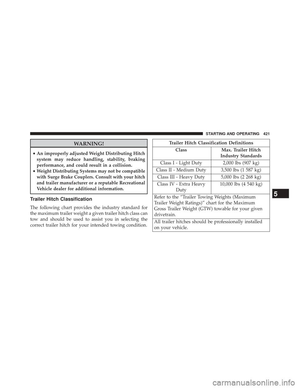
Trailer Hitch Classification
The following chart provides the industry standard for
the maximum trailer weight a given trailer hitch class can
tow and should be used to assist you in selecting the
correct trailer hitch for your intended towing condition.
Trailer Hitch Classification Definitions
Class Max. Trailer Hitch
Industry Standards
Class I - Light Duty 2,000 lbs (907 kg)
Class II - Medium Duty 3,500 lbs (1 587 kg) Class III - Heavy Duty 5,000 lbs (2 268 kg)
Class IV - Extra Heavy Duty 10,000 lbs (4 540 kg)
Refer to the “Trailer Towing Weights (Maximum
Trailer Weight Ratings)” chart for the Maximum
Gross Trailer Weight (GTW) towable for your given
drivetrain.
All trailer hitches should be professionally installed
on your vehicle.
5
STARTING AND OPERATING 421
Page 500 of 568
WARNING!
Riding the brakes can lead to brake failure and
possibly a collision. Driving with your foot resting or
riding on the brake pedal can result in abnormally
high brake temperatures, excessive lining wear, and
possible brake damage. You would not have your full
braking capacity in an emergency.
Brake Master Cylinder
The fluid level in the master cylinder should be checked
when performing under hood services, or immediately if
the brake system warning light is on.
Be sure to clean the top of the master cylinder area before
removing the cap. If necessary, add fluid to bring the
fluid level up to the requirements described on the brake
fluid reservoir. Fluid level can be expected to fall as thebrake pads wear. The brake fluid level should be checked
when the pads are replaced. However, low fluid level
may be caused by a leak and a checkup may be needed.
NOTE:
If your vehicle is equipped with a manual trans-
mission, the brake fluid reservoir supplies fluid to both
the brake system and the clutch release system. The two
systems are separated in the reservoir, and a leak in one
system will not affect the other system. The manual
transmission clutch release system should not require
fluid replacement during the life of the vehicle. If the
brake fluid reservoir is low and the brake system does
not indicate any leaks or other problems, it may be a
result of a leak in the hydraulic clutch release system. See
your local authorized dealer for service.
Use only manufacturer’s recommended brake fluid. Re-
fer to “Fluids, Lubricants, and Genuine Parts” in “Main-
taining Your Vehicle” for further information.
498 MAINTAINING YOUR VEHICLE
Page 516 of 568
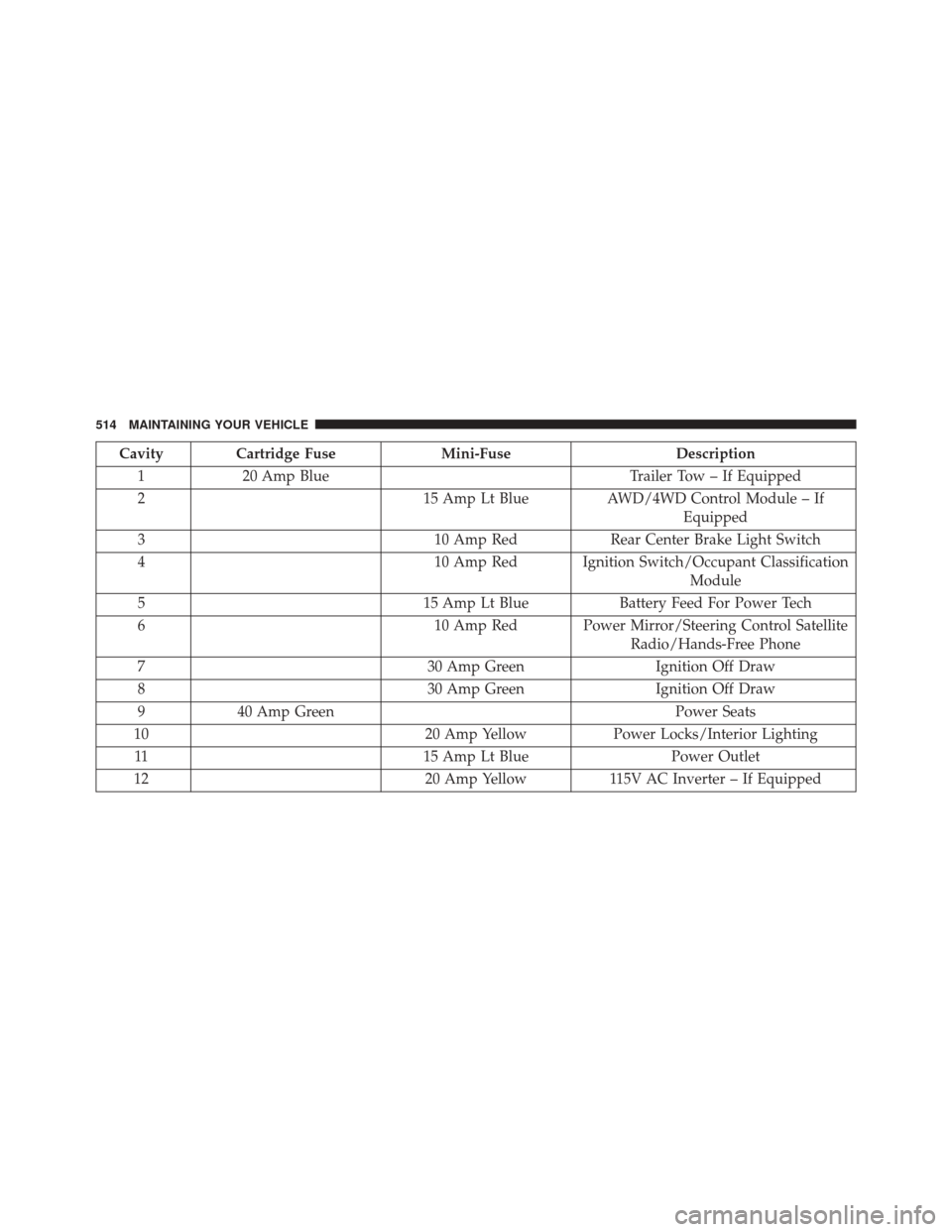
Cavity Cartridge FuseMini-FuseDescription
1 20 Amp Blue Trailer Tow – If Equipped
2 15 Amp Lt BlueAWD/4WD Control Module – If
Equipped
3 10 Amp RedRear Center Brake Light Switch
4 10 Amp Red Ignition Switch/Occupant Classification
Module
5 15 Amp Lt BlueBattery Feed For Power Tech
6 10 Amp Red Power Mirror/Steering Control Satellite
Radio/Hands-Free Phone
7 30 Amp GreenIgnition Off Draw
8 30 Amp GreenIgnition Off Draw
9 40 Amp Green Power Seats
10 20 Amp YellowPower Locks/Interior Lighting
11 15 Amp Lt BluePower Outlet
12 20 Amp Yellow115V AC Inverter – If Equipped
514 MAINTAINING YOUR VEHICLE
Page 529 of 568
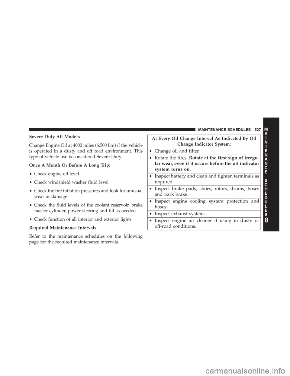
Severe Duty All Models
Change Engine Oil at 4000 miles (6,500 km) if the vehicle
is operated in a dusty and off road environment. This
type of vehicle use is considered Severe Duty.
Once A Month Or Before A Long Trip:
•Check engine oil level
• Check windshield washer fluid level
• Check the tire inflation pressures and look for unusual
wear or damage
• Check the fluid levels of the coolant reservoir, brake
master cylinder, power steering and fill as needed
• Check function of all interior and exterior lights
Required Maintenance Intervals.
Refer to the maintenance schedules on the following
page for the required maintenance intervals.At Every Oil Change Interval As Indicated By Oil Change Indicator System:
•Change oil and filter.
• Rotate the tires. Rotate at the first sign of irregu-
lar wear, even if it occurs before the oil indicator
system turns on.
• Inspect battery and clean and tighten terminals as
required.
• Inspect brake pads, shoes, rotors, drums, hoses
and park brake.
• Inspect engine cooling system protection and
hoses.
• Inspect exhaust system.
• Inspect engine air cleaner if using in dusty or
off-road conditions.
8
M
A I
N T
E
N
A
N
C E
S
C
H E
D
U L
E
SMAINTENANCE SCHEDULES 527
Page 548 of 568
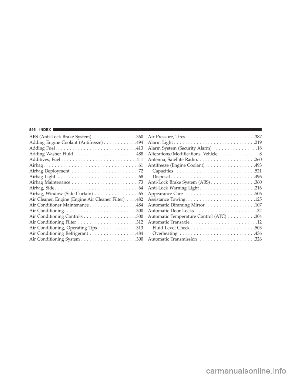
ABS (Anti-Lock Brake System)................360
Adding Engine Coolant (Antifreeze) ............494
Adding Fuel ............................ .413
Adding Washer Fluid ..................... .488
Additives, Fuel ...........................411
Airbag ..................................61
Airbag Deployment ........................72
Airbag Light .............................68
Airbag Maintenance ........................73
Airbag, Side ..............................64
Airbag, Window (Side Curtain) ................65
Air Cleaner, Engine (Engine Air Cleaner Filter) . . . .482
Air Conditioner Maintenance .................484
Air Conditioning ......................... .300
Air Conditioning Controls ...................300
Air Conditioning Filter .....................312
Air Conditioning, Operating Tips ..............313
Air Conditioning Refrigerant .................484
Air Conditioning System ....................300 Air Pressure, Tires
........................ .387
Alarm Light ............................ .219
Alarm System (Security Alarm) ................18
Alterations/Modifications, Vehicle ...............8
Antenna, Satellite Radio .....................260
Antifreeze (Engine Coolant) ..................493
Capacities ........................... .521
Disposal ............................. .496
Anti-Lock Brake System (ABS) ................360
Anti-Lock Warning Light ....................216
Appearance Care ........................ .506
Assistance Towing ........................ .125
Automatic Dimming Mirror ..................107
Automatic Door Locks ......................32
Automatic Temperature Control (ATC) ..........304
Automatic Transaxle ........................12
Fluid Level Check ...................... .503
Overheating .......................... .436
Automatic Transmission ................... .326
546 INDEX