wiring JEEP PATRIOT 2017 1.G Owners Manual
[x] Cancel search | Manufacturer: JEEP, Model Year: 2017, Model line: PATRIOT, Model: JEEP PATRIOT 2017 1.GPages: 421, PDF Size: 3.4 MB
Page 165 of 421
The air bag system must be ready to protect you in a
collision. The Occupant Restraint Controller (ORC) moni-
tors the internal circuits and interconnecting wiring asso-
ciated with the electrical Air Bag System Components.
Your vehicle may be equipped with the following Air Bag
System Components:
Air Bag System Components
•Occupant Restraint Controller (ORC)
• Air Bag Warning Light
•Steering Wheel and Column
• Instrument Panel
• Knee Impact Bolsters
• Driver and Front Passenger Air Bags
• Supplemental Side Air Bags
• Front and Side Impact Sensors
• Seat Belt Pretensioners
• Seat Track Position Sensors
• Seat Belt Buckle Switch
Air Bag Warning Light
The ORC monitors the readiness of the electronic
parts of the air bag system whenever the ignition
switch is in the START or ON/RUN position. If
the ignition switch is in the OFF position or in the
ACC position, the air bag system is not on and the air bags
will not inflate.
The ORC contains a backup power supply system that may
deploy the air bag system even if the battery loses power or
it becomes disconnected prior to deployment.
The ORC turns on the Air Bag Warning Light in the
instrument panel for approximately four to eight seconds
for a self-check when the ignition switch is first in the
ON/RUN position. After the self-check, the Air Bag Warn-
ing Light will turn off. If the ORC detects a malfunction in
any part of the system, it turns on the Air Bag Warning
Light, either momentarily or continuously. A single chime
will sound to alert you if the light comes on again after
initial startup.
The ORC also includes diagnostics that will illuminate the
instrument panel Air Bag Warning Light if a malfunction is
detected that could affect the air bag system. The diagnos-
tics also record the nature of the malfunction. While the air
5
SAFETY 163
Page 173 of 421
The SABICs may help reduce the risk of partial or complete
ejection of vehicle occupants through side windows in
certain rollover or side impact events.
The Occupant Restraint Controller (ORC) monitors the
internal circuits and interconnecting wiring associated
with electrical Air Bag System Components listed below:
Air Bag System Components
•Occupant Restraint Controller (ORC)
• Air Bag Warning Light
•Steering Wheel and Column
• Instrument Panel
• Knee Impact Bolsters
• Driver and Front Passenger Air Bags
• Supplemental Side Air Bags
• Front and Side Impact Sensors
• Seat Belt Pretensioners
• Seat Track Position Sensors
• Seat Belt Buckle Switch
If A Deployment Occurs
The front air bags are designed to deflate immediately after
deployment.
NOTE: Front and/or side air bags will not deploy in all
collisions. This does not mean something is wrong with the
air bag system.
If you do have a collision which deploys the air bags, any
or all of the following may occur:
• The air bag material may sometimes cause abrasions
and/or skin reddening to the occupants as the air bags
deploy and unfold. The abrasions are similar to friction
rope burns or those you might get sliding along a carpet
or gymnasium floor. They are not caused by contact with
chemicals. They are not permanent and normally heal
quickly. However, if you haven’t healed significantly
within a few days, or if you have any blistering, see your
doctor immediately.
• As the air bags deflate, you may see some smoke-like
particles. The particles are a normal by-product of the
process that generates the non-toxic gas used for air bag
inflation. These airborne particles may irritate the skin,
eyes, nose, or throat. If you have skin or eye irritation,
rinse the area with cool water. For nose or throat
5
SAFETY 171
Page 175 of 421
Maintaining Your Air Bag System
WARNING!
•Modifications to any part of the air bag system could
cause it to fail when you need it. You could be
injured if the air bag system is not there to protect
you. Do not modify the components or wiring, in-
cluding adding any kind of badges or stickers to the
steering wheel hub trim cover or the upper right side
of the instrument panel. Do not modify the front
bumper, vehicle body structure, or add aftermarket
side steps or running boards.
• It is dangerous to try to repair any part of the air bag
system yourself. Be sure to tell anyone who works on
your vehicle that it has an air bag system.
• Do not attempt to modify any part of your air bag
system. The air bag may inflate accidentally or may
not function properly if modifications are made.
Take your vehicle to an authorized dealer for any air
bag system service. If your seat, including your trim
cover and cushion, needs to be serviced in any way
(including removal or loosening/tightening of seat
attachment bolts), take the vehicle to your authorized
(Continued)
WARNING! (Continued)
dealer. Only manufacturer approved seat accessories
may be used. If it is necessary to modify the air bag
system for persons with disabilities, contact your
authorized dealer.
Event Data Recorder (EDR)
This vehicle is equipped with an event data recorder
(EDR). The main purpose of an EDR is to record, in certain
crash or near crash-like situations, such as an air bag
deployment or hitting a road obstacle, data that will assist
in understanding how a vehicle’s systems performed. The
EDR is designed to record data related to vehicle dynamics
and safety systems for a short period of time, typically 30
seconds or less. The EDR in this vehicle is designed to
record such data as:
•How various systems in your vehicle were operating;
• Whether or not the driver and passenger safety belts
were buckled/fastened;
• How far (if at all) the driver was depressing the accel-
erator and/or brake pedal; and,
• How fast the vehicle was traveling.5
SAFETY 173
Page 231 of 421
Towing Requirements — Trailer Lights And Wiring
Whenever you pull a trailer, regardless of the trailer size,
stoplights and turn signals on the trailer are required for
motoring safety.
The Trailer Tow Package may include a four- and seven-pin
wiring harness. Use a factory approved trailer harness and
connector.
NOTE:Do not cut or splice wiring into the vehicles wiring
harness.
The electrical connections are all complete to the vehicle
but you must mate the harness to a trailer connector. Refer
to the following illustrations.
Four-Pin Connector
1 — Female Pins 4 — Park
2 — Male Pin 5 — Left Stop/Turn
3 — Ground 6 — Right Stop/Turn
6
STARTING AND OPERATING 229
Page 418 of 421
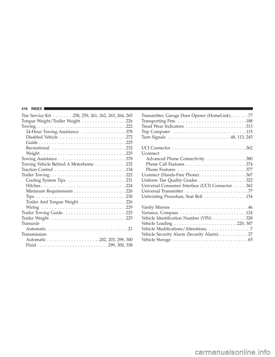
Tire Service Kit........258, 259, 261, 262, 263, 264, 265
Tongue Weight/Trailer Weight .................226
Towing ................................. .222
24-Hour Towing Assistance .................378
Disabled Vehicle ........................ .272
Guide ................................ .225
Recreational ........................... .232
Weight ............................... .225
Towing Assistance ......................... .378
Towing Vehicle Behind A Motorhome ............232
Traction Control .......................... .134
Trailer Towing ............................ .222
Cooling System Tips ..................... .231
Hitches ............................... .224
Minimum Requirements ....................226
Tips ................................. .230
Trailer And Tongue Weight ..................226
Wiring ............................... .229
Trailer Towing Guide ....................... .225
Trailer Weight ............................ .225
Transaxle Automatic ..............................21
Transmission Automatic ....................202, 203, 299, 300
Fluid .......................... .299, 300, 338Transmitter, Garage Door Opener (HomeLink)
.......77
Transporting Pets ......................... .188
Tread Wear Indicators ...................... .313
Trip Computer ............................115
Turn Signals ....................... .48, 113, 245
UCI Connector ........................... .362
Uconnect Advanced Phone Connectivity ...............380
Phone Call Features ...................... .374
Phone Features ......................... .377
Uconnect (Hands-Free Phone) ..................367
Uniform Tire Quality Grades ..................322
Universal Consumer Interface (UCI) Connector .....362
Universal
Transmitter ........................77
Untwisting Procedure, Seat Belt ................154
Vanity Mirrors .............................46
Variance, Compass ......................... .124
Vehicle Identification Number (VIN) .............328
Vehicle Loading ....................... .220, 307
Vehicle Modifications/Alterations .................7
Vehicle Security Alarm (Security Alarm) ...........27
Vehicle Storage .............................65
416 INDEX
Page 420 of 421

INSTALLATION OF RADIO TRANSMITTING
EQUIPMENT
Special design considerations are incorporated into this
vehicle’s electronic system to provide immunity to radio
frequency signals. Mobile two-way radios and telephone
equipment must be installed properly by trained person-
nel. The following must be observed during installation.
The positive power connection should be made directly
to the battery and fused as close to the battery as possible.
The negative power connection should be made to body
sheet metal adjacent to the negative battery connection.
This connection should not be fused.
Antennas for two-way radios should be mounted on the
roof or the rear area of the vehicle. Care should be used
in mounting antennas with magnet bases. Magnets may
affect the accuracy or operation of the compass on
vehicles so equipped.The antenna cable should be as short as practical and
routed away from the vehicle wiring when possible. Use
only fully shielded coaxial cable.
Carefully match the antenna and cable to the radio to
ensure a low Standing Wave Ratio (SWR).
Mobile radio equipment with output power greater than
normal may require special precautions.
All installations should be checked for possible interfer-
ence between the communications equipment and the
vehicle’s electronic systems.