technical specifications JEEP RENEGADE 2014 1.G Owners Manual
[x] Cancel search | Manufacturer: JEEP, Model Year: 2014, Model line: RENEGADE, Model: JEEP RENEGADE 2014 1.GPages: 212, PDF Size: 17.48 MB
Page 70 of 212
42)ESC performance features must not
induce the driver to take unnecessary
or unfounded risks. Your driving style must
always be suited to the road conditions,
visibility and traffic. The driver is, in any
case, responsible for safe driving.
43)For the correct operation of the TC
system, the tyres must of necessity be the
same make and type on all wheels, in
perfect condition and, above all, of the
prescribed type and size.
44)TC performance features must not
induce the driver to take unnecessary or
unfounded risks. Your driving style must
always be suited to the road conditions,
visibility and traffic. The driver is, in any
case, responsible for safe driving.
45)The TC system can’t overrule the
natural laws of physics, and can’t increase
the grip available according to the
condition of the road.
46)The TC system cannot prevent
accidents, including those due to excessive
speed on corners, driving on low-grip
surfaces or aquaplaning.
47)The capability of the TC must never be
tested irresponsibly and dangerously, in
such a way as to compromise personal
safety and the safety of others.
48)The PBA system can’t overrule the
natural laws of physics, and can’t increase
the grip available according to the
condition of the road.
49)The PBA system cannot prevent
accidents, including those due to excessive
speed on corners, driving on low-grip
surfaces or aquaplaning.50)The capability of the PBA system must
never be tested irresponsibly and
dangerously, in such a way as to
compromise the safety of the driver, the
other occupants of the vehicle or any other
road user.
51)The Hill Start Assist system is not a
parking brake; therefore, never leave the
vehicle without having engaged the electric
parking brake, turned the engine off and
engaged first gear, so that it is parked
in safe conditions (for further information
read the "Parking" paragraph in the
"Starting and driving" chapter).
52)There may be situations on small
gradients (less than 8%), with vehicle
laden, in which the Hill Start Assist system
may not activate, causing a slight reversing
motion and increasing the risk of collision
with another vehicle or object. The driver is,
in any case, responsible for safe driving.
53)DST is an aid for driving and does not
relieve the driver of responsibility for driving
the vehicle.
54)The performance of a vehicle with ERM
must never be tested in imprudent or
dangerous ways, with the possibility of
putting the safety of the driver or other
people at risk.
55)When towing trailers, the utmost
caution at the wheel is advised. Never
exceed the maximum permitted loads (see
the description in the "Weights" paragraph
in the "Technical Specifications" chapter).56)The TSC system cannot prevent
swerving for all trailers. If the system
activates during driving, reduce the speed,
stop the vehicle in a safe place and arrange
the load correctly to prevent the trailer
from swerving.
57)Prolonged use of the system may
overheat the braking system. If the brakes
overheat, the HDC system, when active,
will be gradually deactivated after suitably
informing the driver (LED on button off):
it can be reactivated only when the brakes
have cooled sufficiently. The distance
that can be covered depends on the
temperature of the brakes and therefore on
the gradient, load and speed of the
vehicle.
58)The performance of a vehicle with HDC
must never be tested in imprudent or
dangerous ways, with the possibility of
putting the safety of the driver or other
people at risk.
59)When "Systems partially disabled"
mode is selected, the intervention of the
TC function is limited to braking action on
the individual drive wheels and the
warning lights switches on in the
instrument panel. In "systems partially
disabled" mode, the engine torque value
that the ESC system may require will
not be guaranteed and the stability of the
vehicle will therefore be reduced.
60)With "Systems partially disabled" mode
selected, the TSC (Trailer Sway Control)
system is disabled.
61)Your driving style must always be
suited to the road conditions, visibility and
traffic. The driver is, in any case,
responsible for safe driving.
68
SAFETY
Page 75 of 212
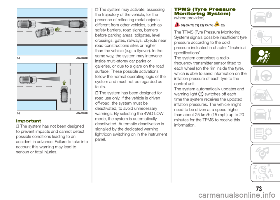
Important
❒The system has not been designed
to prevent impacts and cannot detect
possible conditions leading to an
accident in advance. Failure to take into
account this warning may lead to
serious or fatal injuries.❒The system may activate, assessing
the trajectory of the vehicle, for the
presence of reflecting metal objects
different from other vehicles, such as
safety barriers, road signs, barriers
before parking areas, tollgates, level
crossings, gates, railways, objects near
road constructions sites or higher
than the vehicle (e.g. a flyover). In the
same way, the system may intervene
inside multi-storey car parks or
galleries, or due to a glare on the road
surface. These possible activations
follow the normal operating logic of the
system and must not be regarded as
faults.
❒The system has been designed for
road use only. If the vehicle is driven
off-road, the system must be
deactivated, to avoid unnecessary
warnings. By selecting the 4WD LOW
mode, the system is automatically
deactivated. Automatic deactivation is
signalled by the dedicated warning
light/icon switching on in the instrument
panel.
TPMS (Tyre Pressure
Monitoring System)
(where provided)
68) 69) 70) 71) 72) 73) 74)32)
The TPMS (Tyre Pressure Monitoring
System) signals possible insufficient tyre
pressure according to the cold
pressure indicated in chapter "Technical
specifications".
The system comprises a radio-
frequency transmitter sensor fitted to
each wheel (on the rim inside the tyre),
which is able to send information on the
inflation pressure of each tyre to the
control unit.
The system automatically updates and
warning light
switches off each
time the system receives the updated
inflation pressures. The vehicle might
need to be driven at a speed higher
than about 25 km/h (15 mph) up to 20
minutes for the TPMS to receive this
information.
61J0A0083C
62J0A0336C
73
Page 132 of 212
WARNING
133)Before replacing the bulb, wait for the
exhaust ducts to cool down: RISK OF
BURNS!
134)Changes or repairs to the electrical
system carried out incorrectly and without
due consideration for the technical
specifications of the system may lead to
malfunctioning and generate a fire hazard.
135)Halogen bulbs contain pressurised
gas. If they break, glass fragments could fly
everywhere.
WARNING
52)Halogen bulbs must be handled by
holding the metallic part only. Touching the
transparent part of the bulb with your
fingers may reduce the intensity of the
emitted light and even reduce the lifespan
of the bulb. In the case of accidental
contact, rub the lamp with a cloth and
spirit and leave to dry.
REPLACING FUSES
INTRODUCTION
136) 137) 138) 139) 140)
53) 54)
Fuse extracting pliers
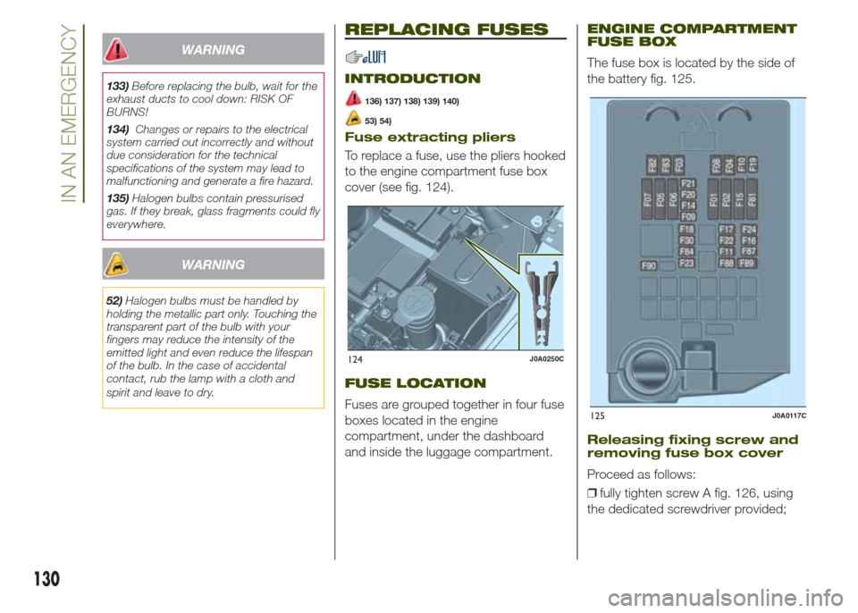
To replace a fuse, use the pliers hooked
to the engine compartment fuse box
cover (see fig. 124).
FUSE LOCATION
Fuses are grouped together in four fuse
boxes located in the engine
compartment, under the dashboard
and inside the luggage compartment.
ENGINE COMPARTMENT
FUSE BOX
The fuse box is located by the side of
the battery fig. 125.
Releasing fixing screw and
removing fuse box cover
Proceed as follows:
❒fully tighten screw A fig. 126, using
the dedicated screwdriver provided;
124J0A0250C
125J0A0117C
130
IN AN EMERGENCY
Page 141 of 212
146)The jack is a tool developed and
designed only for changing a wheel, if a
tyre gets punctured or damaged, on the
vehicle with which it is supplied or on other
vehicles of the same model. It must not
be used, for example, to jack other vehicle
models or objects. Never use the jack to
carry out maintenance or repairs under the
vehicle. Never position yourself under a
jacked vehicle. Should it be necessary to
work under the vehicle, contact a Jeep
Dealership. Incorrectly positioning the jack
may cause the vehicle to fall: use it only
in the positions indicated. Do not use the
jack for loads higher than the one shown
on its label.
147)The space-saver wheel cannot be
fitted with snow chains. If a front (drive) tyre
is punctured and chains are needed, use
a standard wheel from the rear axle and
install the space-saver wheel on the rear
axle. In this way, with two normal drive
wheels at the front axle, it is possible to use
snow chains.
148)Incorrect hub cap assembly, if
present, may cause it to come off when the
vehicle is moving. Never tamper with the
inflation valve. Never introduce tools of any
kind between the rim and the tyre. Check
tyre and space-saver wheel pressures
regularly, complying with the values given in
the "Technical specifications" chapter.TIREKIT
(where provided)
DESCRIPTION
The TireKit is located in the luggage
compartment inside a dedicated
container.
The container is also equipped with a
screwdriver, the tow hook and the
refuelling adaptor.
To access the TireKit, open the tailgate,
remove the reconfigurable load platform
and lift the carpet.
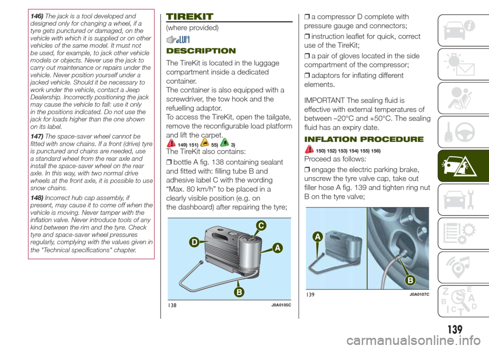
149) 151)55)3)The TireKit also contains:
❒bottle A fig. 138 containing sealant
and fitted with: filling tube B and
adhesive label C with the wording
“Max. 80 km/h” to be placed in a
clearly visible position (e.g. on
the dashboard) after repairing the tyre;❒a compressor D complete with
pressure gauge and connectors;
❒instruction leaflet for quick, correct
use of the TireKit;
❒a pair of gloves located in the side
compartment of the compressor;
❒adaptors for inflating different
elements.
IMPORTANT The sealing fluid is
effective with external temperatures of
between –20°C and +50°C. The sealing
fluid has an expiry date.
INFLATION PROCEDURE
150) 152) 153) 154) 155) 156)
Proceed as follows:
❒engage the electric parking brake,
unscrew the tyre valve cap, take out
filler hose A fig. 139 and tighten ring nut
B on the tyre valve;
138J0A0105C
139J0A0107C
139
Page 153 of 212
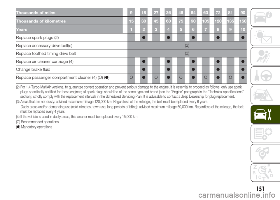
Thousands of miles 9 18 27 36 45 54 63 72 81 90
Thousands of kilometres 15 30 45 60 75 90 105 120 135 150
Years12345678910
Replace spark plugs (2)●●●●●
Replace accessory drive belt(s)(3)
Replace toothed timing drive belt(3)
Replace air cleaner cartridge (4)●●●●●
Change brake fluid●●●●●
Replace passenger compartment cleaner (4) (O) (●)O●O●O●O●O●
(2) For 1.4 Turbo MultiAir versions, to guarantee correct operation and prevent serious damage to the engine, it is essential to proceed as follows: only use spark
plugs specifically certified for these engines; all spark plugs should be of the same type and brand (see the “Engine” paragraph in the “Technical specifications”
section); strictly comply with the replacement intervals in the Scheduled Servicing Plan. It is advisable to contact a Jeep Dealership for plug replacement.
(3) Areas that are not dusty: advised maximum mileage 120,000 km. Regardless of the mileage, the belt must be replaced every 6 years.
Dusty areas and/or demanding use (cold climates, town use, long periods of idling): advised maximum mileage 60,000 km. Regardless of the mileage, thebelt
must be replaced every 4 years.
(4) If the vehicle is used in dusty areas, this cleaner must be replaced every 15,000 km.
(O) Recommended operations
(●) Mandatory operations
151
Page 160 of 212
ENGINE OIL
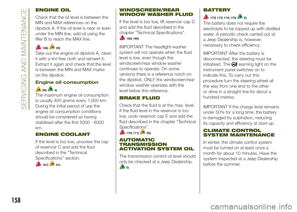
Check that the oil level is between the
MIN and MAX references on the
dipstick A. If the oil level is near or even
under the MIN line, add oil using the
filler B to reach the MAX line.
166)59)
Take out the engine oil dipstick A, clean
it with a lint-free cloth and reinsert it.
Extract it again and check that the level
is between the MIN and MAX marks
on the dipstick.
Engine oil consumption
60)4)
The maximum engine oil consumption
is usually 400 grams every 1,000 km.
During the initial period of use the
engine oil consumption conditions
should be considered as having
stabilised after the first 5000 - 6000
km.
ENGINE COOLANT
If the level is too low, unscrew the cap
of reservoir C and add the fluid
described in the "Technical
Specifications" section.
167)61)
WINDSCREEN/REAR
WINDOW WASHER FLUID
If the level is too low, lift reservoir cap D
and add the fluid described in the
chapter "Technical Specifications".
168) 169)
IMPORTANT The headlight washer
system will not operate when the fluid
level is low, even though the
windscreen/rear window washer
continues to operate. On some
versions there is a reference notch on
the dipstick: ONLY the windscreen/rear
window washer operates with the
level below this reference.
BRAKE FLUID
Check that the fluid is at the max. level.
If the fluid level in the reservoir is too
low, undo reservoir cap E and add the
fluid described in the chapter "Technical
Specifications".
170) 171)62)
AUTOMATIC
TRANSMISSION
ACTIVATION SYSTEM OIL
The transmission control oil level should
only be checked at a Jeep Dealership.
5)
BATTERY
172) 173) 174) 175)6)
The battery does not require the
electrolyte to be topped up with distilled
water. A periodic check carried out at
a Jeep Dealership is, however,
necessary to check efficiency.
IMPORTANT After the battery is
disconnected, the steering must be
initialised. The
warning light on the
instrument panel switches on to
indicate this. To carry out this
procedure turn the steering wheel all
the way from one end to the other
or drive in a straight line for about a
hundred metres.
IMPORTANT If the charge level remains
under 50% for a long time, the battery
is damaged by sulphation, reducing
its capacity and efficiency at start-up.
CLIMATE CONTROL
SYSTEM MAINTENANCE
In winter, the climate control system
must be turned on at least once a
month for about 10 minutes. Have the
system inspected at a Jeep Dealership
before the summer.
158
SERVICING AND MAINTENANCE
Page 167 of 212
TECHNICAL SPECIFICATIONS
Everything you may find useful for
understanding how your vehicle
is made and works is contained in this
chapter and illustrated with data, tables
and graphics. For the enthusiasts and
the technician, but also just for those
who want to know every detail of their
vehicle.IDENTIFICATION DATA....................166
ENGINE ..........................................167
WHEELS .........................................169
DIMENSIONS ..................................171
WEIGHTS........................................174
SUPPLIES .......................................175
FLUIDS AND LUBRICANTS ............176
PERFORMANCE .............................178
FUEL CONSUMPTION ....................178
CO2 EMISSIONS ............................179
PRESCRIPTIONS FOR HANDLING
THE VEHICLE AT THE END OF ITS
LIFE ................................................179
165
Page 168 of 212
IDENTIFICATION
DATA
VEHICLE IDENTIFICATION
NUMBER
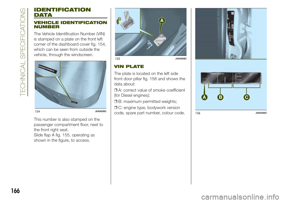
The Vehicle Identification Number (VIN)
is stamped on a plate on the front left
corner of the dashboard cover fig. 154,
which can be seen from outside the
vehicle, through the windscreen.
This number is also stamped on the
passenger compartment floor, next to
the front right seat.
Slide flap A fig. 155, operating as
shown in the figure, to access.
VIN PLATE
The plate is located on the left side
front door pillar fig. 156 and shows the
data about:
❒A: correct value of smoke coefficient
(for Diesel engines);
❒B: maximum permitted weights;
❒C: engine type, bodywork version
code, spare part number, colour code.
Z
FA520VP70P000016
ZFA520VP70P000016
154J0A0030C
155J0A0028C
156J0A0446C
166
TECHNICAL SPECIFICATIONS
Page 170 of 212
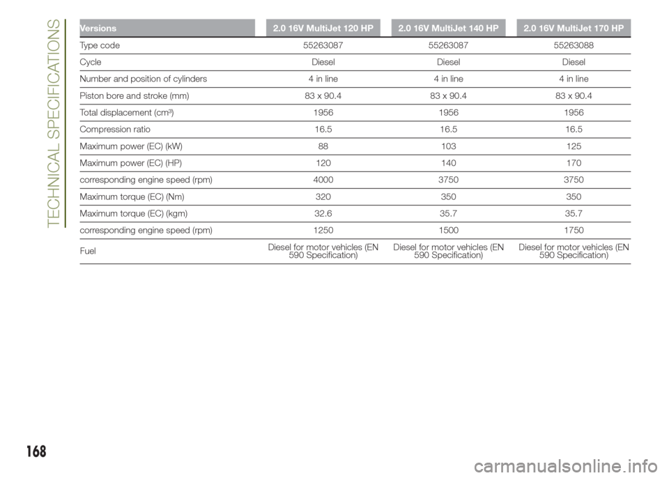
Versions 2.0 16V MultiJet 120 HP 2.0 16V MultiJet 140 HP 2.0 16V MultiJet 170 HP
Type code 55263087 55263087 55263088
Cycle Diesel Diesel Diesel
Number and position of cylinders 4 in line 4 in line 4 in line
Piston bore and stroke (mm) 83 x 90.4 83 x 90.4 83 x 90.4
Total displacement (cm³) 1956 1956 1956
Compression ratio 16.5 16.5 16.5
Maximum power (EC) (kW) 88 103 125
Maximum power (EC) (HP) 120 140 170
corresponding engine speed (rpm) 4000 3750 3750
Maximum torque (EC) (Nm) 320 350 350
Maximum torque (EC) (kgm) 32.6 35.7 35.7
corresponding engine speed (rpm) 1250 1500 1750
FuelDiesel for motor vehicles (EN
590 Specification)Diesel for motor vehicles (EN
590 Specification)Diesel for motor vehicles (EN
590 Specification)
168
TECHNICAL SPECIFICATIONS
Page 172 of 212
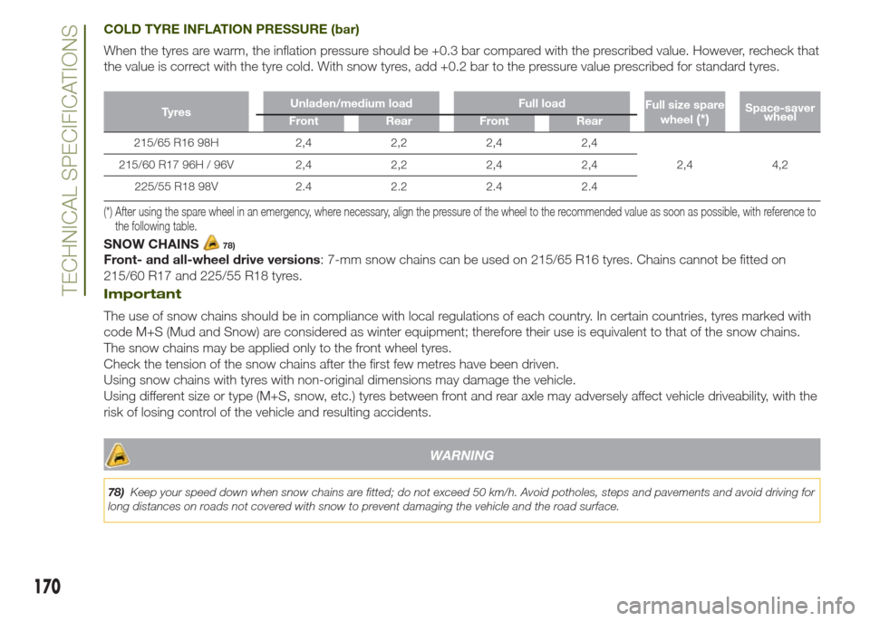
COLD TYRE INFLATION PRESSURE (bar)
When the tyres are warm, the inflation pressure should be +0.3 bar compared with the prescribed value. However, recheck that
the value is correct with the tyre cold. With snow tyres, add +0.2 bar to the pressure value prescribed for standard tyres.
Ty r e sUnladen/medium load Full load
Full size spare
wheel(*)Space-saver
wheel
Front Rear Front Rear
215/65 R16 98H 2,4 2,2 2,4 2,4
2,4 4,2 215/60 R17 96H / 96V 2,4 2,2 2,4 2,4
225/55 R18 98V 2.4 2.2 2.4 2.4
(*) After using the spare wheel in an emergency, where necessary, align the pressure of the wheel to the recommended value as soon as possible, with reference to
the following table.
SNOW CHAINS78)
Front- and all-wheel drive versions: 7-mm snow chains can be used on 215/65 R16 tyres. Chains cannot be fitted on
215/60 R17 and 225/55 R18 tyres.
Important
The use of snow chains should be in compliance with local regulations of each country. In certain countries, tyres marked with
code M+S (Mud and Snow) are considered as winter equipment; therefore their use is equivalent to that of the snow chains.
The snow chains may be applied only to the front wheel tyres.
Check the tension of the snow chains after the first few metres have been driven.
Using snow chains with tyres with non-original dimensions may damage the vehicle.
Using different size or type (M+S, snow, etc.) tyres between front and rear axle may adversely affect vehicle driveability, with the
risk of losing control of the vehicle and resulting accidents.
WARNING
78)Keep your speed down when snow chains are fitted; do not exceed 50 km/h. Avoid potholes, steps and pavements and avoid driving for
long distances on roads not covered with snow to prevent damaging the vehicle and the road surface.
170
TECHNICAL SPECIFICATIONS