warning JEEP RENEGADE 2015 1.G Workshop Manual
[x] Cancel search | Manufacturer: JEEP, Model Year: 2015, Model line: RENEGADE, Model: JEEP RENEGADE 2015 1.GPages: 678, PDF Size: 29.84 MB
Page 206 of 678
•Zone (1A)
– Up and down arrow (Left)
– Title number
•Zone (1B)
– External Temp. (Centered)
– Title (Centered)
– Time (Centered)
•Zones (1, 2 & 3)
– Date
– Compass
– Time
– External Temp.
•Zone (2)
– Double scale (Centered)
•Zone (2 & 3)
– Ignition Button Info (Centered)
•Zone (4)
– Speed Warning Title
•Zone (5)
– Text (Centered)
– Side Distance Warning
– Park Sense: Front & Rear
•Zone (6)
– Odometer Digits (Left)
– Odometer Unit (Right)
– Side Distance Warning
– Park Sense: Front & Rear
•Zone (7)
– Red Telltales (Centered)
•Zone (8)
– Amber Telltales (Centered)
204 GETTING TO KNOW YOUR INSTRUMENT PANEL
Page 215 of 678
Restore Default Settings
Selecting this item, and you can reset and restore the
default settings.
Vehicle Setup
This menu item allows you to change the settings for the
following:
•Display
•Units of measure
•Clock and Data
•Safety
•Safety and Assistance
•Lights
•Doors and Locks
•Compass (If Equipped)
Vehicles Equipped With Multifunctional Display
Reconfigurable:Menu items#Display#(you can select
only the items#See Phone#and#See Navigation,##Secu-
rity,#and#Safety & Assistance#(only#Volume Alerts#is
selectable) are present.
All other entries are displayed and selected on the
display of the Uconnect® system.
“Display”
By selecting the#Display,#you can access the following
settings:
•Language: allows you to select the language in which
to display the information/warnings.
•See Phone:allows you to view, on the instrument
cluster display, the information relating to Phone
mode displayed on the display of the Uconnect®
system.
5
GETTING TO KNOW YOUR INSTRUMENT PANEL 213
Page 216 of 678
•See Navigation:allows you to view, on the instrument
cluster display, information relating to the navigation
mode.
$Units Of Measure$
By selecting the item#Units of measure,#you can select
the unit of measure to use for displaying various magni-
tudes.
Possible options are:
•US
•Metric
•Custom
$Clock & Data$
By selecting the item,#Clock & Data#you can adjust the
clock.
Possible options are:
•Set Time: adjust hours/minutes
•Set Format: adjust the time format#12h#(12 hours) or
#24h#(24 hours)
•Set Date: adjust day/month/year
Safety
By selecting the item “Safety,” you can make the follow-
ing adjustments:
•Speed Warning:
Set the vehicle speed limit (km/h or mph), which the
driver is notified through a visual and acoustic signaling
(display of a message and a symbol on the display).
•Speed Belt Buzzer:
This function is only viewable when the Seat Belt Re-
minder (SBR) system is active.
214 GETTING TO KNOW YOUR INSTRUMENT PANEL
Page 217 of 678
•Hill Start Assist:
Activation/Deactivation of the Hill Start Assist system.
$Safety & Assistance$
By selecting the item#Safety & Assistance,#you can make
the following adjustments:
•FCW: a selection of operating modes of the system
Forward Collision Warning Plus
•FCW Sensitivity: a selection of the#readiness#of
intervention of the Forward Collision Warning Plus
system, based on the distance to the obstacle
•ParkSense: a selection of the type of information
provided by ParkSense
•Rear Parks. Vol.: selection of the volume of acoustic
signals provided by ParkSense
•ParkSense Vol.: a selection of the volume of acoustic
signals provided by ParkSense
•Front Parks. Vol.: selection of the volume of the beeps
provided by ParkSense
•Side Dist. Warn. Vol. (If equipped) : a selection of the
volume of the beeps of SideSense system
•Side Dist. Warn. (if Equipped) : Select the type of
reporting provided by SideSense system
•Auto Wipers: enabling/disabling the automatic opera-
tion of wipers in the event of rain
•LaneSense Warn.: a selection of the#readiness#of
intervention of LaneSense
•LaneSense Force: selection of the force to be applied to
the steering wheel to put the car in the roadway
through the system of electrical drive, in case of
operation of the system LaneSense
5
GETTING TO KNOW YOUR INSTRUMENT PANEL 215
Page 223 of 678
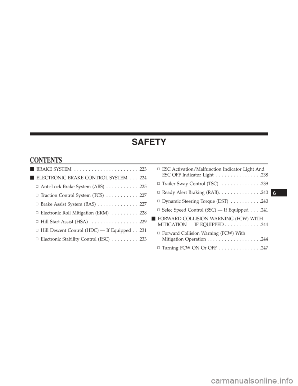
SAFETY
CONTENTS
!BRAKE SYSTEM.......................223
!ELECTRONIC BRAKE CONTROL SYSTEM . . . .224
▫Anti-Lock Brake System (ABS)............225
▫Traction Control System (TCS)............227
▫Brake Assist System (BAS)...............227
▫Electronic Roll Mitigation (ERM)..........228
▫Hill Start Assist (HSA).................229
▫Hill Descent Control (HDC) — If Equipped . . .231
▫Electronic Stability Control (ESC)..........233
▫ESC Activation/Malfunction Indicator Light And
ESC OFF Indicator Light................238
▫Trailer Sway Control (TSC)..............239
▫Ready Alert Braking (RAB)...............240
▫Dynamic Steering Torque (DST)...........240
▫Selec Speed Control (SSC) — If Equipped . . . .241
!FORWARD COLLISION WARNING (FCW) WITH
MITIGATION — IF EQUIPPED.............244
▫Forward Collision Warning (FCW) With
Mitigation Operation...................244
▫Turning FCW ON Or OFF...............247
6
Page 224 of 678
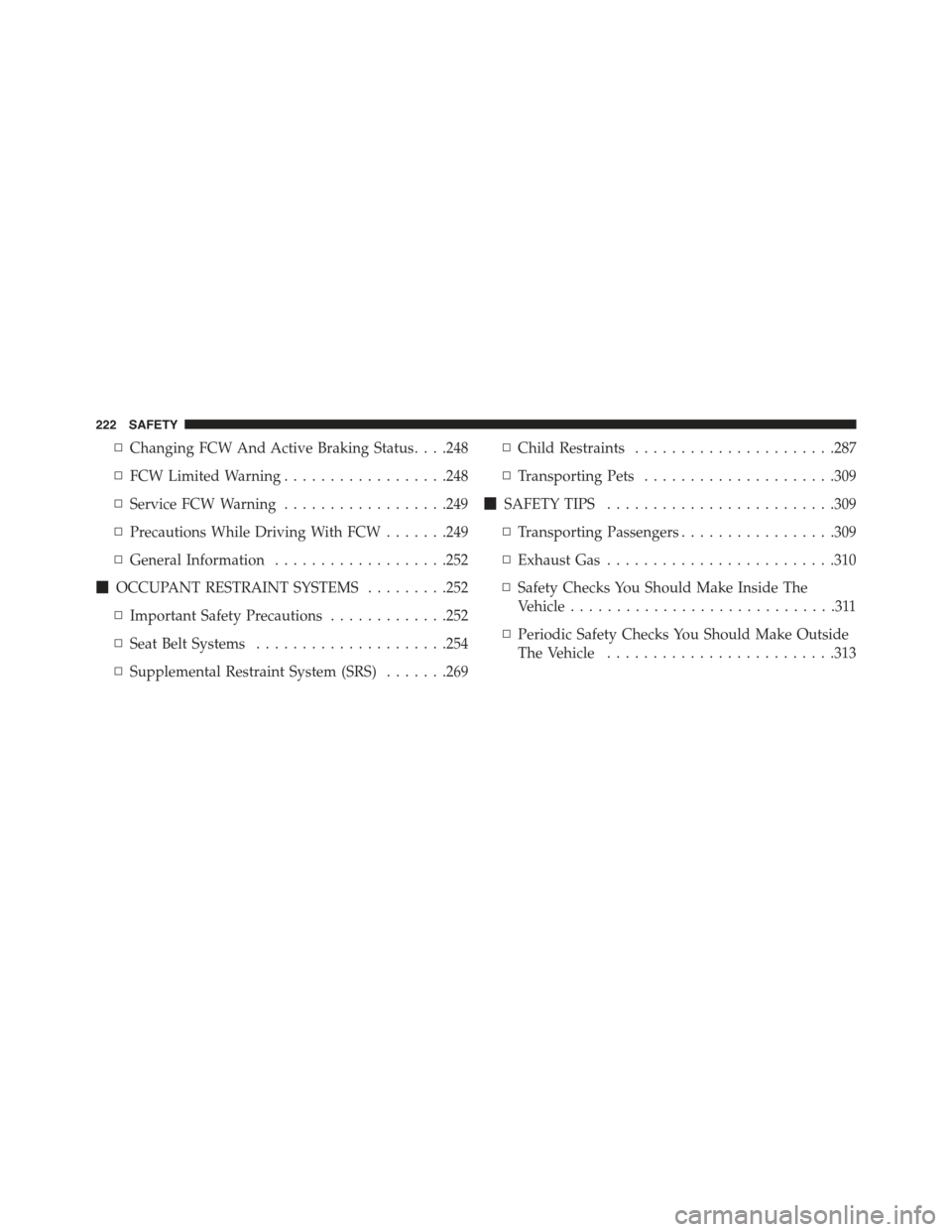
▫Changing FCW And Active Braking Status. . . .248
▫FCW Limited Warning..................248
▫Service FCW Warning..................249
▫Precautions While Driving With FCW.......249
▫General Information...................252
!OCCUPANT RESTRAINT SYSTEMS.........252
▫Important Safety Precautions.............252
▫Seat Belt Systems.....................254
▫Supplemental Restraint System (SRS).......269
▫Child Restraints......................287
▫Transporting Pets.....................309
!SAFETY TIPS.........................309
▫Transporting Passengers.................309
▫Exhaust Gas.........................310
▫Safety Checks You Should Make Inside The
Vehicle.............................311
▫Periodic Safety Checks You Should Make Outside
The Vehicle.........................313
222 SAFETY
Page 225 of 678
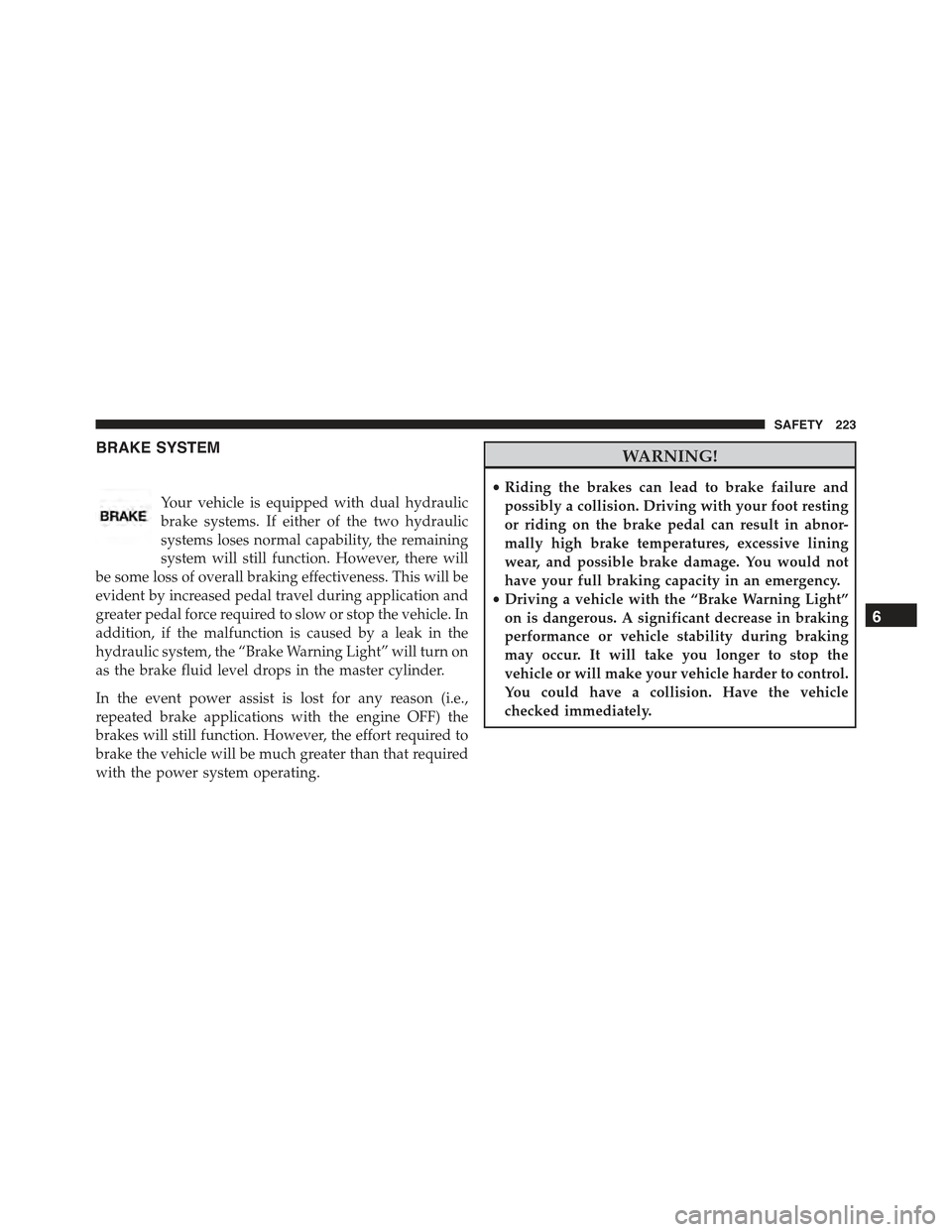
BRAKE SYSTEM
Your vehicle is equipped with dual hydraulic
brake systems. If either of the two hydraulic
systems loses normal capability, the remaining
system will still function. However, there will
be some loss of overall braking effectiveness. This will be
evident by increased pedal travel during application and
greater pedal force required to slow or stop the vehicle. In
addition, if the malfunction is caused by a leak in the
hydraulic system, the “Brake Warning Light” will turn on
as the brake fluid level drops in the master cylinder.
In the event power assist is lost for any reason (i.e.,
repeated brake applications with the engine OFF) the
brakes will still function. However, the effort required to
brake the vehicle will be much greater than that required
with the power system operating.
WARNING!
•Riding the brakes can lead to brake failure and
possibly a collision. Driving with your foot resting
or riding on the brake pedal can result in abnor-
mally high brake temperatures, excessive lining
wear, and possible brake damage. You would not
have your full braking capacity in an emergency.
•Driving a vehicle with the “Brake Warning Light”
on is dangerous. A significant decrease in braking
performance or vehicle stability during braking
may occur. It will take you longer to stop the
vehicle or will make your vehicle harder to control.
You could have a collision. Have the vehicle
checked immediately.
6
SAFETY 223
Page 226 of 678
ELECTRONIC BRAKE CONTROL SYSTEM
This system enhances directional control and stability of
the vehicle under various driving conditions. ESC cor-
rects for oversteering or understeering of the vehicle by
applying the brake of the appropriate wheel to assist in
counteracting the oversteer or understeer condition. En-
gine power may also be reduced to help the vehicle
maintain the desired path.
ESC uses sensors in the vehicle to determine the vehicle
path intended by the driver and compares it to the actual
path of the vehicle. When the actual path does not match
the intended path, ESC applies the brake of the appro-
priate wheel to assist in counteracting the oversteer or
understeer condition.
•Oversteer - when the vehicle is turning more than
appropriate for the steering wheel position.
•Understeer - when the vehicle is turning less than
appropriate for the steering wheel position.
The “ESC Activation/Malfunction Indicator Light” lo-
cated in the instrument cluster will start to flash as soon
as the tires lose traction and the ESC system becomes
active. The “ESC Activation/Malfunction Indicator
Light” also flashes when the TCS is active. If the “ESC
Activation/Malfunction Indicator Light” begins to flash
during acceleration, ease up on the accelerator and apply
as little throttle as possible. Be sure to adapt your speed
and driving to the prevailing road conditions.
WARNING!
The Electronic Stability Control (ESC) cannot pre-
vent the natural laws of physics from acting on the
vehicle, nor can it increase the traction afforded by
prevailing road conditions. ESC cannot prevent col-
lisions, including those resulting from excessive
speed in turns, driving on very slippery surfaces, or
(Continued)
224 SAFETY
Page 227 of 678
WARNING!(Continued)
hydroplaning. ESC also cannot prevent collisions
resulting from loss of vehicle control due to inappro-
priate driver input for the conditions. Only a safe,
attentive, and skillful driver can prevent collisions.
The capabilities of an ESC equipped vehicle must
never be exploited in a reckless or dangerous manner
which could jeopardize the user ’s safety or the safety
of others.
Anti-Lock Brake System (ABS)
The Anti-Lock Brake System (ABS) is designed to aid the
driver in maintaining vehicle control under adverse
braking conditions. The system operates with a separate
computer to modulate hydraulic pressure, to prevent
wheel lock-up and help avoid skidding on slippery
surfaces.
All vehicle wheels and tires must be the same size and
type, and tires must be properly inflated, to produce
accurate signals for the computer.
WARNING!
Significant over or under-inflation of tires or mixing
sizes of tires or wheels on the vehicle can lead to loss
of braking effectiveness.
The ABS conducts a low-speed self-test at approximately
12 mph (20 km/h). If you have your foot lightly on the
brake while this test is occurring, you may feel slight
pedal movement. The movement can be more apparent
on ice and snow. This is normal.
The ABS pump motor runs during the self-test at 12 mph
(20 km/h) and during an ABS stop. The pump motor
makes a low humming noise during operation, which is
normal.
6
SAFETY 225
Page 228 of 678
WARNING!
•Pumping of the Anti-Lock Brakes will diminish
their effectiveness and may lead to a collision.
Pumping makes the stopping distance longer. Just
press firmly on your brake pedal when you need to
slow down or stop.
•The ABS cannot prevent the natural laws of phys-
ics from acting on the vehicle, nor can it increase
braking or steering efficiency beyond that afforded
by the condition of the vehicle brakes and tires or
the traction afforded.
•The ABS cannot prevent collisions, including those
resulting from excessive speed in turns, following
another vehicle too closely, or hydroplaning.
•The capabilities of an ABS equipped vehicle must
never be exploited in a reckless or dangerous
manner, which could jeopardize the user’s safety or
the safety of others.
CAUTION!
The ABS is subject to possible detrimental effects of
electronic interference caused by improperly in-
stalled aftermarket radios or telephones.
NOTE:During severe braking conditions, a pulsing sen-
sation may occur and a clicking noise will be heard. This
is normal, indicating that the ABS is functioning.
•Do not “ride” the brakes by resting your foot on the
pedal. This could overheat the brakes and result in
unpredictable braking action, longer stopping dis-
tances, or brake damage.
•When descending mountains or hills, repeated braking
can cause brake fade with loss of braking control.
Avoid repeated heavy braking by downshifting the
transmission or locking out overdrive whenever pos-
sible.
226 SAFETY