warning light JEEP RENEGADE 2015 1.G Owner's Manual
[x] Cancel search | Manufacturer: JEEP, Model Year: 2015, Model line: RENEGADE, Model: JEEP RENEGADE 2015 1.GPages: 220, PDF Size: 34.11 MB
Page 163 of 220
- Malfunction Indicator Light (MIL)
The Malfunction Indicator Light (MIL) is part of an onboard diagnostic system called
OBD II that monitors engine and automatic transmission control systems. The light
will illuminate when the key is in the MAR/RUN position before engine start. If the
bulb does not come on when turning the key from STOP/OFF to MAR/RUN, have the
condition checked promptly.
Certain conditions, poor fuel quality, etc., may illuminate the light after engine start.
The vehicle should be serviced if the light stays on through several of your typical driving
cycles. In most situations, the vehicle will drive normally and will not require towing.
CAUTION!
Prolonged driving with the Malfunction Indicator Light (MIL) on could causedamage to the engine control system. It also could affect fuel economy anddriveability. If the MIL is flashing, severe catalytic converter damage and powerloss will soon occur. Immediate service is required.
WARNING!
A malfunctioning catalytic converter, as referenced above, can reach higher tempera-
tures than in normal operating conditions. This can cause a fire if you drive slowly or
park over flammable substances such as dry plants, wood, cardboard, etc. This could
result in death or serious injury to the driver, occupants or others.
– SERV (Service) 4WD Indicator Light
If the light stays on or comes on during driving, it means that the 4WD system is not
functioning properly and that service is required. We recommend you drive to the
nearest service center and have the vehicle serviced immediately.
-ElectronicStabilityControl(ESC)Activation/MalfunctionIndicatorLight
If this indicator light flashes during acceleration, apply as little throttle as possible.
While driving, ease up on the accelerator. Adapt your speed and driving to the
prevailing road conditions. To improve the vehicle's traction when starting off in deep
snow, sand or gravel, it may be desirable to switch the ESC system off.
INSTRUMENT CLUSTER INDICATOR LIGHTS
- Turn Signal Indicator
The arrows will flash with the exterior turn signals when the turn signal lever is
operated. A tone will chime, and a EVIC/DID message will appear if either turn signal
is left on for more than 1 mile (1.6 km).
NOTE:
If either indicator flashes at a rapid rate, check for a defective outside light bulb.
WHAT TO DO IN EMERGENCIES
161
Page 164 of 220
- High Beam Indicator
Indicates that headlights are on high beam.
- Front Fog Light Indicator
This indicator will illuminate when the front fog lights are on.
- Vehicle Security Light
This light will flash rapidly for approximately 15 seconds when the vehicle security
alarm is arming. The light will flash at a slower speed continuously after the alarm is
set. The security light will also come on for about three seconds when the ignition is
first turned on.
- Electronic Speed Control ON Indicator
This indicator will illuminate when the electronic speed control has been activated to
the “ON” position.
- Electronic Speed Control SET Indicator
This indicator will illuminate when the cruising speed has been set.
- Hill Descent Control Indicator — If Equipped
This indicator will illuminate when Hill Descent Control (HDC) has been selected
using the Hill Descent Control Switch.
- Park/Headlight ON Indicator
This indicator will illuminate when the park lights or headlights are turned on.
- Electronic Stability Control (ESC) OFF Indicator Light
This light indicates the Electronic Stability Control (ESC) is off.
- Windshield Washer Fluid Low Indicator
This indicator will illuminate when the windshield washer fluid is low.
- Door Ajar Indicator
This indicator will illuminate when a door(s) is left ajar and not fully closed.
- Forward Collision Warning (FCW) OFF Indicator
NOTE:
• The default status of FCW is “On.” This allows the system to warn you of a possible
collision with the vehicle in front of you.
• The forward collision button is located on the switch panel below the Uconnect®
display.
WHAT TO DO IN EMERGENCIES
162
Page 174 of 220
WARNING!
Raising the vehicle higher than necessary can make the vehicle less stable. It
could slip off the jack and hurt someone near it. Raise the vehicle only enough to
remove the tire.
6. Remove the wheel bolts and tire.
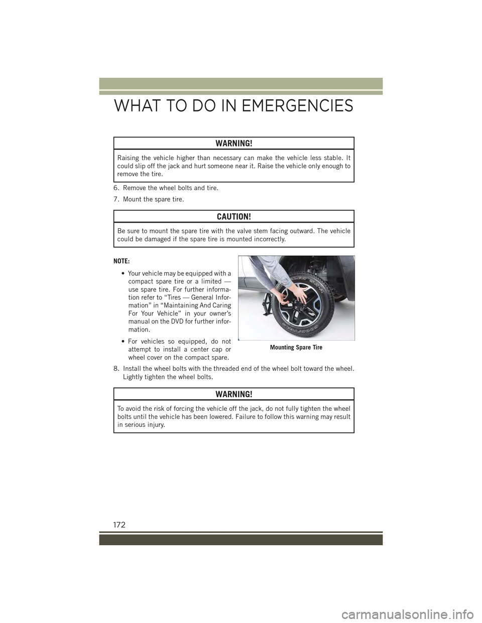
7. Mount the spare tire.
CAUTION!
Be sure to mount the spare tire with the valve stem facing outward. The vehicle
could be damaged if the spare tire is mounted incorrectly.
NOTE:
• Your vehicle may be equipped with a
compact spare tire or a limited —
use spare tire. For further informa-
tion refer to “Tires — General Infor-
mation” in “Maintaining And Caring
For Your Vehicle” in your owner’s
manual on the DVD for further infor-
mation.
• For vehicles so equipped, do not
attempt to install a center cap or
wheel cover on the compact spare.
8. Install the wheel bolts with the threaded end of the wheel bolt toward the wheel.
Lightly tighten the wheel bolts.
WARNING!
To avoid the risk of forcing the vehicle off the jack, do not fully tighten the wheel
bolts until the vehicle has been lowered. Failure to follow this warning may result
in serious injury.
Mounting Spare Tire
WHAT TO DO IN EMERGENCIES
172
Page 175 of 220
9. Lower the vehicle to the ground by turning the jack handle counterclockwise.
10. Finish tightening the wheel bolts. Push down on the wrench while at the end of
the handle for increased leverage. Tighten the wheel bolts in a star pattern until
each wheel bolt has been tightened twice. The correct torque specification for
the wheel bolts is 63 Ft-Lbs (86 Nm) for steel wheels and 89 Ft-Lbs (120 Nm)
for aluminum wheels. If in doubt about the correct tightness, have them
checked with a torque wrench by your authorized dealer or at a service station.
11. Securely stow the jack, tools, chocks and flat tire.
WARNING!
A loose tire or jack thrown forward in a collision or hard stop could endanger the
occupants of the vehicle. Always stow the jack parts and the spare tire in the
places provided. Have the deflated (flat) tire repaired or replaced immediately.
Road Tire Installation
1. Mount the road tire on the axle.
2. Install the remaining wheel bolts with the threaded end of the wheel bolt toward
the wheel. Lightly tighten the wheel bolts.
WARNING!
To avoid the risk of forcing the vehicle off the jack, do not tighten the lug nuts fully
until the vehicle has been lowered. Failure to follow this warning may result in
serious injury.
3. Lower the vehicle to the ground by turning the jack handle counterclockwise.
4. Finish tightening the wheel bolts. Push down on the wrench while at the end ofthe handle for increased leverage. Tighten the wheel bolts in a star pattern untileach wheel bolt has been tightened twice. The correct torque specification for thewheel bolts is 63 Ft-Lbs (86 Nm) for steel wheels and 89 Ft-Lbs (120 Nm) foraluminum wheels. If in doubt about the correct tightness, have them checkedwith a torque wrench by your authorized dealer or at a service station.
5. Lower the jack until it is free. Remove the wheel chocks. Stow the jack and tools
back in the proper storage location. Release the Electric Park Brake before driving
the vehicle.
6. After 25 miles (40 km) check the wheel bolt torque with a torque wrench to
ensure that all wheel bolts are properly seated against the wheel.
WHAT TO DO IN EMERGENCIES
173
Page 176 of 220
JUMP-STARTING PROCEDURES
If your vehicle has a discharged battery it can be jump-started using a set of jumper
cables and a battery in another vehicle or by using a portable battery booster pack.
Jump-starting can be dangerous if done improperly so please follow the procedures
in this section carefully.
NOTE:
When using a portable battery booster pack follow the manufacturer’s operating
instructions and precautions.
CAUTION!
Do not use a portable battery booster pack or any other booster source with a
system voltage greater than 12 Volts or damage to the battery, starter motor,
alternator or electrical system may occur.
WARNING!
Do not attempt jump-starting if the battery is frozen. It could rupture or explode
and cause personal injury.
Preparations For Jump-Start
The battery in your vehicle is located in the front of the engine compartment, behind
the left headlight assembly.
NOTE:
The positive battery post is covered with a protective cap. Lift up on the cap to gain
access to the positive battery post.
WARNING!
• Take care to avoid the radiator cooling fan whenever the hood is raised. It can
start anytime the ignition switch is ON. You can be injured by moving fan
blades.
• Remove any metal jewelry such as rings, watch bands and bracelets that could
make an inadvertent electrical contact. You could be seriously injured.
• Batteries contain sulfuric acid that can burn your skin or eyes and generate
hydrogen gas which is flammable and explosive. Keep open flames or sparks
away from the battery.
Proceed as follows:
1. Set the Electric Park Brake, shift the automatic transmission into PARK (manual
transmission in NEUTRAL) and turn the ignition to STOP/OFF.
2. Turn off the heater, radio, and all unnecessary electrical accessories.
WHAT TO DO IN EMERGENCIES
174
Page 191 of 220
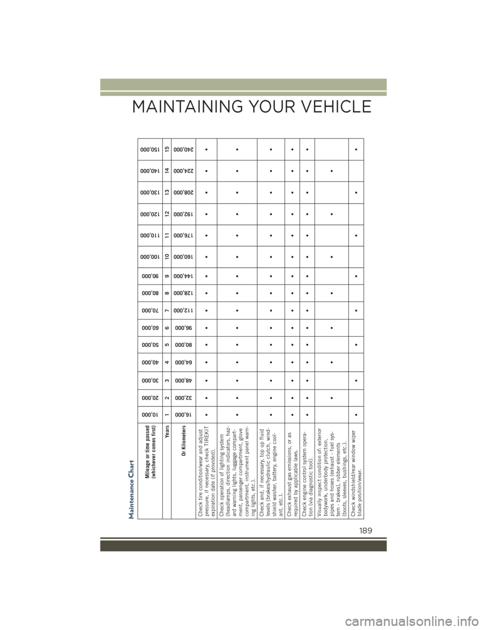
Maintenance Chart
Mileage or time passed(whichever comes first)
10,000
20,000
30,000
40,000
50,000
60,000
70,000
80,000
90,000
100,000
110,000
120,000
130,000
140,000
150,000
Years 1 2 3 4 5 6 7 8 9 10 11 12 13 14 15
Or Kilometers
16,000
32,000
48,000
64,000
80,000
96,000
112,000
128,000
144,000
160,000
176,000
192,000
208,000
224,000
240,000
Check tire condition/wear and adjustpressure, if necessary, check TIREKITexpiration date (if provided).
•• • • •• • •• • • • • • •
Check operation of lighting system(headlamps, direction indicators, haz-ard warning lights, luggage compart-ment, passenger compartment, glovecompartment, instrument panel warn-ing lights, etc.).
•• • • •• • •• • • • • • •
Check and, if necessary, top up fluidlevels (brakes/hydraulic clutch, wind-shield washer, battery, engine cool-ant, etc.).
•• • • •• • •• • • • • • •
Check exhaust gas emissions, or asrequired by applicable laws.
•• • • •• • •• • • • • • •
Check engine control system opera-tion (via diagnostic tool).
•• • • •• • •• • • • • • •
Visually inspect condition of: exteriorbodywork, underbody protection,pipes and hoses (exhaust - fuel sys-tem - brakes), rubber elements(boots, sleeves, bushings, etc.).
•••• • • •
Check windshield/rear window wiperblade position/wear.
•• ••• • • •
MAINTAINING YOUR VEHICLE
189
Page 194 of 220
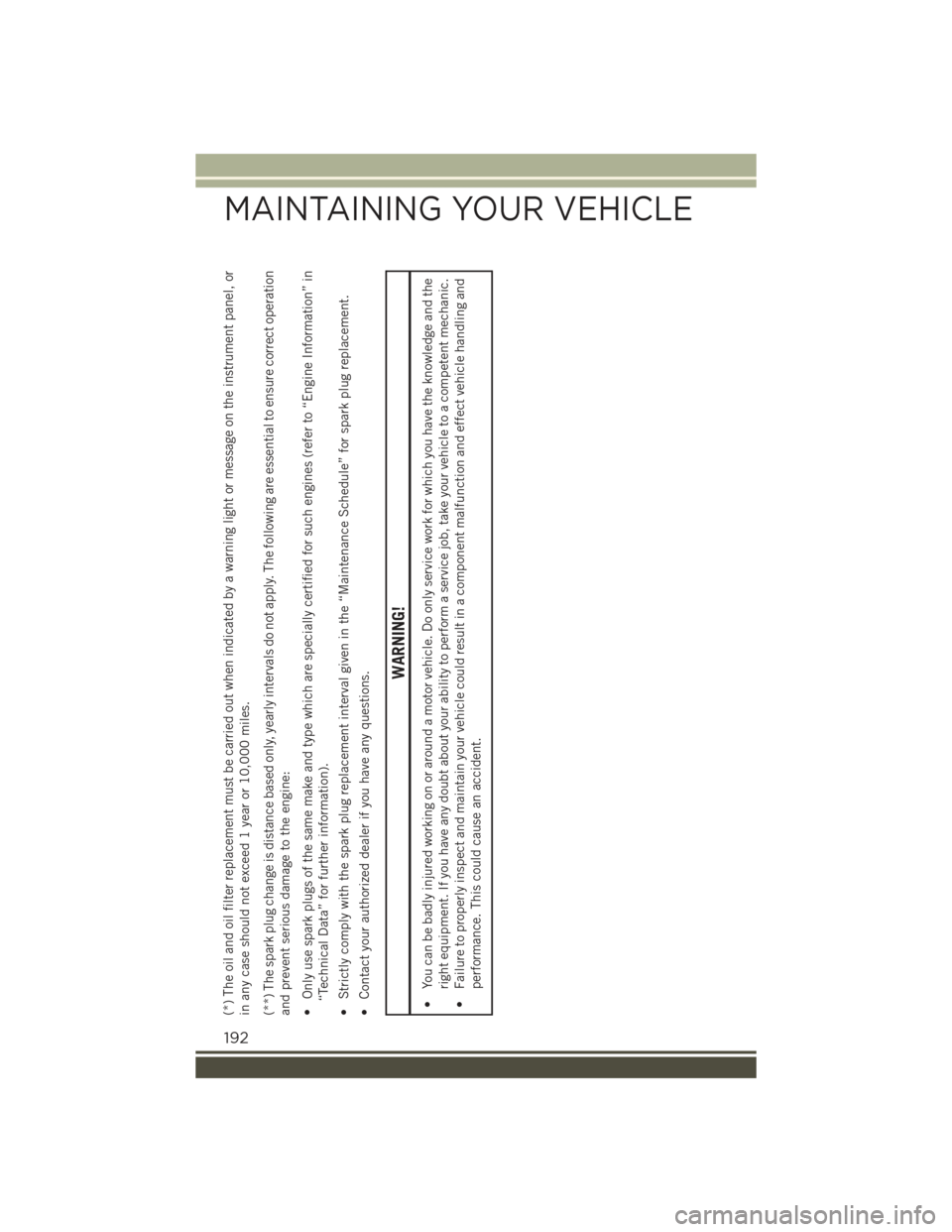
(*) The oil and oil filter replacement must be carried out when indicated by a warning light or message on the instrument panel, orin any case should not exceed 1 year or 10,000 miles.(**) The spark plug change is distance based only, yearly intervals do not apply. The following are essential to ensure correct operationand prevent serious damage to the engine:• Only use spark plugs of the same make and type which are specially certified for such engines (refer to “Engine Information” in“Technical Data” for further information).• Strictly comply with the spark plug replacement interval given in the “Maintenance Schedule” for spark plug replacement.• Contact your authorized dealer if you have any questions.
WARNING!
• You can be badly injured working on or around a motor vehicle. Do only service work for which you have the knowledge and the
right equipment. If you have any doubt about your ability to perform a service job, take your vehicle to a competent mechanic.
• Failure to properly inspect and maintain your vehicle could result in a component malfunction and effect vehicle handling and
performance. This could cause an accident.
MAINTAINING YOUR VEHICLE
192
Page 199 of 220
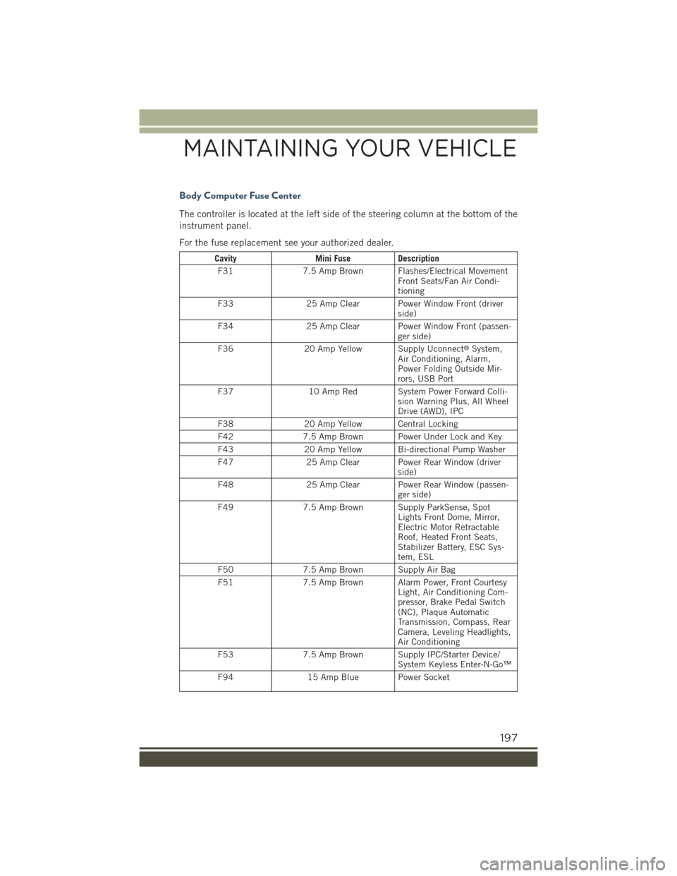
Body Computer Fuse Center
The controller is located at the left side of the steering column at the bottom of the
instrument panel.
For the fuse replacement see your authorized dealer.
CavityMini FuseDescription
F317.5 Amp Brown Flashes/Electrical MovementFront Seats/Fan Air Condi-tioning
F3325 Amp Clear Power Window Front (driverside)
F3425 Amp Clear Power Window Front (passen-ger side)
F3620 Amp Yellow Supply Uconnect®System,Air Conditioning, Alarm,Power Folding Outside Mir-rors, USB Port
F3710 Amp Red System Power Forward Colli-sion Warning Plus, All WheelDrive (AWD), IPC
F3820 Amp Yellow Central Locking
F427.5 Amp Brown Power Under Lock and Key
F4320 Amp Yellow Bi-directional Pump Washer
F4725 Amp Clear Power Rear Window (driverside)
F4825 Amp Clear Power Rear Window (passen-ger side)
F497.5 Amp Brown Supply ParkSense, SpotLights Front Dome, Mirror,Electric Motor RetractableRoof, Heated Front Seats,Stabilizer Battery, ESC Sys-tem, ESL
F507.5 Amp Brown Supply Air Bag
F517.5 Amp Brown Alarm Power, Front CourtesyLight, Air Conditioning Com-pressor, Brake Pedal Switch(NC), Plaque AutomaticTransmission, Compass, RearCamera, Leveling Headlights,Air Conditioning
F537.5 Amp Brown Supply IPC/Starter Device/System Keyless Enter-N-Go™
F9415 Amp Blue Power Socket
MAINTAINING YOUR VEHICLE
197
Page 209 of 220
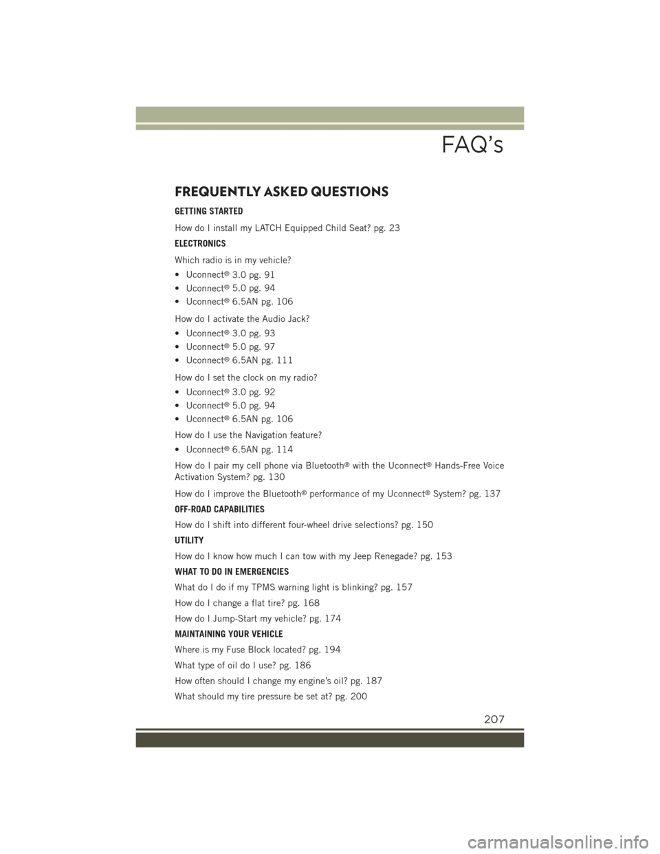
FREQUENTLY ASKED QUESTIONS
GETTING STARTED
How do I install my LATCH Equipped Child Seat? pg. 23
ELECTRONICS
Which radio is in my vehicle?
• Uconnect®3.0 pg. 91
• Uconnect®5.0 pg. 94
• Uconnect®6.5AN pg. 106
How do I activate the Audio Jack?
• Uconnect®3.0 pg. 93
• Uconnect®5.0 pg. 97
• Uconnect®6.5AN pg. 111
How do I set the clock on my radio?
• Uconnect®3.0 pg. 92
• Uconnect®5.0 pg. 94
• Uconnect®6.5AN pg. 106
How do I use the Navigation feature?
• Uconnect®6.5AN pg. 114
How do I pair my cell phone via Bluetooth®with the Uconnect®Hands-Free Voice
Activation System? pg. 130
How do I improve the Bluetooth®performance of my Uconnect®System? pg. 137
OFF-ROAD CAPABILITIES
How do I shift into different four-wheel drive selections? pg. 150
UTILITY
How do I know how much I can tow with my Jeep Renegade? pg. 153
WHAT TO DO IN EMERGENCIES
What do I do if my TPMS warning light is blinking? pg. 157
How do I change a flat tire? pg. 168
How do I Jump-Start my vehicle? pg. 174
MAINTAINING YOUR VEHICLE
Where is my Fuse Block located? pg. 194
What type of oil do I use? pg. 186
How often should I change my engine’s oil? pg. 187
What should my tire pressure be set at? pg. 200
FAQ’s
207
Page 210 of 220
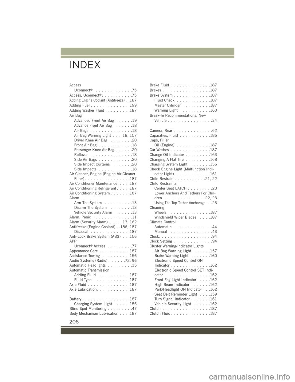
Access
Uconnect®.............75
Access, Uconnect®...........75
Adding Engine Coolant (Antifreeze)..187
Adding Fuel..............199
Adding Washer Fluid.........187
Air Bag
Advanced Front Air Bag . . . . . .19
Advance Front Air Bag . . . . . .18
Air Bags . . . . . . . . . . . . . . .18Air Bag Warning Light . . . .18, 157Driver Knee Air Bag........20Front Air Bag . . . . . . . . . . . .18Passenger Knee Air Bag......20Rollover...............18Side Air Bags . . . . . . . . . . . .20Side Impact Curtains.......20Side Impacts . . . . . . . . . . . .18Air Cleaner, Engine (Engine Air CleanerFilter)................187Air Conditioner Maintenance....187Air Conditioning Refrigerant.....187Air Conditioning System.......187AlarmArm The System..........13Disarm The System........13Vehicle Security Alarm......13Alarm, Panic..............11Alarm (Security Alarm).....13,162Antifreeze (Engine Coolant) . .186, 187Disposal . . . . . . . . . . . . . .187Anti-Lock Brake System (ABS) . . .156APPUconnect®Access . . . . . . . . .77Appearance Care...........187Assistance Towing..........156Audio Systems (Radio)......72,96Automatic Headlights.........35Automatic TransmissionAdding Fluid...........187Fluid Type . . . . . . . . . . . .187Axle Fluid . . . . . . . . . . . . . . .187Axle Lubrication............187
Battery.................187Charging System Light.....156Blind Spot Monitoring.........47Body Mechanism Lubrication....187
Brake Fluid . . . . . . . . . . . . . .187
Brakes . . . . . . . . . . . . . . . . .187
Brake System.............187
Fluid Check . . . . . . . . . . . .187
Master Cylinder.........187
Warning Light..........160
Break-In Recommendations, New
Vehicle................34
Camera, Rear..............62Capacities, Fluid...........186Caps, FillerOil (Engine)............187Car Washes . . . . . . . . . . . . . .187Change Oil Indicator.........163Changing A Flat Tire . . . . . . . . .168Charging System Light........156Check Engine Light (Malfunction Indi-cator Light).............161Child Restraint...........21,22Child RestraintsCenter Seat LATCH . . . . . . . . .23Lower Anchors And Tethers For Chil-dren . . . . . . . . . . . . . .22, 23
Using The Top Tether Anchorage..23CleaningWheels..............187Windshield Wiper Blades....187Climate ControlAutomatic..............44Manual . . . . . . . . . . . . . . .43Clock...................94Clock Setting..............94Cluster Warning/Indicator LightsAir Bag Warning Light . . . . . .157Brake Warning Light.......160Electronic Speed Control ONIndicator..............162Electronic Speed Control SET Indi-cator................162Front Fog Light Indicator....162High Beam Indicator......162Park/Headlight ON Indicator . .162Seat Belt Reminder Light . . . .159Turn Signal Indicator......161Vehicle Security Light......162Clutch . . . . . . . . . . . . . . . . .187Clutch Fluid . . . . . . . . . . . . . .187
INDEX
208