display JEEP RENEGADE 2015 1.G User Guide
[x] Cancel search | Manufacturer: JEEP, Model Year: 2015, Model line: RENEGADE, Model: JEEP RENEGADE 2015 1.GPages: 220, PDF Size: 34.11 MB
Page 3 of 220
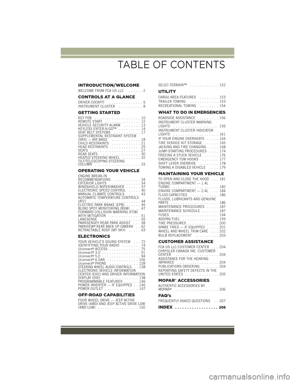
INTRODUCTION/WELCOME
WELCOME FROM FCA US LLC...... 2
CONTROLS AT A GLANCE
DRIVER COCKPIT.............. 6INSTRUMENT CLUSTER.......... 8
GETTING STARTED
KEY FOB . . . . . . . . . . . . . . . . . . . 10REMOTE START............... 12VEHICLE SECURITY ALARM....... 13KEYLESS ENTER-N-GO™......... 14SEAT BELT SYSTEMS........... 17SUPPLEMENTAL RESTRAINT SYSTEM(SRS) — AIR BAGS............ 18CHILD RESTRAINTS............ 21HEAD RESTRAINTS............. 25SEATS . . . . . . . . . . . . . . . . . . . . . 27REAR SEATS................ 30HEATED STEERING WHEEL........ 32TILT/TELESCOPING STEERINGCOLUMN................... 33
OPERATING YOUR VEHICLE
ENGINE BREAK-INRECOMMENDATIONS........... 34EXTERIOR LIGHTS............. 34WINDSHIELD WIPER/WASHER...... 37ELECTRONIC SPEED CONTROL..... 40MANUAL CLIMATE CONTROLS...... 43AUTOMATIC TEMPERATURE CONTROLS(ATC) . . . . . . . . . . . . . . . . . . . . . . 44ELECTRIC PARK BRAKE (EPB)...... 45BLIND SPOT MONITORING (BSM).... 47FORWARD COLLISION WARNING (FCW)WITH MITIGATION . . . . . . . . . . . . . 51LANESENSE................. 55PA R K S E N S E®REAR PARK ASSIST . . . 58PARKVIEW®REAR BACK UP CAMERA.. 62RETRACTABLE ROOF (MY SKY)..... 63
ELECTRONICS
YOUR VEHICLE'S SOUND SYSTEM . . . 72IDENTIFYING YOUR RADIO........ 74Uconnect®ACCESS............. 75Uconnect®3.0 . . . . . . . . . . . . . . . . 91Uconnect®5.0 . . . . . . . . . . . . . . . . 94Uconnect®6.5AN . . . . . . . . . . . . . 106Uconnect®PHONE............ 128STEERING WHEEL AUDIO CONTROLS.. 138ELECTRONIC VEHICLE INFORMATIONCENTER (EVIC) AND DRIVER INFORMATIONDISPLAY (DID)............... 138PROGRAMMABLE FEATURES...... 146POWER INVERTER — IF EQUIPPED . . 146POWER OUTLET.............. 147
OFF-ROAD CAPABILITIES
FOUR WHEEL DRIVE — JEEP ACTIVEDRIVE (4WD) AND JEEP ACTIVE DRIVE LOW(4WD LOW)................. 150
SELEC-TERRAIN™............ 152
UTILITY
CARGO AREA FEATURES........ 153TRAILER TOWING............ 153RECREATIONAL TOWING........ 154
WHAT TO DO IN EMERGENCIES
ROADSIDE ASSISTANCE......... 156INSTRUMENT CLUSTER WARNINGLIGHTS................... 156INSTRUMENT CLUSTER INDICATORLIGHTS................... 161IF YOUR ENGINE OVERHEATS..... 164TIRE SERVICE KIT STORAGE...... 165JACKING AND TIRE CHANGING.... 168JUMP-STARTING PROCEDURES.... 174FREEING A STUCK VEHICLE...... 176EMERGENCY TOW HOOKS....... 177SHIFT LEVER OVERRIDE........ 178TOWING A DISABLED VEHICLE.... 179
MAINTAINING YOUR VEHICLE
TO OPEN AND CLOSE THE HOOD . . . 181ENGINE COMPARTMENT — 1.4LTURBO................... 182ENGINE COMPARTMENT — 2.4L . . . 184FLUID CAPACITIES............ 186FLUIDS, LUBRICANTS AND GENUINEPA RT S . . . . . . . . . . . . . . . . . . . . 1 8 6MAINTENANCE PROCEDURES..... 187MAINTENANCE SCHEDULE....... 187FUSES.................... 194ADDING FUEL............... 199TIRE PRESSURES............. 200SPARE TIRES — IF EQUIPPED..... 201WHEEL AND WHEEL TRIM CARE . . . 202BULB REPLACEMENT.......... 203
CUSTOMER ASSISTANCE
FCA US LLC CUSTOMER CENTER . . . 204CHRYSLER CANADA INC. CUSTOMERCENTER.................. 204ASSISTANCE FOR THE HEARINGIMPAIRED . . . . . . . . . . . . . . . . . 204PUBLICATIONS ORDERING....... 204REPORTING SAFETY DEFECTS IN THEUNITED STATES . . . . . . . . . . . . . . 205
MOPAR® ACCESSORIES
AUTHENTIC ACCESSORIES BYMOPAR®.................. 206
FAQ ’ s
FREQUENTLY ASKED QUESTIONS . . 207
INDEX.................. 208
TABLE OF CONTENTS
Page 8 of 220
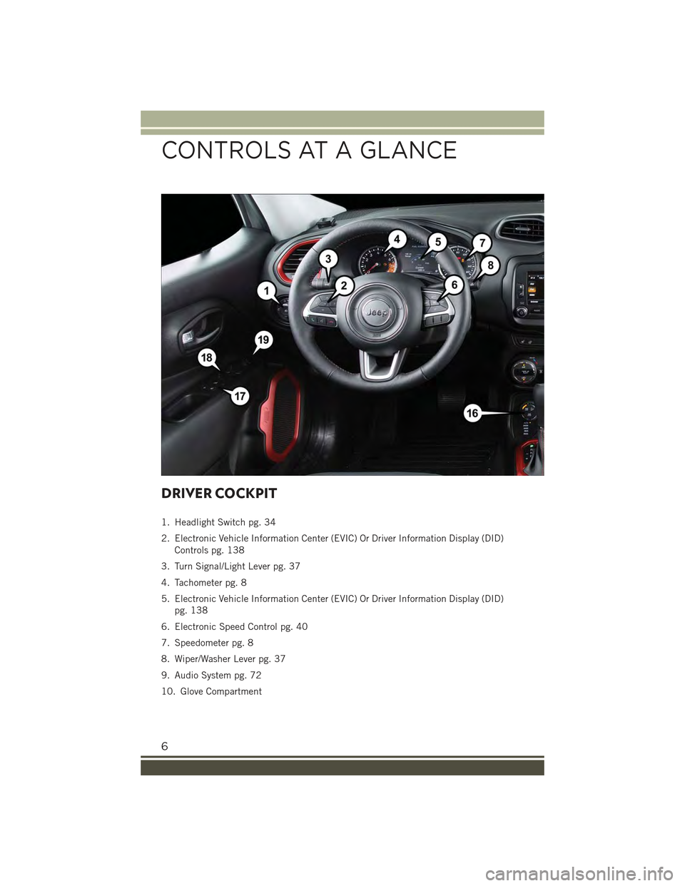
DRIVER COCKPIT
1. Headlight Switch pg. 34
2. Electronic Vehicle Information Center (EVIC) Or Driver Information Display (DID)
Controls pg. 138
3. Turn Signal/Light Lever pg. 37
4. Tachometer pg. 8
5. Electronic Vehicle Information Center (EVIC) Or Driver Information Display (DID)
pg. 138
6. Electronic Speed Control pg. 40
7. Speedometer pg. 8
8. Wiper/Washer Lever pg. 37
9. Audio System pg. 72
10. Glove Compartment
CONTROLS AT A GLANCE
6
Page 10 of 220
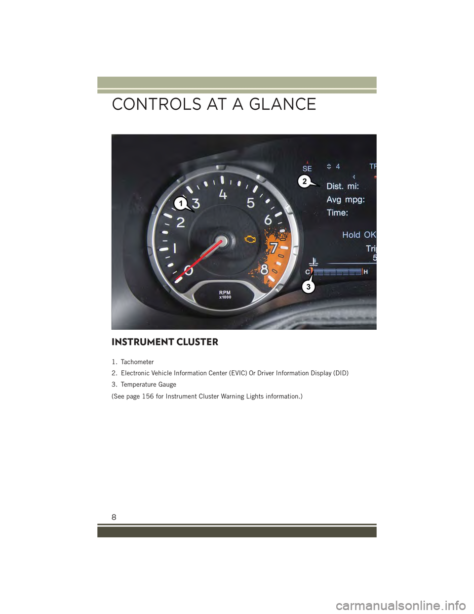
INSTRUMENT CLUSTER
1. Tachometer
2. Electronic Vehicle Information Center (EVIC) Or Driver Information Display (DID)
3. Temperature Gauge
(See page 156 for Instrument Cluster Warning Lights information.)
CONTROLS AT A GLANCE
8
Page 31 of 220
Power Lumbar Adjustment
Push the switch forward or rearward to increase or decrease the lumbar support. Push
the switch upward or downward to raise or lower the lumbar support.
Heated Seats — If Equipped
The heated seat switches are located on the instrument panel.
You can choose between two heating levels:
• Push the heated seat buttononce to turn the HI setting ON.
• Push the heated seat buttona second time to turn the LO setting ON.
• Push the heated seat buttona third time to turn the heating elements OFF.
If the HI-level setting is selected, the system will automatically switch to LO-level
after approximately 145 minutes of continuous operation. At that time, the display
will change from HI to LO, indicating the change. The LO-level setting will turn OFF
automatically after approximately 60 minutes.
NOTE:
The engine must be running for the heated seats to operate.
Vehicles Equipped With Remote Start
Vehicles equipped with Remote Start, the heated seats can be programed to come on
during a Remote Start.
This feature can be programmed through the Uconnect®system. Refer to
“Uconnect®Settings” in “Multimedia” in your Owner’s Manual on the DVD for
further information.
WARNING!
• Persons who are unable to feel pain to the skin because of advanced age,
chronic illness, diabetes, spinal cord injury, medication, alcohol use, exhaus-
tion or other physical condition must exercise care when using the seat heater.
It may cause burns even at low temperatures, especially if used for long periods
of time.
• Do not place anything on the seat or seatback that insulates against heat, such
as a blanket or cushion. This may cause the seat heater to overheat. Sitting in
a seat that has been overheated could cause serious burns due to the increased
surface temperature of the seat.
GETTING STARTED
29
Page 37 of 220
Automatic Lighting — If Equipped
Light Sensor
The light sensor is equipped with an infrared LED, located on the windshield. It
detects changes in light intensity outside the vehicle, based on the sensitivity of light
set by using the Menu on the display or on the Uconnect®system.
The higher the sensitivity, the lesser the amount of external light required for
controlling the lighting.
Automatic Headlights
Turn the headlight switch to the AUTO position.
When the automatic headlights are enabled, the headlight time delay is active. After
the ignition switch is placed in the STOP/OFF position, the headlights will automati-
cally turn off after approximately 90 seconds depending on the settings of the
feature.
The timing of the headlights is adjustable between 0, 30, 60 and 90 seconds.
NOTE:
The engine must be running before the headlights will come on in the automatic
mode.
Daytime Running Lights (DRL) — If Equipped
The Daytime Running Lights (DRLs) will turn on when the engine is started and
remain on unless the headlights are turned on, the electronic parking brake is
applied, or the engine is shut off.
The DRLs will be disabled during turn signal operation and resume operation when
the turn signal operation has ended.
Front Fog Lights — If Equipped
The front fog light switch is built into the headlight switch.
To activate the front fog lights, turn on the parking lights or the low beam headlights
and push the headlight switch. To turn off the front fog lights, push the headlight
switch a second time or turn off the headlight switch.
An indicator light in the instrument cluster illuminates when the fog lights are turned
on.
NOTE:
The fog lights will operate with the low beam headlights or parking lights on.
Selecting the high beam headlights will turn off the fog lights.
Parking Lights
Rotate the headlight switch to the first position to turn on the parking lights. The
parking light indicator in the cluster will illuminate.
OPERATING YOUR VEHICLE
35
Page 42 of 220
ELECTRONIC SPEED CONTROL
When engaged, the Electronic Speed Control takes over accelerator operations at
speeds greater than 25 mph (40 km/h).
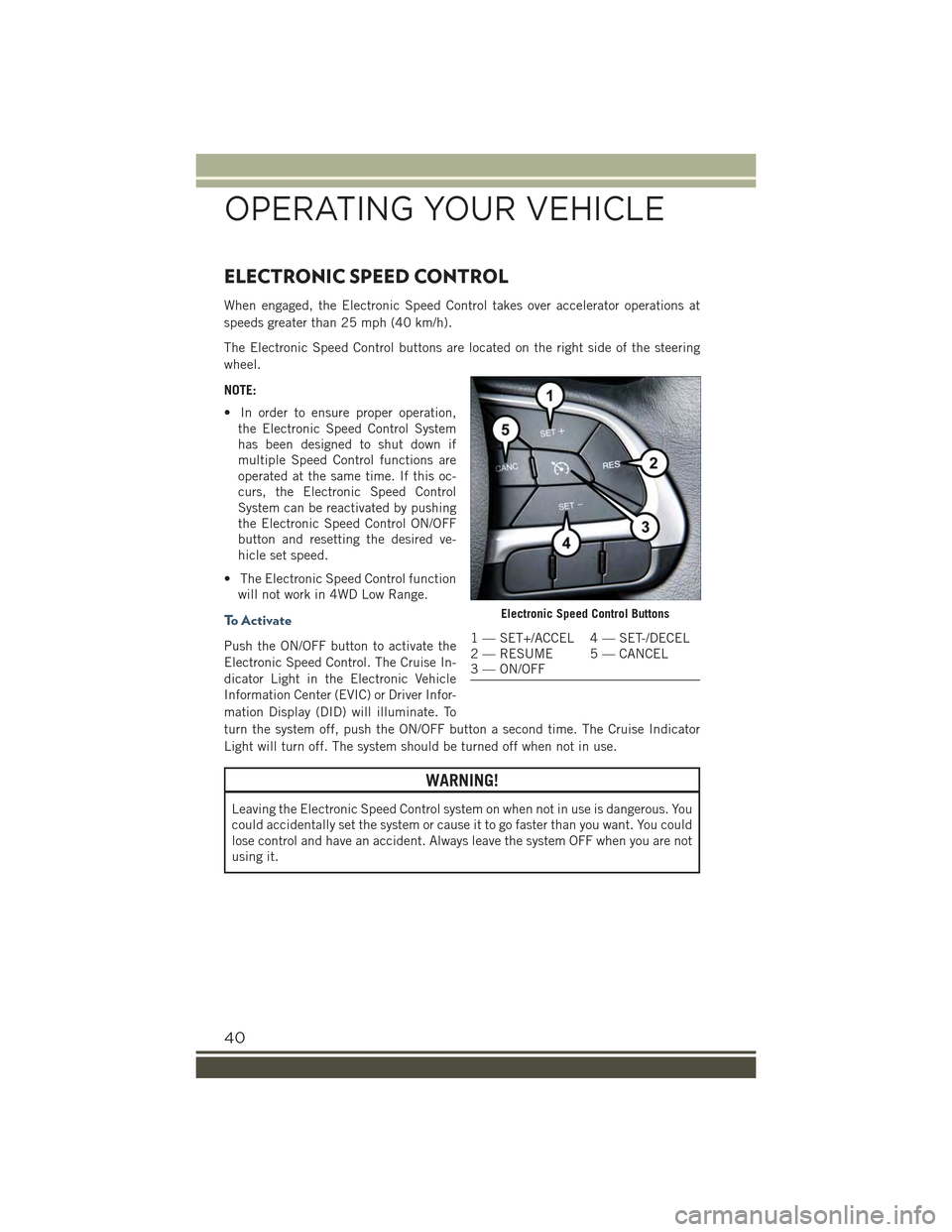
The Electronic Speed Control buttons are located on the right side of the steering
wheel.
NOTE:
• In order to ensure proper operation,
the Electronic Speed Control System
has been designed to shut down if
multiple Speed Control functions are
operated at the same time. If this oc-
curs, the Electronic Speed Control
System can be reactivated by pushing
the Electronic Speed Control ON/OFF
button and resetting the desired ve-
hicle set speed.
• The Electronic Speed Control function
will not work in 4WD Low Range.
To A c t i v a t e
Push the ON/OFF button to activate the
Electronic Speed Control. The Cruise In-
dicator Light in the Electronic Vehicle
Information Center (EVIC) or Driver Infor-
mation Display (DID) will illuminate. To
turn the system off, push the ON/OFF button a second time. The Cruise Indicator
Light will turn off. The system should be turned off when not in use.
WARNING!
Leaving the Electronic Speed Control system on when not in use is dangerous. You
could accidentally set the system or cause it to go faster than you want. You could
lose control and have an accident. Always leave the system OFF when you are not
using it.
Electronic Speed Control Buttons
1 — SET+/ACCEL 4 — SET-/DECEL2 — RESUME 5 — CANCEL3 — ON/OFF
OPERATING YOUR VEHICLE
40
Page 46 of 220
AUTOMATIC TEMPERATURE CONTROLS (ATC)
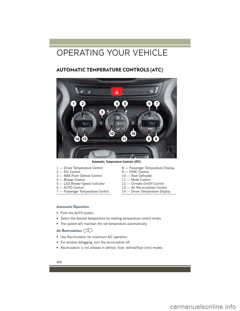
Automatic Operation
• Push the AUTO button.
• Select the desired temperature by rotating temperature control knobs.
• The system will maintain the set temperature automatically.
Air Recirculation
• Use Recirculation for maximum A/C operation.
• For window defogging, turn the recirculation off.
• Recirculation is not allowed in defrost, floor, defrost/floor (mix) modes.
Automatic Temperature Controls (ATC)
1 — Driver Temperature Control2 — A/C Control3 — MAX Front Defrost Control4 — Blower Control5 — LED Blower Speed Indicator6 — AUTO Control7 — Passenger Temperature Control
8 — Passenger Temperature Display9 — SYNC Control10 — Rear Defroster11 — Mode Control12 — Climate On/Off Control13 — Air Recirculation Control14 — Driver Temperature Display
OPERATING YOUR VEHICLE
44
Page 52 of 220
Mode Of Operation
Three selectable modes of operation are available in the Uconnect®System. Refer to
“Uconnect®Settings” in “Multimedia” in your Owner’s Manual on the DVD for
further information.
Blind Spot Alert Lights Only
When operating in Blind Spot Alert mode, the BSM system will provide a visual alert
in the appropriate side view mirror based on a detected object. However, when the
system is operating in Rear Cross Path (RCP) mode, the system will respond with
both visual and audible alerts when a detected object is present. Whenever an
audible alert is requested, the radio is muted.
Blind Spot Alert Lights/Chime
When operating in Blind Spot Alert Lights/Chime mode, the BSM system will provide a
visual alert in the appropriate side view mirror based on a detected object. If the turn
signal is then activated, and it corresponds to an alert present on that side of the vehicle,
an audible chime will also be sounded. Whenever a turn signal and detected object are
present on the same side at the same time, both the visual and audible alerts will be
issued. In addition to the audible alert, the radio (if on) will also be muted.
NOTE:
Whenever an audible alert is requested by the BSM system, the radio is also muted.
When the system is in RCP, the system will respond with both visual and audiblealerts when a detected object is present. Whenever an audible alert is requested, theradio is also muted. Turn/hazard signal status is ignored; the RCP state alwaysrequests the chime.
Blind Spot Alert Off
When the BSM system is turned off, there will be no visual or audible alerts from
either the BSM or RCP systems.
NOTE:
The BSM system will store the current operating mode when the vehicle is shut off.
Each time the vehicle is started the previously stored mode will be recalled and used.
Blind Spot Monitoring Fault Warnings
Sensor Blinded
In the case of a sensor blinded:
• BSM Mirror Warning Lights are turned on continuously.
• A chime will turn on.
• A instrument cluster message will display“Blind Spot Monitoring Unavailable - Wipe
Rear Bumper Corners.”
NOTE:
The rear bumper must be clean and free of any obstructing debris.
OPERATING YOUR VEHICLE
50
Page 53 of 220
System Not Available
In the case of the system being temporary unavailable:
• BSM Mirror Warning Lights are turned on continuously.
• A chime will turn on.
• A instrument cluster message will display“Blind Spot Monitoring Temporary
Unavailable.”
In the case of the system being completely unavailable:
• A chime will turn on.
• A instrument cluster message will display“Blind Spot Monitoring Unavailable -
Service Required.”
NOTE:
Vehicle must be taken to the nearest authorized dealer for service.
FORWARD COLLISION WARNING (FCW) WITH
MITIGATION
Forward Collision Warning (FCW) With Mitigation Operation
The Forward Collision Warning (FCW) system with mitigation provides the driver with
audible warnings, visual warnings (within the EVIC/DID), and may apply a brake jerk
to warn the driver when it detects a potential frontal collision. The warnings and
limited braking are intended to provide the driver with enough time to react, avoid or
mitigate the potential collision.
NOTE:
FCW monitors the information from the forward looking sensors as well as the
Electronic Brake Controller (EBC), to calculate the probability of a forward colli-
sion. When the system determines that a forward collision is probable, the driver
will be provided with audible and visual warnings and may provide a brake jerk
warning.
If the driver does not take action based upon these progressive warnings, then the
system will provide a limited level of active braking to help slow the vehicle and
mitigate the potential forward collision. If the driver reacts to the warnings by braking
and the system determines that the driver intends to avoid the collision by braking
but has not applied sufficient brake force, the system will compensate and provide
additional brake force as required.
Vehicles With A Manual Transmission: After the end of the intervention of automatic
braking, the engine could stall, unless the driver can depress the clutch pedal.
Vehicles With Automatic Transmission: After the end of the intervention of automatic
braking, the transmission may remain in last gear stored: therefore the car could
lurch forward, once the brakes release a few seconds later.
OPERATING YOUR VEHICLE
51
Page 55 of 220
• Changing the Active Braking to “Off” prevents the system from providing limited
active braking, or additional brake support if the driver is not braking adequately
in the event of a potential frontal collision, but maintains the audible and visual
warnings.
• Changing the status of the system is only possible with the vehicle at a complete
stop.
NOTE:
The FCW system state is not kept in memory from one key cycle to the next. If the
system is turned OFF, it will turn On when the vehicle is restarted.
Changing FCW And Active Braking Status
By changing the settings on the menu of the Uconnect®system, you can change the
sensitivity of the system by choosing one of the following three options: "Near",
"Medium" or "Far".
The default option is "Medium". This setting provides that the system notify the driver
of a possible accident with the vehicle ahead of it when the latter is at a standard
distance, intermediate between the other two possible settings.
By setting the sensitivity of the system to "Far", the system will warn the driver of a
possible accident with the vehicle in front when the latter is at a greater distance,
giving you the chance to act on the brakes in a more limited and gradual. This setting
gives the driver the maximum possible time of reaction to prevent a possible
accident.
By changing the option to "Near", the system will warn the driver of a possible
accident with the vehicle ahead of it when the latter is a reduced distance. This
setting offers a reaction time to the driver lower than the settings "Medium" and "Far",
in the case of a potential accident, while a more dynamic driving of the car.
The setting of the sensitivity of the system is maintained in memory when the engine
is switched off.
FCW Limited Warning
If the EVIC/DID displays “FCW Limited Functionality” or “FCW Limited Functionality
Clean Front Windshield” momentarily, there may be a condition that limits FCW
functionality. Although the vehicle is still drivable under normal conditions, the
active braking may not be fully available. Once the condition that limited the system
performance is no longer present, the system will return to its full performance state.
If the problem persists, see your authorized dealer.
Service FCW Warning
If the system turns off, and the EVIC/DID displays:
• FCW Unavailable Service Required
This indicates there is an internal system fault. Although the vehicle is still drivable
under normal conditions, have the system checked by an authorized dealer.
OPERATING YOUR VEHICLE
53