warning lights JEEP RENEGADE 2023 User Guide
[x] Cancel search | Manufacturer: JEEP, Model Year: 2023, Model line: RENEGADE, Model: JEEP RENEGADE 2023Pages: 364, PDF Size: 18.65 MB
Page 69 of 364

GETTING TO KNOW YOUR INSTRUMENT PANEL 67
Audio
Push and release the up or down arrow
button until the Audio menu title is displayed in the
instr u
ment cluster display.
Stored Messages
Push and release the up or down arrow
button until the Messages Menu Icon is highlighted
in th e
instrument cluster display. This feature
shows the number of stored warning messages.
Pushing the left
or right arrow button will
all ow
you to scroll through the stored messages.
Screen Setup
This menu item allows you to change the position
of the information on the display.
Display Gears (Vehicles With Reconfigurable
Multi-
Functional Display And Automatic
Transmission)
By selecting this item, you can select the display
mode, t
he particulars relating to the automatic
transmission, and choose between the following
options:
“Single digit”
The right side of the display will show the letter
concer n
ing the automatic transmission gear
selector (P,R,N or D) position. After approxi -
mately two seconds, the letter will be displayed
in a c
entral position.
“Full PRND”
The letters PRND will display on the right side,
the p o
sition assumed by the gear selector will
be highlighted in the display. During the opera -
tion in sequential mode (“AutoStick”), in place
of the
letter D, the gear will be will be displayed.
In The Upper Left/Top Right
The information relating to the following can be
displ a
yed:
External temperature
Ignition Button — If Equipped
Compass — If Equipped
Date (Month/Day)
Time (Hours/Minutes)
In the central area of the display, you can view all
of t
h e
information listed above as well as the
following:
Compass — If Equipped
Speed Display — If Equipped
Date (Day/Month/Year)
Time
Compass — If Equipped
Ignition Button — If Equipped
External Temp — If equipped
Menu Item
Distance Traveled A (Trip A)
Distance Traveled B (Trip B)
Restore Default Settings
Selecting this item, and you can reset and restore
t he de
fault settings.
Settings
This menu item allows you to change the settings
for the following:
Display
Units
Clock and Date
Security
Safety and Assistance
Lights
Doors and Locks
NOTE:
Some items may be displayed and managed
throug h
the Uconnect system.
Vehicles Equipped With Multi-functional Display
Reconfi
gurable:
The following menu/submenu items are available
in the
cluster display.
3
Page 70 of 364

68 GETTING TO KNOW YOUR INSTRUMENT PANEL
“Vehicle Shut Off (If Equipped)”
By selecting the item “Vehicle Shut Off”, you can
turn of
f the engine from the instrument cluster.
This feature is available in the event of an ignition
switch failure, and will display instructions for
turning off the engine via the instrument cluster
display controls.
“Display”
By selecting the “Display,” you can access the
follow i
ng setting:
Language : allows you to select the language in
which to display the information/warnings.
“Units Of Measure”
By selecting the item “Units of Measure,” you can
selec t
the unit of measure to use for displaying
various magnitudes.
Possible options are:
US
Metric
Custom
“Clock & Date”
By selecting the item, “Clock & Date” you can
a djust
the clock.
Possible options are:
Set Time: adjust hours/minutes
Set Format: adjust the time format “12h”
(12 hours) or “24h” (24 hours)
Set Date: adjust day/month/year
“Security”
By selecting the item “Security,” you can make the
f ollowi
ng adjustments:
Speed Warning:
Set the vehicle speed limit, which the driver is
notifi e
d through a visual and acoustic signaling
(display of a message and a symbol on the
display).
When the speed warning is set, the icon should
remain
visualized for the same duration time of
the pop-up. If the driver exceeded the set speed,
the icon should remain for however long the
vehicle is over the set speed.
Driver may also turn the Speed Warning “OFF”
should
you choose not to use this feature.
Seat Belt Reminder:
This function is only viewable when the Seat Belt
Remin d
er (SBR) system is active.
Hill Start Assist:
Activation/Deactivation of the Hill Start Assist
syste m
.
Passenger Air Bag — If Equipped
Front passenger air bag may be enabled or
disab l
ed. “Lights”
By selecting the item “Lights,” you can make the
followi
n
g adjustments:
Headlight Off Delay: set the delay for headlight
shutoff after engine shutoff
Headlight Sensitivity: adjust the sensitivity of
headlight brightness
Daytime Running Lights: activate/deactivate
the daytime running lights
Cornering lights: activate/deactivate the
cornering lights (If Equipped)
Interior Ambient lights: adjust the level of inte-
rior ambient lights
Greeting Lights: activate / deactivate greeting
lights
“Doors & Locks”
By selecting the item “Doors & Locks,” you can
make t
he following adjustments:
Auto Door Lock: activate/deactivate the auto -
matic locking of the doors with the vehicle
m ov i
n g
Auto Unlock On Exit: automatic unlocking of the
doors when exiting the vehicle
Flash Light with Lock: activate the direction indi
-
cators when closing the doors
Page 71 of 364

GETTING TO KNOW YOUR INSTRUMENT PANEL 69
Sound Horn With Lock: activate/deactivate the
horn when pushing the LOCK button on the key
fob. The options are “Off,” “First Press,” and
“Second Press”
Horn With Remote Start: activate/deactivate
the horn at the Remote Starting of the engine
with the key fob
Remote Door Unlock: allows you to open the
driver door only on the first push of the UNLOCK
button on the key fob
“Compass”
By selecting the item “Compass” you can make the
f ollowi
ng adjustments:
Compass Calibration
Compass Variance
TRIP COMPUTER
The Trip computer is used to display information on
car operation when the key is turned to the RUN
position.
This function allows you to define two separate
trips
called “Trip A” and “Trip B” where the car's
“complete trips” are monitored in an independent
manner.
Both trips can be reset (reset - start of a new trip).
To perf
orm a reset, push and hold the OK button on
the steering wheel controls. “Trip A” and “Trip B” are used to display the figures
relat
i
ng to:
Distance Traveled
Average Consumption
Travel Time (driving time)
Quantities Displayed
Distance Traveled
Indicates the distance traveled by the start of
the new trip.
Average Consumption
Represents the average fuel consumption since
the start of the new trip.
Travel Time
Elapsed time since the start of the new trip.
OK Button
Short Push Of The Button: display of various
p arame
ters.
Long Push Of The Button: reset quantities and
begin
a new trip.
New trip
Starts after reset:
“Manual” by pushing the OK button.
“Automatic” when the “distance” reaches the
value of 62140 (99999.9 km) or when the “time
travel” reaches the value of 999.59
(999 hours and 59 minutes).
After each disconnection and reconnection of
the battery.
WARNING/INDICATOR LIGHTS AND
MESSAGES
The warning/indicator light switches on in the
instrument panel together with a dedicated
message and/or acoustic signal when applicable.
These indications are indicative and precautionary
and as such must not be considered as exhaustive
and/or alternative to the information contained in
the Owner Manual, which you are advised to read
carefully in all cases. Always refer to the
information in this chapter in the event of a failure
indication.
All active telltales will display first, if applicable.
The sy
stem check menu may appear different
based upon equipment options and current vehicle
status. Some telltales are optional and may not
appear.
The following warning lamps and indicators will
alert
you to a vehicle condition that may become
serious. Some lamps will illuminate when you start
your vehicle to make sure they work. If any lamps
remain on after starting your vehicle, refer to the
respective system warning lamp for further
information.
3
Page 72 of 364
70 GETTING TO KNOW YOUR INSTRUMENT PANEL
RED WARNING LIGHTS
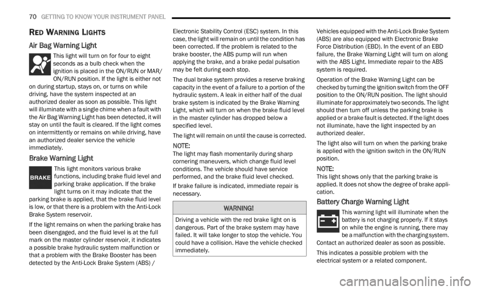
Air Bag Warning Light
This light will turn on for four to eight
seconds as a bulb check when the
i
g n
it
i
on is placed in the ON/RUN or MAR/
ON/RUN position. If the light is either not
on during startup, stays on, or turns on while
driving, have the system inspected at an
authorized dealer as soon as possible. This light
will illuminate with a single chime when a fault with
the Air Bag Warning Light has been detected, it will
stay on until the fault is cleared. If the light comes
on intermittently or remains on while driving, have
an authorized dealer service the vehicle
immediately.
Brake Warning Light
This light monitors various brake
functions, including brake fluid level and
parki n
g brake application. If the brake
light turns on it may indicate that the
parking brake is applied, that the brake fluid level
is low, or that there is a problem with the Anti-Lock
Brake System reservoir.
If the light remains on when the parking brake has
been d
isengaged, and the fluid level is at the full
mark on the master cylinder reservoir, it indicates
a possible brake hydraulic system malfunction or
that a problem with the Brake Booster has been
detected by the Anti-Lock Brake System (ABS) / Electronic Stability Control (ESC) system. In this
case, the light will remain on until the condition has
been corrected. If the problem is related to the
brake booster, the ABS pump will run when
applying the brake, and a brake pedal pulsation
may be felt during each stop.
The dual brake system provides a reserve braking
capac
i
ty in the event of a failure to a portion of the
hydraulic system. A leak in either half of the dual
brake system is indicated by the Brake Warning
Light, which will turn on when the brake fluid level
in the master cylinder has dropped below a
specified level.
The light will remain on until the cause is corrected.
NOTE:
The light may flash momentarily during sharp
corner i
ng maneuvers, which change fluid level
conditions. The vehicle should have service
performed, and the brake fluid level checked.
If brake failure is indicated, immediate repair is
necess
ary. Vehicles equipped with the Anti-Lock Brake System
(ABS)
are also equipped with Electronic Brake
Force Distribution (EBD). In the event of an EBD
failure, the Brake Warning Light will turn on along
with the ABS Light. Immediate repair to the ABS
system is required.
Operation of the Brake Warning Light can be
check e
d by turning the ignition switch from the OFF
position to the ON/RUN position. The light should
illuminate for approximately two seconds. The light
should then turn off unless the parking brake is
applied or a brake fault is detected. If the light does
not illuminate, have the light inspected by an
authorized dealer.
The light also will turn on when the parking brake
is ap p
lied with the ignition switch in the ON/RUN
position.
NOTE:
This light shows only that the parking brake is
appli e
d. It does not show the degree of brake appli -
cation.
Battery Charge Warning Light
This warning light will illuminate when the
battery is not charging properly. If it stays
on wh i
le the engine is running, there may
be a malfunction with the charging system.
Contact an authorized dealer as soon as possible.
This indicates a possible problem with the
electr
ical system or a related component.
WARNING!
Driving a vehicle with the red brake light on is
dangerous. Part of the brake system may have
failed. It will take longer to stop the vehicle. You
could have a collision. Have the vehicle checked
immediately.
Page 74 of 364
72 GETTING TO KNOW YOUR INSTRUMENT PANEL
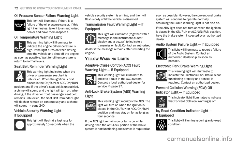
Oil Pressure Sensor Failure Warning Light
This light will illuminate if there is a
failure of the oil pressure sensor. If this
light
illuminates, take it to an authorized
dealer and have them inspect it.
Oil Temperature Warning Light
This warning light will illuminate to
indicate the engine oil temperature is
high.
If the light turns on while driving,
stop the vehicle and shut off the engine
as soon as possible. Wait for oil temperature to
return to normal levels.
Seat Belt Reminder Warning Light
This warning light indicates when the
driver or passenger seat belt is
unbuc k
led. When the ignition is first
placed in the ON/RUN or ACC/ON/RUN
position and if the driver’s seat belt is unbuckled,
a chime will sound and the light will turn on. When
driving, if the driver or front passenger seat belt
remains unbuckled, the Seat Belt Reminder Light
will flash or remain on continuously and a chime
will sound Ú page 240.
Vehicle Security Warning Light —
If Equipped
This light will flash at a fast rate for
approximately 15 seconds when the v
e h
ic
l e security system is arming, and then will
flash slowly until the vehicle is disarmed.
Transmission Fault Warning Light — If
Equipped
This light will illuminate (together with a
message in the instrument cluster
d is
p l
a
y and a buzzer) to indicate a
transmission fault. Contact an authorized
dealer if the message remains after restarting the
engine.
YELLOW WARNING LIGHTS
Adaptive Cruise Control (ACC) Fault
Warning Light — If Equipped
This warning light will illuminate to
indicate a fault in the ACC system.
C on t
a c
t
a local authorized dealer for
service Ú page 97.
Anti-Lock Brake System (ABS) Warning
Light
This warning light monitors the ABS. The
light will turn on when the ignition is
p
la
ce
d
in the ON/RUN or ACC/ON/RUN
position and may stay on for as long as
four seconds.
If the ABS light remains on or turns on while
drivin
g, then the Anti-Lock portion of the brake
system is not functioning and service is required as soon as possible. However, the conventional brake
system will continue to operate normally,
assuming the Brake Warning Light is not also on.
If the ABS light does not turn on when the ignition
is pl
a
ced in the ON/RUN or ACC/ON/RUN position,
have the brake system inspected by an authorized
dealer.
Audio System Failure Light — If Equipped
This light will illuminate to report a failure
of the Audio System. Contact an
author i
zed dealership as soon as
possible.
Electronic Park Brake Warning Light
This warning light will illuminate to
indicate the Electronic Park Brake is not
funct i
oning properly and service is
required. Contact an authorized dealer.
Forward Collision Warning (FCW) Off
Indicator Light — If Equipped
This indicator light illuminates to indicate
that Forward Collision Warning is off.
Icy Road Condition Indicator Light —
If Equipped
This light will illuminate during an icy road
condition.
Page 77 of 364
GETTING TO KNOW YOUR INSTRUMENT PANEL 75
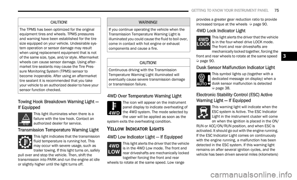
Towing Hook Breakdown Warning Light —
If Equipped
This light illuminates when there is a
failure with the tow hook. Contact an
a ut
h or
i
zed dealer for service.
Transmission Temperature Warning Light
This light indicates that the transmission
fluid temperature is running hot. This
may occ
ur with severe usage, such as
trailer towing. If this light turns on, safely
pull over and stop the vehicle. Then, shift the
transmission into PARK and run the engine at idle
or slightly higher until the light turns off.
4WD Over Temperature Warning Light
The icon will appear on the instrument
panel display to indicate overheating of
t h e
4
W
D system. The mode selected by
the user will be applied as soon as the
system exits the overheating condition.
YELLOW INDICATOR LIGHTS
4WD Low Indicator Light — If Equipped
This light alerts the driver that the vehicle
is in the 4WD Low mode. The front and
rear d
riveshafts are mechanically locked
together forcing the front and rear
wheels to rotate at the same speed. Low range provides a greater gear reduction ratio to provide
increased torque at the wheels
Ú page 90.
4WD Lock Indicator Light
This light alerts the driver that the vehicle
is in the four-wheel drive LOCK mode.
The f r
ont and rear driveshafts are
mechanically locked together, forcing the
front and rear wheels to rotate at the same speed
Ú page 90.
Dusk Sensor Malfunction Indicator Light
This symbol lights up (together with a
dedicated message on display) when a
dusk s
ensor malfunction is detected
Ú page 38.
Electronic Stability Control (ESC) Active
Warning Light — If Equipped
This warning light will indicate when the
ESC system is Active. The ESC Indicator
Light
in the instrument cluster will come
on when the ignition is placed in the ON/
RUN or ACC/ON/RUN position, and when ESC is
activated. It should go out with the engine running.
If the ESC Indicator Light comes on continuously
with the engine running, a malfunction has been
detected in the ESC system. If this warning light
remains on after several ignition cycles, and the
vehicle has been driven several miles (kilometers)
CAUTION!
The TPMS has been optimized for the original
equipment tires and wheels. TPMS pressures
and warning have been established for the tire
size equipped on your vehicle. Undesirable sys -
tem operation or sensor damage may result
w hen u
sing replacement equipment that is not
of the same size, type, and/or style. Aftermarket
wheels can cause sensor damage. Using after -
market tire sealants may cause the Tire Pres -
sure Monitoring System (TPMS) sensor to
b ecome
inoperable. After using an aftermarket
tire sealant it is recommended that you take
your vehicle to an authorized dealer to have your
sensor function checked.
WARNING!
If you continue operating the vehicle when the
Transmission Temperature Warning Light is
illuminated you could cause the fluid to boil over,
come in contact with hot engine or exhaust
components and cause a fire.
CAUTION!
Continuous driving with the Transmission
Temperature Warning Light illuminated will
eventually cause severe transmission damage
or transmission failure.
3
Page 78 of 364
76 GETTING TO KNOW YOUR INSTRUMENT PANEL
at speeds greater than 30 mph (48 km/h), see an
authori
zed dealer as soon as possible to have the
problem diagnosed and corrected.
The ESC OFF Indicator Light and the ESC Indi -
cator Light come on momentarily each time the
ignit i
on is placed in the ON/RUN or ACC/ON/
RUN position.
The ESC system will make buzzing or clicking
sounds when it is active. This is normal; the
sounds will stop when ESC becomes inactive.
This light will come on when the vehicle is in an
ESC event.
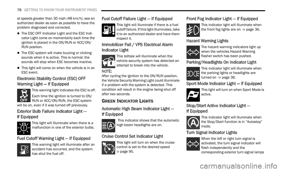
Electronic Stability Control (ESC) OFF
Warning Light — If Equipped
This warning light indicates the ESC is off.
Each time the ignition is turned to ON/
RUN or
ACC/ON/RUN, the ESC system
will be on, even if it was turned off previously.
Exterior Bulb Failure Indicator Light —
If Equipped
This light will illuminate when there is a
malfunction in one of the exterior bulbs.
Fuel Cutoff Warning Light — If Equipped
This warning light will illuminate after an
accident has occurred, and the system
has s h
ut the fuel off.
Fuel Cutoff Failure Light — If Equipped
This light will illuminate if there is a fuel
cutoff failure. If this light illuminates, take
it to a
n authorized dealer and have them
inspect it.
Immobilizer Fail / VPS Electrical Alarm
Indicator Light
This telltale will illuminate when the
vehicle security system has detected an
a tt
e m
p
t to break into the vehicle.
NOTE:
After cycling the ignition to the ON/RUN position,
the V e
hicle Security Warning Light could illuminate
if a problem with the system is detected. This
condition will result in the engine being shut off
after two seconds.
GREEN INDICATOR LIGHTS
Automatic High Beam Indicator Light —
If Equipped
This indicator shows that the automatic
high beam headlights are on.
Cruise Control Set Indicator Light
This light will turn on when the cruise
control is set to the desired speed
Ú page 95.
Front Fog Indicator Light — If Equipped
This indicator light will illuminate when
the front fog lights are on Ú page 36.
Hazard Warning Lights
The hazard warning indicators light up
when the vehicles Hazard Warning
flash e
r switch has been pushed.
Parking/Headlights On Indicator Light
This indicator light will illuminate when
the parking lights or headlights are
tu r
n e
d
on Ú page 36.
Sport Mode Indicator Light — If Equipped
This light will turn on when Sport Mode is
active.
Stop/Start Active Indicator Light —
If Equipped
This indicator light will illuminate when
the Stop/Start function is in “Autostop”
mode.
Turn Signal Indicator Lights
When the left or right turn signal is
activated, the turn signal indicator will
f la
sh
independently and the
corresponding exterior turn signal lamps
Page 79 of 364
GETTING TO KNOW YOUR INSTRUMENT PANEL 77
will flash. Turn signals can be activated when the
multifunction lever is moved down (left) or up
(right).
WHITE INDICATOR LIGHTS
Hill Descent Control (HDC) Indicator Light —
If Equipped
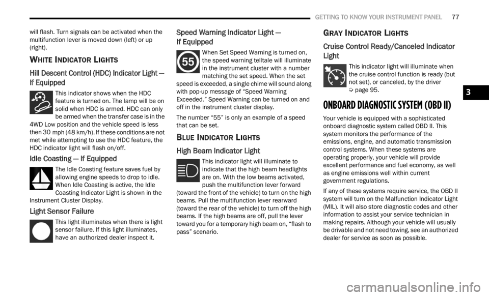
This indicator shows when the HDC
feature is turned on. The lamp will be on
solid w
hen HDC is armed. HDC can only
be armed when the transfer case is in the
4WD Low position and the vehicle speed is less
then 30 mph (48 km/h). If these conditions are not
met wh
ile attempting to use the HDC feature, the
HDC indicator light will flash on/off.
Idle Coasting — If Equipped
The Idle Coasting feature saves fuel by
allowing engine speeds to drop to idle.
W he
n
I
dle Coasting is active, the Idle
Coasting Indicator Light is shown in the
Instrument Cluster Display.
Light Sensor Failure
This light illuminates when there is light
sensor failure. If this light illuminates,
have a
n authorized dealer inspect it.
Speed Warning Indicator Light —
If Equipped
When Set Speed Warning is turned on,
the speed warning telltale will illuminate
i n
t h
e
instrument cluster with a number
matching the set speed. When the set
speed is exceeded, a single chime will sound along
with pop-up message of “Speed Warning
Exceeded.” Speed Warning can be turned on and
off in the instrument cluster display.
The number “55” is only an example of a speed
that c
an be set.
BLUE INDICATOR LIGHTS
High Beam Indicator Light
This indicator light will illuminate to
indicate that the high beam headlights
are on .
With the low beams activated,
push the multifunction lever forward
(toward the front of the vehicle) to turn on the high
beams. Pull the multifunction lever rearward
(toward the rear of the vehicle) to turn off the high
beams. If the high beams are off, pull the lever
toward you for a temporary high beam on, “flash to
pass” scenario.
GRAY INDICATOR LIGHTS
Cruise Control Ready/Canceled Indicator
Light
This indicator light will illuminate when
the cruise control function is ready (but
not se t
), or canceled, by the driver
Ú page 95.
ONBOARD DIAGNOSTIC SYSTEM (OBD II)
Your vehicle is equipped with a sophisticated
onboard diagnostic system called OBD II. This
system monitors the performance of the
emissions, engine, and automatic transmission
control systems. When these systems are
operating properly, your vehicle will provide
excellent performance and fuel economy, as well
as engine emissions well within current
government regulations.
If any of these systems require service, the OBD II
syste m
will turn on the Malfunction Indicator Light
(MIL). It will also store diagnostic codes and other
information to assist your service technician in
making repairs. Although your vehicle will usually
be drivable and not need towing, see an authorized
dealer for service as soon as possible.
3
Page 103 of 364
STARTING AND OPERATING 101
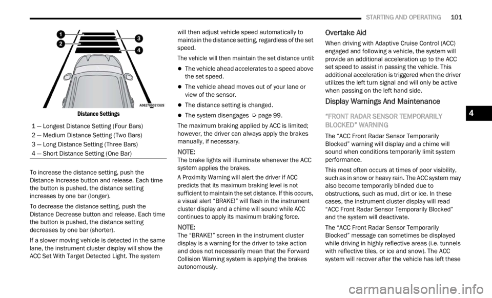
Distance Settings
To increase the distance setting, push the
Distan
ce Increase button and release. Each time
the button is pushed, the distance setting
increases by one bar (longer).
To decrease the distance setting, push the
Distan
ce Decrease button and release. Each time
the button is pushed, the distance setting
decreases by one bar (shorter).
If a slower moving vehicle is detected in the same
lane,
the instrument cluster display will show the
ACC Set With Target Detected Light. The system will then adjust vehicle speed automatically to
maintain the distance setting, regardless of the set
speed.
The vehicle will then maintain the set distance until:
The vehicle ahead accelerates to a speed above
the set speed.
The vehicle ahead moves out of your lane or
view of the sensor.
The distance setting is changed.
The system disengages
Ú page 99.
The maximum braking applied by ACC is limited;
howeve r
, the driver can always apply the brakes
manually, if necessary.
NOTE:
The brake lights will illuminate whenever the ACC
syste m
applies the brakes.
A Proximity Warning will alert the driver if ACC
predic
ts that its maximum braking level is not
sufficient to maintain the set distance. If this occurs,
a visual alert “BRAKE!” will flash in the instrument
cluster display and a chime will sound while ACC
continues to apply its maximum braking force.
NOTE:
The “BRAKE!” screen in the instrument cluster
displ a
y is a warning for the driver to take action
and does not necessarily mean that the Forward
Collision Warning system is applying the brakes
autonomously.
Overtake Aid
When driving with Adaptive Cruise Control (ACC)
engaged and following a vehicle, the system will
provide an additional acceleration up to the ACC
set speed to assist in passing the vehicle. This
additional acceleration is triggered when the driver
utilizes the left turn signal and will only be active
when passing on the left hand side.
Display Warnings And Maintenance
“FRONT RADAR SENSOR TEMPORARILY
BLOCKED” WARNING
The “ACC Front Radar Sensor Temporarily
Blocked” warning will display and a chime will
sound when conditions temporarily limit system
performance.
This most often occurs at times of poor visibility,
such a
s in snow or heavy rain. The ACC system may
also become temporarily blinded due to
obstructions, such as mud, dirt or ice. In these
cases, the instrument cluster display will read
“ACC Front Radar Sensor Temporarily Blocked”
and the system will deactivate.
The “ACC Front Radar Sensor Temporarily
Blocke d
” message can sometimes be displayed
while driving in highly reflective areas (i.e. tunnels
with reflective tiles, or ice and snow). The ACC
system will recover after the vehicle has left these
1 — Longest Distance Setting (Four Bars)
2 — Medium Distance Setting (Two Bars)
3 — Long Distance Setting (Three Bars)
4 — Short Distance Setting (One Bar)
4
Page 130 of 364
128 STARTING AND OPERATING
Towing Requirements — Trailer Lights And
Wiring (If Equipped)
Whenever you pull a trailer, regardless of the trailer
size, stoplights and turn signals on the trailer are
required for motoring safety.
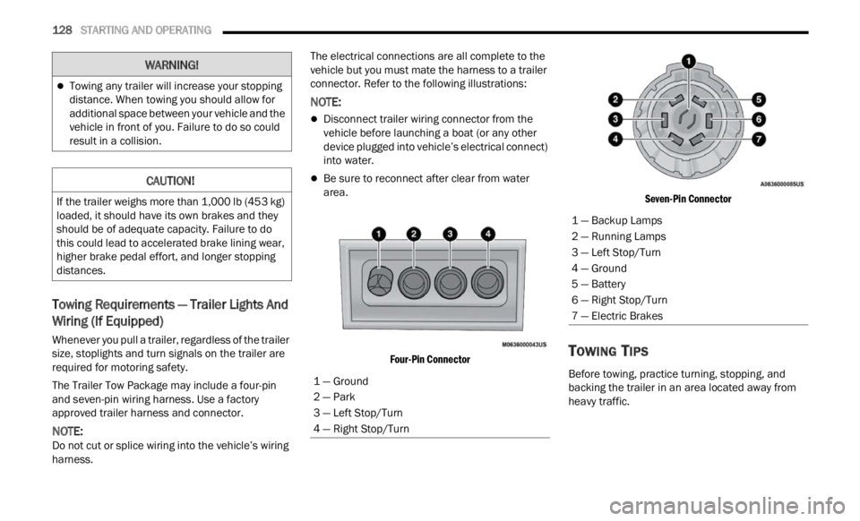
The Trailer Tow Package may include a four-pin
and s e
ven-pin wiring harness. Use a factory
approved trailer harness and connector.
NOTE:
Do not cut or splice wiring into the vehicle’s wiring
harne s
s. The electrical connections are all complete to the
vehic
l
e but you must mate the harness to a trailer
connector. Refer to the following illustrations:
NOTE:
Disconnect trailer wiring connector from the
vehicle before launching a boat (or any other
device plugged into vehicle’s electrical connect)
into water.
Be sure to reconnect after clear from water
area.
Four-Pin Connector Seven-Pin Connector
TOWING TIPS
Before towing, practice turning, stopping, and
backing the trailer in an area located away from
heavy traffic.
Towing any trailer will increase your stopping
distance. When towing you should allow for
additional space between your vehicle and the
vehicle in front of you. Failure to do so could
result in a collision.
CAUTION!
If the trailer weighs more than 1,000 lb (453 kg)
loaded, it should have its own brakes and they
should be of adequate capacity. Failure to do
this could lead to accelerated brake lining wear,
higher brake pedal effort, and longer stopping
distances.
WARNING!
1 — Ground
2 — Park
3 — Left Stop/Turn
4 — Right Stop/Turn
1 — Backup Lamps
2 — Running Lamps
3 — Left Stop/Turn
4 — Ground
5 — Battery
6 — Right Stop/Turn
7 — Electric Brakes