tire type JEEP RENEGADE 2023 Owners Manual
[x] Cancel search | Manufacturer: JEEP, Model Year: 2023, Model line: RENEGADE, Model: JEEP RENEGADE 2023Pages: 364, PDF Size: 18.65 MB
Page 8 of 364
6
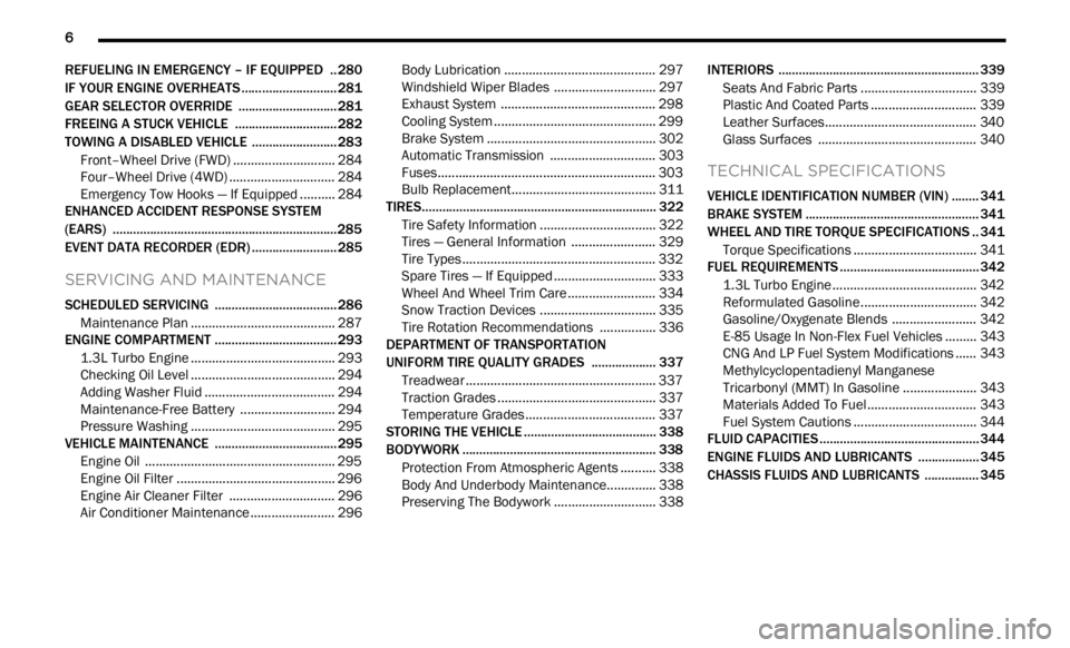
REFUELING IN EMERGENCY – IF EQUIPPED .. 280
IF YOUR ENGINE OVERHEATS ...... ...................... 281
GEAR SELECTOR OVERRIDE ...... ....................... 281
FREEING A STUCK VEHICLE ...... ........................ 282
TOWING A DISABLED VEHICLE ...... ...................283
Front–Wheel Drive (FWD) ...... ....................... 284
Four–Wheel Drive (4WD) ..... . ........................ 284
Emergency Tow Hooks — If Equipped . ..
..
. .... 284
ENHANCED ACCIDENT RESPONSE SYSTEM
(EARS) .................................................................. 285
EVEN T
DATA RECORDER (EDR) ...... ...................285
SERVICING AND MAINTENANCE
SCHEDULED SERVICING .................................... 286
Maintenance Plan ...... ................................... 287
ENGINE COMPARTMENT ..... . .............................. 293
1.3L Turbo Engine ...... ................................... 293
Checking Oil Level ..... . ................................... 294
Adding Washer Fluid . ..
..
. ............................... 294
Maintenance-Free Battery ..... . ..................... 294
Pressure Washing . ..
..
. ................................... 295
VEHICLE MAINTENANCE ..... . .............................. 295
Engine Oil ...................................................... 295
Engin e Oil Filter . ..
..
. ....................................... 296
Engine Air Cleaner Filter ..... . ........................ 296
Air Conditioner Maintenance . ..
..
. .................. 296Body Lubrication .....
.
..................................... 297
Windshield Wiper Blades ..... . ....................... 297
Exhaust System ..... . ...................................... 298
Cooling System . ..
..
. ........................................ 299
Brake System ..... . .......................................... 302
Automatic Transmission . ..
..
. ........................ 303
Fuses.............................................................. 303
Bulb
Replacement. ..
..
. ................................... 311
TIRES..................................................................... 322
Tire
Safety Information ...... ........................... 322
Tires — General Information . ..
..
. .................. 329
Tire Types....................................................... 332
Spar e
Tires — If Equipped . ..
. .
. ....................... 333
Wheel And Wheel Trim Care ..... . ................... 334
Snow Traction Devices . ..
..
. ........................... 335
Tire Rotation Recommendations ..... . .......... 336
DEPARTMENT OF TRANSPORTATION
UNIFORM TIRE QUALITY GRADES ..... .
............. 337
Treadwear ...................................................... 337
Tract ion Grades . ..
..
. ....................................... 337
Temperature Grades ..... . ............................... 337
STORING THE VEHICLE . ..
..
. ................................. 338
BODYWORK ...... ................................................... 338
Protection From Atmospheric Agents ...... .... 338
Body And Underbody Maintenance. ..
..
. ........ 338
Preserving The Bodywork ..... . ....................... 338INTERIORS .....
.
..................................................... 339
Seats And Fabric Parts ...... ........................... 339
Plastic And Coated Parts ..... . ........................ 339
Leather Surfaces. ..
..
. ..................................... 340
Glass Surfaces ..... . ....................................... 340
TECHNICAL SPECIFICATIONS
VEHICLE IDENTIFICATION NUMBER (VIN) ........ 341
BRAKE SYSTEM ...... ............................................. 341
WHEEL AND TIRE TORQUE SPECIFICATIONS .. 341 Tor que Specifications ...... ............................. 341
FUEL REQUIREMENTS . ..
..
. ................................... 342
1.3L Turbo Engine ...... ................................... 342
Reformulated Gasoline..... . ........................... 342
Gasoline/Oxygenate Blends . ..
..
. .................. 342
E-85 Usage In Non-Flex Fuel Vehicles ..... . ... 343
CNG And LP Fuel System Modifications . ..
..
. 343
Methylcyclopentadienyl Manganese
Tricarbonyl (MMT) In Gasoline . .....
............... 343
Materials Added To Fuel ..... . ......................... 343
Fuel System Cautions ..... . ............................. 344
FLUID CAPACITIES . ..
..
. ......................................... 344
ENGINE FLUIDS AND LUBRICANTS ...... ............ 345
CHASSIS FLUIDS AND LUBRICANTS ...... .......... 345
Page 11 of 364
9
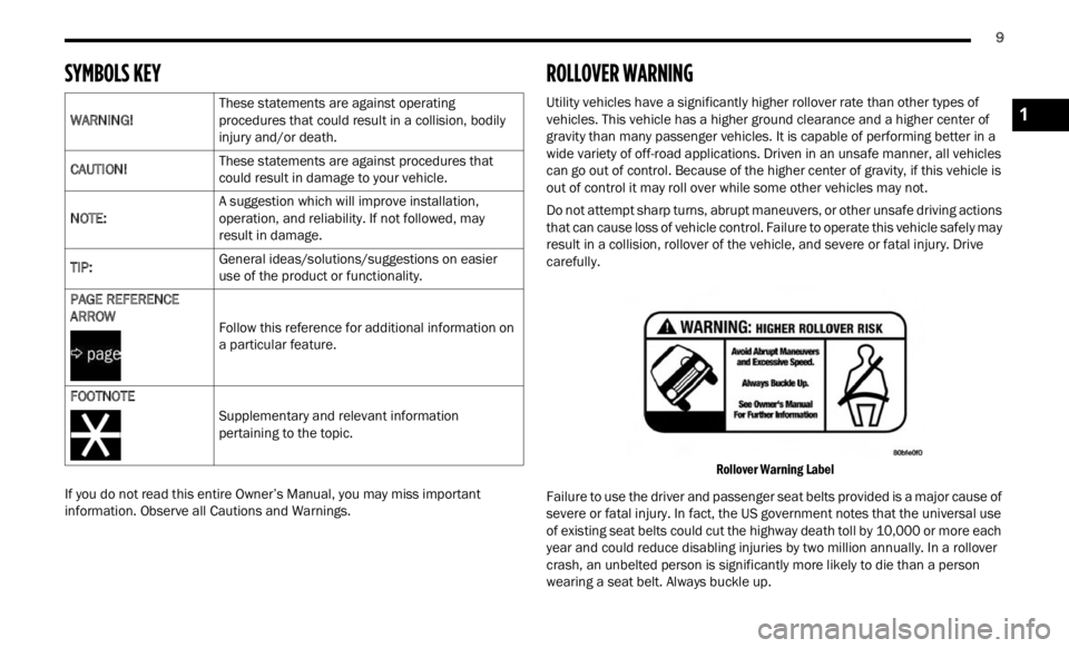
SYMBOLS KEY
If you do not read this entire Owner’s Manual, you may miss important
information. Observe all Cautions and Warnings.
ROLLOVER WARNING
Utility vehicles have a significantly higher rollover rate than other types of
vehicles. This vehicle has a higher ground clearance and a higher center of
gravity than many passenger vehicles. It is capable of performing better in a
wide variety of off-road applications. Driven in an unsafe manner, all vehicles
can go out of control. Because of the higher center of gravity, if this vehicle is
out of control it may roll over while some other vehicles may not.
Do not attempt sharp turns, abrupt maneuvers, or other unsafe driving actions
that c
an cause loss of vehicle control. Failure to operate this vehicle safely may
result in a collision, rollover of the vehicle, and severe or fatal injury. Drive
carefully.
Rollover Warning Label
Failure to use the driver and passenger seat belts provided is a major cause of
sever e
or fatal injury. In fact, the US government notes that the universal use
of existing seat belts could cut the highway death toll by 10,000 or more each
year and could reduce disabling injuries by two million annually. In a rollover
crash, an unbelted person is significantly more likely to die than a person
wearing a seat belt. Always buckle up.
WARNING!
These statements are against operating
proced
u
res that could result in a collision, bodily
injury and/or death.
CAUTION! These statements are against procedures that
could r
esult in damage to your vehicle.
NOTE: A suggestion which will improve installation,
op
erat
i
on, and reliability. If not followed, may
result in damage.
TIP: General ideas/solutions/suggestions on easier
use of
the product or functionality.
PAGE REFERENCE
ARROW Fol
low this reference for additional information on
a par t
icular feature.
FOOTNOTE Supplementary and relevant information
pertai
ning to the topic.
1
Page 77 of 364
GETTING TO KNOW YOUR INSTRUMENT PANEL 75
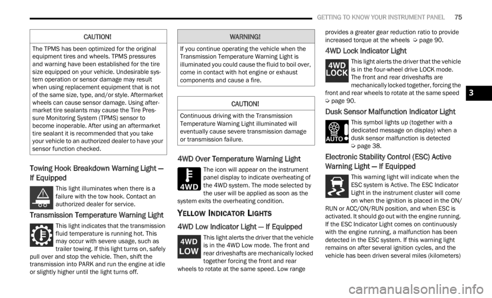
Towing Hook Breakdown Warning Light —
If Equipped
This light illuminates when there is a
failure with the tow hook. Contact an
a ut
h or
i
zed dealer for service.
Transmission Temperature Warning Light
This light indicates that the transmission
fluid temperature is running hot. This
may occ
ur with severe usage, such as
trailer towing. If this light turns on, safely
pull over and stop the vehicle. Then, shift the
transmission into PARK and run the engine at idle
or slightly higher until the light turns off.
4WD Over Temperature Warning Light
The icon will appear on the instrument
panel display to indicate overheating of
t h e
4
W
D system. The mode selected by
the user will be applied as soon as the
system exits the overheating condition.
YELLOW INDICATOR LIGHTS
4WD Low Indicator Light — If Equipped
This light alerts the driver that the vehicle
is in the 4WD Low mode. The front and
rear d
riveshafts are mechanically locked
together forcing the front and rear
wheels to rotate at the same speed. Low range provides a greater gear reduction ratio to provide
increased torque at the wheels
Ú page 90.
4WD Lock Indicator Light
This light alerts the driver that the vehicle
is in the four-wheel drive LOCK mode.
The f r
ont and rear driveshafts are
mechanically locked together, forcing the
front and rear wheels to rotate at the same speed
Ú page 90.
Dusk Sensor Malfunction Indicator Light
This symbol lights up (together with a
dedicated message on display) when a
dusk s
ensor malfunction is detected
Ú page 38.
Electronic Stability Control (ESC) Active
Warning Light — If Equipped
This warning light will indicate when the
ESC system is Active. The ESC Indicator
Light
in the instrument cluster will come
on when the ignition is placed in the ON/
RUN or ACC/ON/RUN position, and when ESC is
activated. It should go out with the engine running.
If the ESC Indicator Light comes on continuously
with the engine running, a malfunction has been
detected in the ESC system. If this warning light
remains on after several ignition cycles, and the
vehicle has been driven several miles (kilometers)
CAUTION!
The TPMS has been optimized for the original
equipment tires and wheels. TPMS pressures
and warning have been established for the tire
size equipped on your vehicle. Undesirable sys -
tem operation or sensor damage may result
w hen u
sing replacement equipment that is not
of the same size, type, and/or style. Aftermarket
wheels can cause sensor damage. Using after -
market tire sealants may cause the Tire Pres -
sure Monitoring System (TPMS) sensor to
b ecome
inoperable. After using an aftermarket
tire sealant it is recommended that you take
your vehicle to an authorized dealer to have your
sensor function checked.
WARNING!
If you continue operating the vehicle when the
Transmission Temperature Warning Light is
illuminated you could cause the fluid to boil over,
come in contact with hot engine or exhaust
components and cause a fire.
CAUTION!
Continuous driving with the Transmission
Temperature Warning Light illuminated will
eventually cause severe transmission damage
or transmission failure.
3
Page 92 of 364

90 STARTING AND OPERATING
TRANSMISSION LIMP HOME MODE
Transmission function is electronically monitored
for abnormal conditions. If a condition is detected
that could result in transmission damage,
Transmission Limp Home Mode is activated. In this
mode, the transmission may operate only in a fixed
gear, or may remain in neutral. The Malfunction
Indicator Light (MIL) may be illuminated. Limp
Home Mode may allow the vehicle to be driven to
an authorized dealer for service without damaging
the transmission.
In the event of a momentary problem, the
trans m
ission can be reset to regain all forward
gears by performing the following steps:
1. Stop the vehicle.
2. S hif
t the transmission into PARK, if possible. If
n ot
,
s
hift the transmission to NEUTRAL.
3. Push and hold the ignition switch until the engin
e turns off.
4. Wait approximately 30 seconds.
5. Res
tart the engine.
6. S hif
t into the desired gear range. If the
p r
ob l
e
m is no longer detected, the
transmission will return to normal operation.
NOTE:
Even if the transmission can be reset, we
recomm e
nd that you visit an authorized dealer at your earliest possible convenience. An authorized
dealer has diagnostic equipment to determine if
the problem could recur. If the transmission
cannot be reset, authorized dealer service is
required.
IGNITION PARK INTERLOCK
(K
EYLESS VEHICLE)
This vehicle is equipped with an Ignition Park
Interlock, which requires the transmission to be in
PARK before the ignition can be turned to the OFF
position. Also, the transmission is locked in PARK
whenever the ignition is in the OFF position.
BRAKE TRANSMISSION SHIFT
I
NTERLOCK (BTSI) SYSTEM
This vehicle is equipped with a BTSI that holds the
transmission gear selector in PARK unless the
brakes are applied. To shift the transmission out of
PARK, the ignition must be in the RUN position
(engine running or not) and the brake pedal must
be pressed.
The brake pedal must also be pressed before
pushi n
g the button on the gear selector to shift
from NEUTRAL into DRIVE or REVERSE when the
vehicle is stopped or moving at low speeds.
FOUR-WHEEL DRIVE
Active Drive (4WD) And Active Drive Low (4WD
LOW)
Your vehicle may be equipped with a Power
Transf
er Unit (PTU). This system is automatic with
no driver inputs or additional driving skills
required. Under normal driving conditions, the
front wheels provide most of the traction. If the
front wheels begin to lose traction, power is shifted
automatically to the rear wheels. The greater the
front wheel traction loss, the greater the power
transfer to the rear wheels.
Additionally, on dry pavement under heavy throttle
input
(where one may have no wheel spin), torque
will be sent to the rear in a preemptive effort to
improve vehicle launch and performance
characteristics.
CAUTION!
All wheels must have the same size and type
tires. Unequal tire sizes must not be used.
Unequal tire size may cause failure of the power
transfer unit.
Page 126 of 364

124 STARTING AND OPERATING
Improper weight distributions can have an adverse
effect on the way your vehicle steers and handles
and the way the brakes operate.
TRAILER TOWING
In this section you will find safety tips and
information on limits to the type of towing you can
reasonably do with your vehicle. Before towing a
trailer, carefully review this information to tow your
load as efficiently and safely as possible.
To maintain the New Vehicle Limited Warranty
covera g
e, follow the requirements and
recommendations in this manual concerning
vehicles used for trailer towing.
COMMON TOWING DEFINITIONS
The following trailer towing related definitions will
assist you in understanding the following
information:
Gross Vehicle Weight Rating (GVWR)
The GVWR is the total allowable weight of your
vehicle. This includes driver, passengers, cargo
and tongue weight. The total load must be limited
so that you do not exceed the GVWR Ú page 123.
Gross Trailer Weight (GTW)
The GTW is the weight of the trailer plus the weight
of all cargo, consumables and equipment
(permanent or temporary) loaded in or on the
trailer in its "loaded and ready for operation"
condition.
The recommended way to measure GTW is to put
your f u
lly loaded trailer on a vehicle scale. The
entire weight of the trailer must be supported by
the scale.
Gross Combination Weight Rating (GCWR)
The GCWR is the total allowable weight of your
vehicle and trailer when weighed in combination.
Gross Axle Weight Rating (GAWR)
The GAWR is the maximum capacity of the front
and rear axles. Distribute the load over the front
and rear axles evenly. Make sure that you do not
exceed either front or rear GAWR Ú page 123.
Tongue Weight (TW)
The TW is the downward force exerted on the hitch
ball by the trailer. You must consider this as part of
the load on your vehicle.
Frontal Area
The frontal area is the maximum height multiplied
by the maximum width of the front of a trailer.
Trailer Sway Control (TSC)
The TSC is a telescoping link that can be installed
between the hitch receiver and the trailer tongue
that typically provides adjustable friction
associated with the telescoping motion to dampen
any unwanted trailer swaying motions while
traveling.
CAUTION!
Do not load your vehicle any heavier than the
GVWR or the maximum front and rear GAWR. If
you do, parts on your vehicle can break, or it can
change the way your vehicle handles. This could
cause you to lose control. Also overloading can
shorten the life of your vehicle.WARNING!
It is important that you do not exceed the
maximum front or rear GAWR. A dangerous
driving condition can result if either rating is
exceeded.
Page 128 of 364
126 STARTING AND OPERATING
(Continued)
TRAILER TOWING WEIGHTS (MAXIMUM TRAILER WEIGHT RATINGS)
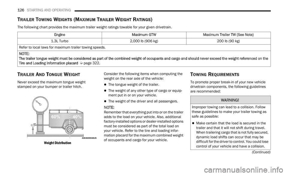
The following chart provides the maximum trailer weight ratings towable for your given drivetrain.
TRAILER AND TONGUE WEIGHT
Never exceed the maximum tongue weight
stamped on your bumper or trailer hitch.
Weight Distribution
Consider the following items when computing the
weight
on the rear axle of the vehicle:
The tongue weight of the trailer.
The weight of any other type of cargo or equip -
ment put in or on your vehicle.
The weight of the driver and all passengers.
NOTE:
Remember that everything put into or on the trailer
adds t
o the load on your vehicle. Also, additional
factory-installed options or dealer-installed options
must be considered as part of the total load on
your vehicle. Refer to the tire and loading infor -
mation placard for the maximum combined weight
of occu p
ants and cargo for your vehicle.
TOWING REQUIREMENTS
To promote proper break-in of your new vehicle
drivetrain components, the following guidelines
are recommended:
Engine
Maximum GTWMaximum Trailer TW (See Note)
1.3L Turbo 2,000 lb (906 kg) 200 lb (90 kg)
Refer to local laws for maximum trailer towing speeds.
NOTE:
The trailer tongue weight must be considered as part of the combined weight of occupants and cargo and should never exceed the weight referenced on the
Tire a
nd Loading Information placard Ú page 322.
WARNING!
Improper towing can lead to a collision. Follow
these guidelines to make your trailer towing as
safe as possible:
Make certain that the load is secured in the
trailer and that it will not shift during travel.
When trailering cargo that is not fully secured,
dynamic load shifts can occur that may be
difficult for the driver to control. You could lose
control of your vehicle and have a collision.
Page 217 of 364

MULTIMEDIA 215
Speed Alert
Receive a notification whenever your car
exceed
s a speed limit you set.
Valet Alert
Receive a notification if and when your vehicle is
driven
outside a quarter-mile radius of a valet
drop-off zone.
SmartWatch Integration — If Equipped
Description
SmartWatch Integration puts the Mobile App right
on your
Apple® Watch or Android™ Wear. To get
started, follow these steps:
1. Download the Mobile App from the App Store ®
or Google Play.
2. Log onto the app from your smartphone using the u
sername and password you created when
you first set up your account.
3. Make sure your watch and smartphone are conne c
ted through Bluetooth®.
4. The Mobile App should appear on your Smart
Watch.
Once the app is downloaded on your SmartWatch,
you can
enjoy these features:
Lock or unlock your vehicle by tapping the
remote lock button in the app and entering your
security PIN.
Remote start or stop your vehicle.
View important vehicle stats, such as fuel level,
vehicle location, tire pressure warning, and
more.
For help, refer to the Uconnect YouTube channel
for Sm a
rtWatch Integration.
MANAGE MY SIRIUSXM GUARDIAN™
A
CCOUNT
To manage your SiriusXM Guardian™ account,
press the ASSIST button in your vehicle, or call
SiriusXM Guardian™ Customer Care.
NOTE:
It is recommended, when selling your vehicle, or
turni n
g in your lease, to call SiriusXM Guardian™
Care to remove your personal data.
CONNECTED SERVICES FAQS
For additional information about SiriusXM
Guardian™, active subscribers can push the
ASSIST button (if equipped) and then select
SiriusXM Guardian™ Call on your in-vehicle
touchscreen to contact SiriusXM Guardian™. Your
call will be directed to a SiriusXM Guardian™ agent
or held in a queue until an agent is available. If you
do not have an active subscription, push the
ASSIST button and press the Activate button on the
touchscreen to activate services.
CONNECTED SERVICES SOS FAQS —
I
F EQUIPPED
1.
What happens if I accidentally push the SOS
Call button on the mirror or overhead console?
You have 10 seconds after pushing the SOS
Call button to cancel the call. To cancel the
call, either push the SOS Call button again, or
press the Cancel button on the in-vehicle
touchscreen.
2. What type of information is sent when I use the
SOS C
all button from my vehicle? Certain
vehicle information, such as make and model,
is transmitted along with the last known GPS
location.
3. When could I use the SOS Call button? You c
an
use the SOS Call button to make a call if you or
someone else needs emergency assistance.
CONNECTED SERVICES REMOTE DOOR
L
OCK/UNLOCK FAQS
1.
How long does it take to unlock or lock the
door?
Depending on various conditions, it can
take up to three minutes or more for the
request to get to your vehicle.
2. Which is faster, my key fob or the Mobile App?
Your k
ey fob will lock/unlock the door more
quickly, however its range is limited and your
Mobile App comes in handy for these and
other situations.
5
Page 225 of 364
SAFETY 223
Electronic Stability Control (ESC)
ESC enhances directional control and stability of
the vehicle under various driving conditions. ESC
corrects for oversteering or understeering of the
vehicle by applying the brake of the appropriate
wheel(s) to counteract the above conditions.
Engine power may also be reduced to help the
vehicle maintain the desired path.
Oversteer — when the vehicle is turning more
than appropriate for the steering wheel position.
Understeer — when the vehicle is turning less
than appropriate for the steering wheel position.
ESC uses sensors in the vehicle to determine the
vehicl
e path intended by the driver and compares
it to the actual path of the vehicle. When the actual
path does not match the intended path, ESC
applies the brake of the appropriate wheel to
assist in counteracting the oversteer or understeer
condition.
The ESC Activation/Malfunction Indicator Light
locate d
in the instrument cluster will start to flash
as soon as the ESC system becomes active. The
ESC Activation/Malfunction Indicator Light also
flashes when the TCS is active. If the ESC
Activation/Malfunction Indicator Light begins to
flash during acceleration, ease up on the
accelerator and apply as little throttle as possible.
Be sure to adapt your speed and driving to the
prevailing road conditions.
WARNING!
Many factors, such as vehicle loading, road
conditions, and driving conditions, influence the
chance that wheel lift or rollover may occur.
Electronic Roll Mitigation (ERM) cannot prevent
all wheel lift or rollovers, especially those that
involve leaving the roadway or striking objects or
other vehicles. The capabilities of an
ERM-equipped vehicle must never be exploited
in a reckless or dangerous manner, which could
jeopardize the user's safety or the safety of
others.
WARNING!
Electronic Stability Control (ESC) cannot
prevent the natural laws of physics from acting
on the vehicle, nor can it increase the traction
afforded by prevailing road conditions. ESC
cannot prevent accidents, including those
resulting from excessive speed in turns, driving
on very slippery surfaces, or hydroplaning. ESC
also cannot prevent accidents resulting from
loss of vehicle control due to inappropriate
driver input for the conditions. Only a safe,
attentive, and skillful driver can prevent acci -
dents. The capabilities of an ESC equipped
vehic l
e must never be exploited in a reckless or
dangerous manner which could jeopardize the
user’s safety or the safety of others.
Vehicle modifications, or failure to properly
maintain your vehicle, may change the handling
characteristics of your vehicle, and may nega -
tively affect the performance of the ESC system.
Chang e
s to the steering system, suspension,
braking system, tire type and size or wheel size
may adversely affect ESC performance. Improp -
erly inflated and unevenly worn tires may also
d egrad
e ESC performance. Any vehicle modifi-
cation or poor vehicle maintenance that
r educe
s the effectiveness of the ESC system
can increase the risk of loss of vehicle control,
vehicle rollover, personal injury and death.
6
Page 238 of 364

236 SAFETY
The TPMS will continue to warn the driver of low
tire pressure as long as the condition exists, and
will not turn off until the tire pressure is at or above
the recommended cold placard pressure. Once the
low tire pressure warning (Tire Pressure Monitoring
System Light) illuminates, you must increase the
tire pressure to the recommended cold placard
pressure in order for the TPMS Warning Light to
turn off.
The system will automatically update and the Tire
Press u
re Monitoring System Light will turn off once
the system receives the updated tire pressures.
The vehicle may need to be driven for up to
20 minutes above 15 mph (24 km/h) in order for
the TP
MS to receive this information.
For example, your vehicle may have a recommended
cold (
parked for more than three hours) placard
pressure of 33 psi (227 kPa). If the ambient
temperature is 68°F (20°C) and the measured tire
pressure is 28 psi (193 kPa), a temperature drop to
20°F (-7°C) will decrease the tire pressure to
approximately 24 psi (165 kPa). This tire pressure is
low enough to turn on the Tire Pressure Monitoring
System Light. Driving the vehicle may cause the tire
pressure to rise to approximately 28 psi (193 kPa),
but the Tire Pressure Monitoring System Light will
still be on. In this situation, the Tire Pressure
Monitoring System Light will turn off only after the
tires are inflated to the vehicle’s recommended cold
placard pressure value.
NOTE:
When filling warm tires, the tire pressure may need
to be i
ncreased up to an additional 4 psi (28 kPa)
above the recommended cold placard pressure in
order to turn the Tire Pressure Monitoring System
Light off.NOTE:
The TPMS is not intended to replace normal tire
care and maintenance, or to provide warning of
a tire failure or condition.
The TPMS should not be used as a tire pressure
gauge while adjusting your tire pressure, unless
your vehicle is equipped with a Tire Fill Alert
(TFA) system.
Driving on a significantly underinflated tire
causes the tire to overheat and can lead to tire
failure. Underinflation also reduces fuel effi -
ciency and tire tread life, and may affect the
vehic l
e’s handling and stopping ability.
The TPMS is not a substitute for proper tire
maintenance, and it is the driver’s responsibility
to maintain correct tire pressure using an accu -
rate tire pressure gauge, even if underinflation
has n ot
reached the level to trigger illumination
of the Tire Pressure Monitoring System Light.
Seasonal temperature changes will affect TPMS
information on your instrument cluster
Ú page 349.
Base System
The Tire Pressure Monitoring System (TPMS) uses
wireless technology with wheel rim mounted
electronic sensors to monitor tire pressure levels.
Sensors, mounted to each wheel as part of the
valve stem, transmit tire pressure readings to the
receiver module.
CAUTION!
The TPMS has been optimized for the original
equipment tires and wheels. TPMS pressures
and warning have been established for the tire
size equipped on your vehicle. Undesirable
system operation or sensor damage may result
when using replacement equipment that is not
of the same size, type, and/or style. The TPMS
sensor is not designed for use on aftermarket
wheels, and may contribute to a poor overall
system performance. Customers are encour
-
aged to use OEM wheels to ensure TPMS feature
o pera t
ion.
Using aftermarket tire sealants may cause the
Tire Pressure Monitoring System (TPMS) sensor
to become inoperable. After using an after -
market tire sealant it is recommended that you
take y
our vehicle to an authorized dealer to have
your sensor function checked.
After inspecting or adjusting the tire pressure
always reinstall the valve stem cap. This will
prevent moisture and dirt from entering the valve
stem, which could damage the TPMS sensor.
Page 331 of 364
SERVICING AND MAINTENANCE 329
(Continued)
TIRES — GENERAL INFORMATION
Tire Pressure
Proper tire inflation pressure is essential to the
safe and satisfactory operation of your vehicle.
Four primary areas are affected by improper tire
pressure:
Safety
Fuel Economy
Tread Wear
Ride Comfort And Vehicle Stability
Safety Both underinflation and overinflation affect the
stabil
ity of the vehicle and can produce a feeling of
sluggish response or over responsiveness in the
steering.
NOTE:
Unequal tire pressures from side to side may
cause erratic and unpredictable steering
response.
Unequal tire pressure from side to side may
cause the vehicle to drift left or right.
Fuel Economy
Underinflated tires will increase tire rolling
resis t
ance resulting in higher fuel consumption. Tread Wear
Improper cold tire inflation pressures can cause
a
bnorm a
l wear patterns and reduced tread life,
resulting in the need for earlier tire replacement.
Ride Comfort And Vehicle Stability
Proper tire inflation contributes to a comfortable
ride.
Overinflation produces a jarring and
uncomfortable ride.
Tire Inflation Pressures
The proper cold tire inflation pressure is listed on
the driver's side B-pillar or rear edge of the driver's
side door.
At least once a month:
Check and adjust tire pressure with a good
quality pocket-type pressure gauge. Do not
make a visual judgment when determining
proper inflation. Tires may look properly inflated
even when they are under-inflated.
Inspect tires for signs of tire wear or visible
damage.
WARNING!
Improperly inflated tires are dangerous and
can cause collisions.
Underinflation increases tire flexing and can
result in overheating and tire failure.
Overinflation reduces a tire's ability to cushion
shock. Objects on the road and chuckholes
can cause damage that result in tire failure.
Overinflated or underinflated tires can affect
vehicle handling and can fail suddenly,
resulting in loss of vehicle control.
Unequal tire pressures can cause steering
problems. You could lose control of your
vehicle.
Unequal tire pressures from one side of the
vehicle to the other can cause the vehicle to
drift to the right or left.
Always drive with each tire inflated to the
recommended cold tire inflation pressure.
WARNING!
CAUTION!
After inspecting or adjusting the tire pressure,
always reinstall the valve stem cap. This will
prevent moisture and dirt from entering the
valve stem, which could damage the valve stem.
8