tow bar JEEP RENEGADE 2023 Owners Manual
[x] Cancel search | Manufacturer: JEEP, Model Year: 2023, Model line: RENEGADE, Model: JEEP RENEGADE 2023Pages: 364, PDF Size: 18.65 MB
Page 6 of 364

4
FOUR-WHEEL DRIVE .............................................. 90
Four-Wheel Drive (4WD) ...... ............................91
SELEC-TERRAIN ..... . ............................................... 92
Mode Selection Guide...... ................................92
ACTIVE GRILLE SHUTTERS — IF EQUIPPED ..... . .. 93
POWER STEERING ...... ........................................... 93
STOP/START SYSTEM ...... ..................................... 93
Autostop Mode ......
...........................................93
Possible Reasons The Engine Does Not
Autostop . ...........................................................94
To Sta
rt The Engine While In Autostop
Mode . ................................................................94
To Man
ually Turn Off The Stop/Start
System . .............................................................95
To Man
ually Turn On The Stop/Start
System . .............................................................95
Syste
m Malfunction ..... . ...................................95
CRUISE CONTROL SYSTEMS — IF EQUIPPED. ..
. .
9 5
Cruise Control ...... ............................................95
Adaptive Cruise Control (ACC) . ..
. .
. ...................97
PARKSENSE FRONT/REAR PARK ASSIST
SYSTEM — IF EQUIPPED ..... .
.............................. 105
ParkSense Sensors ...... ................................. 105
ParkSense Warning Display..... . .................... 105
ParkSense Display . ..
..
. .................................. 105
Enabling And Disabling ParkSense ..... . ........ 108
Service The ParkSense Park Assist System .. 108
C l
eaning The ParkSense System . ..
..
. ........... 108
ParkSense System Usage Precautions ..... . .. 108
Side Distance Warning (SDW) System . ..
. .
. ... 109PARKSENSE ACTIVE PARK ASSIST SYSTEM —
IF EQUIPPED ..... .
.................................................. 111
Enabling And Disabling The ParkSense
Active Park Assist System..... .
....................... 112
Parallel/Perpendicular Parking Space
Assistance Operation . .....
.............................. 113
Exiting The Parking Space ..... . ...................... 115
LANESENSE — IF EQUIPPED . ..
. .
. ....................... 117
LaneSense Operation ...... ............................. 117
Turning LaneSense On Or Off ..... . ................. 117
LaneSense Warning Message . ..
..
. ................ 117
Changing LaneSense Status ..... . .................. 121
REAR BACK UP CAMERA . ..
..
. ............................. 121
REFUELING THE VEHICLE ...... ............................ 122
VEHICLE LOADING ...... ....................................... 123
Certification Label ...... ................................... 123
TRAILER TOWING ..... . .......................................... 124
Common Towing Definitions...... ................... 124
Trailer Hitch Classification ..... . ...................... 125
Trailer Towing Weights (Maximum Trailer
Weight Ratings) . .....
....................................... 126
Trailer And Tongue Weight..... . ...................... 126
Towing Requirements . ..
..
. ............................ 126
Towing Tips ..... . .............................................. 128
RECREATIONAL TOWING . ..
..
. ............................. 129
Towing This Vehicle Behind Another
Vehicle ........................................................... 129
Recr e
ational Towing. ..
..
. ................................ 129 DRIVING TIPS .....
.
................................................. 130
On-Road Driving Tips...... ............................... 130
Off-Road Driving Tips ..... . .............................. 130
MULTIMEDIA
UCONNECT SYSTEMS ......................................... 133
CYBERSECURITY ................................................. 133
UCONNECT SETTINGS ...... ................................... 133
Customer Programmable Features ...... ...... 134
UCONNECT INTRODUCTION..... . .......................... 147
System Overview ...... .................................... 147
Drag & Drop Menu Bar . ..
..
. ........................... 149
Safety And General Information..... . ............. 149
UCONNECT MODES ..... . ....................................... 150
Steering Wheel Audio Controls .................... 150
Radi o Mode ..... . ............................................ 151
Media Mode . ..
. .
. ........................................... 162
Phone Mode ..... . ........................................... 164
ANDROID AUTO™ & APPLE CARPLAY® —
IF EQUIPPED ..... .
................................................... 174
Android Auto™ ...... ........................................ 174
Apple CarPlay® . ..
..
. ....................................... 176
Android Auto™ And Apple CarPlay® Tips
And Tricks . ..................................................... 178
Page 47 of 364
GETTING TO KNOW YOUR VEHICLE 45
(button on the touchscreen grayed out) if
conditions exist that could create fogging on the
inside of the windshield. The A/C can be
deselected manually without disturbing the mode
control selection. Continuous use of the
Recirculation mode may make the inside air stuffy
and window fogging may occur. Extended use of
this mode is not recommended. Recirculation
mode may automatically adjust to optimize
customer experience for warming, cooling,
dehumidification, etc.
In cold weather, use of Recirculation mode may
lead t
o excessive window fogging. The
Recirculation feature may be unavailable if
conditions exist that could create fogging on the
inside of the windshield.
AUTO Button
Press and release this button on the
touchscreen, or push the button on the
facep l
ate, to change the current setting.
The AUTO indicator illuminates when
AUTO is on. This feature automatically controls the
interior cabin temperature by adjusting distribution
and amount of airflow. Air Conditioning (A/C) may
be active during AUTO operation to improve
performance. Toggling this function will cause the
system to switch between manual override mode
and automatic modes Ú page 47.
Front Defrost Button
Press and release the touchscreen
button, or push and release the button
on the
faceplate, to change the current
airflow setting to Defrost mode. The Front
Defrost indicator illuminates when Front Defrost is
on. Air comes from the windshield and side window
demist outlets. When the defrost button is
selected, the blower level may increase. Use
Defrost mode with maximum temperature settings
for best windshield and side window defrosting
and defogging. When toggling the front defrost
mode button, the Climate Control system will
return to the previous setting.
Rear Defrost Button
Press and release the button on the
touchscreen, or push and release the
button
on the faceplate, to turn on the
rear window defroster and the heated
outside mirrors (if equipped). The Rear Defrost
indicator illuminates when the rear window
defroster is on. The rear window defroster
automatically turns off after 20 minutes.Driver And Passenger Up And Down
Buttons
These buttons provide the driver and passenger
with independent temperature control.
Push the red button on the faceplate or
touchscreen or press and slide the
temper
ature bar towards the red arrow
button on the touchscreen for warmer
temperature settings.
CAUTION!
Failure to follow these cautions can cause
damage to the heating elements:
Use care when washing the inside of the rear
window. Do not use abrasive window cleaners
on the interior surface of the window. Use a
soft cloth and a mild washing solution, wiping
parallel to the heating elements. Labels can
be peeled off after soaking with warm water.
Do not use scrapers, sharp instruments, or
abrasive window cleaners on the interior
surface of the window.
Keep all objects a safe distance from the
window.
2
Page 48 of 364
46 GETTING TO KNOW YOUR VEHICLE
Push the blue button on the faceplate or
touchscreen or press and slide the
tempe r
ature bar towards the blue arrow
button on the touchscreen for cooler
temperature settings.
SYNC Button
Press the SYNC button on the
touchscreen to toggle the Sync feature
on/off.
The SYNC indicator is illuminated
when SYNC is on. SYNC is used to
synchronize the passenger temperature setting
with the driver temperature setting. Changing the
passenger temperature setting while in SYNC will
automatically exit this feature.
NOTE:
The SYNC button is only available on the touch-
screen.
Blower Control
Blower Control is used to regulate the
amount of air forced through the Climate
Control
system. There are seven blower
speeds available. Adjusting the blower
will cause automatic mode to switch to manual
operation. The speeds can be selected using either
the blower control knob on the faceplate or the
buttons on the touchscreen. Faceplate
The blower speed increases as you turn the blower
c
ontrol
knob clockwise from the lowest blower
setting. The blower speed decreases as you turn
the blower control knob counterclockwise.
Touchscreen
Use the small blower icon to reduce the blower
setti n
g and the large blower icon to increase the
blower setting. Blower can also be selected by
pressing the blower bar area between the icons.
Mode Control
Select Mode by pressing one of the Mode
buttons on the touchscreen to change
the a i
rflow distribution mode. The airflow
distribution outlets are: instrument panel
outlets, floor outlets, defrost outlets, and demist
outlets.
Panel Mode
Air comes from the outlets in the
instrument panel. Each of these outlets
can b e
individually adjusted to direct the
flow of air. The air vanes of the center
outlets and outboard outlets can be moved up and
down or side to side to regulate airflow direction.
There is a shut-off wheel located below the air
vanes to shut off or adjust the amount of airflow
from these outlets.
Bi-Level Mode
Air comes from the instrument panel
outlets and floor outlets. A slight amount
of ai r
is directed through the defrost and
side window demister outlets.
NOTE:
Bi-Level mode is designed under comfort condi -
tions to provide cooler air out of the panel outlets
a nd w a
rmer air from the floor outlets.
Floor Mode
Air comes from the floor outlets. A slight
amount of air is directed through the
defrost
, side window demister outlets,
and panel outboard outlets.
Mix Mode
Air is directed through the floor, defrost,
and side window demister outlets. This
setti n
g works best in cold or snowy
conditions that require extra heat to the
windshield. This setting is good for maintaining
comfort while reducing moisture on the
windshield. A slight amount of air is also directed
through the panel outboard outlets.
Climate Control OFF Button
Press and release this button to turn the
Climate Control ON/OFF.
Page 125 of 364

STARTING AND OPERATING 123
VEHICLE LOADING
CERTIFICATION LABEL
As required by National Highway Traffic Safety
Administration regulations, your vehicle has a
certification label affixed to the driver's side door or
pillar
Ú page 322.
This label contains the month and year of
m anufa
cture, Gross Vehicle Weight Rating
(GVWR), Gross Axle Weight Rating (GAWR) front
and rear, and Vehicle Identification Number (VIN).
A Month-Day-Hour (MDH) number is included on
this label and indicates the Month, Day and Hour of
manufacture. The bar code that appears on the
bottom of the label is your VIN.
Gross Vehicle Weight Rating (GVWR)
The GVWR is the total permissible weight of your
vehicle including driver, passengers, vehicle,
options and cargo. The label also specifies
maximum capacities of front and rear axle systems
(GAWR). Total load must be limited so GVWR and
front and rear GAWR are not exceeded.
Payload
The payload of a vehicle is defined as the allowable
load weight a truck can carry, including the weight
of the driver, all passengers, options and cargo.
Gross Axle Weight Rating (GAWR)
The GAWR is the maximum permissible load on the
front and rear axles. The load must be distributed
in the cargo area so that the GAWR of each axle is
not exceeded.
Each axle GAWR is determined by the components
in the
system with the lowest load carrying capacity
(axle, springs, tires or wheels). Heavier axles or
suspension components sometimes specified by
purchasers for increased durability does not
necessarily increase the vehicle's GVWR.
Tire Size
The tire size on the Vehicle Certification Label
represents the actual tire size on your vehicle.
Replacement tires must be equal to the load
capacity of this tire size.
Rim Size
This is the rim size that is appropriate for the tire
size listed.
Inflation Pressure
This is the cold tire inflation pressure for your
vehicle for all loading conditions up to full GAWR.
Curb Weight
The curb weight of a vehicle is defined as the total
weight of the vehicle with all fluids, including
vehicle fuel, at full capacity conditions, and with no
occupants or cargo loaded into the vehicle. The
front and rear curb weight values are determined
by weighing your vehicle on a commercial scale
before any occupants or cargo are added.
Loading
The actual total weight and the weight of the front
and rear of your vehicle at the ground can best be
determined by weighing it when it is loaded and
ready for operation.
The entire vehicle should first be weighed on a
commerc
ial scale to ensure that the GVWR has not
been exceeded. The weight on the front and rear of
the vehicle should then be determined separately
to be sure that the load is properly distributed over
the front and rear axle. Weighing the vehicle may
show that the GAWR of either the front or rear axles
has been exceeded but the total load is within the
specified GVWR. If so, weight must be shifted from
front to rear or rear to front as appropriate until the
specified weight limitations are met. Store the
heavier items down low and be sure that the
weight is distributed equally. Stow all loose items
securely before driving.
4
Page 127 of 364

STARTING AND OPERATING 125
Weight-Carrying Hitch
A weight-carrying hitch supports the trailer tongue
weight, just as if it were luggage located at a hitch
ball or some other connecting point of the vehicle.
These kinds of hitches are commonly used to tow
small and medium sized trailers.
Weight-Distributing Hitch
A weight-distributing system works by applying
leverage through spring (load) bars. They are
typically used for heavier loads to distribute trailer
tongue weight to the tow vehicle's front axle and the trailer axle(s). When used in accordance with
vehicle manufacturer’s directions, it provides for a
more level ride, offering more consistent steering
and brake control thereby enhancing towing
safety. The addition of a friction/hydraulic sway
control also dampens sway caused by traffic and
crosswinds and contributes positively to tow
vehicle and trailer stability. Trailer sway control and
a weight-distributing (load equalizing) hitch are
recommended for heavier Tongue Weights (TW)
and may be required depending on vehicle and
trailer configuration/loading to comply with Gross
Axle Weight Rating (GAWR) requirements.
TRAILER HITCH CLASSIFICATION
The following chart provides the industry standard for the maximum trailer weight a given trailer hitch class can tow and should be used to assist you in selecting
the correct trailer hitch for your intended towing condition.
WARNING!
An improperly adjusted weight-distributing
hitch system may reduce handling, stability,
braking performance, and could result in a
collision.
Weight-distributing systems may not be
compatible with surge brake couplers. Consult
with your hitch and trailer manufacturer or a
reputable Recreational Vehicle dealer for
additional information.
Trailer Hitch Classification Definitions
Class
Max. Trailer Hitch Industry Standards
Class I - Light Duty 2,000 lb (907 kg)
Class II - Medium Duty 3,500 lb (1,587 kg)
Class III - Heavy Duty 6,000 lb (2,722 kg)
Class IV - Extra Heavy Duty 10,000 lb (4,535 kg)
Refer to the “Trailer Towing Weights (Maximum Trailer Weight Ratings)” chart for the Maximum Gross Trailer Weight (GTW) towable for your given drivetrain.
All trailer hitches should be professionally installed on your vehicle.
4
Page 263 of 364
SAFETY 261
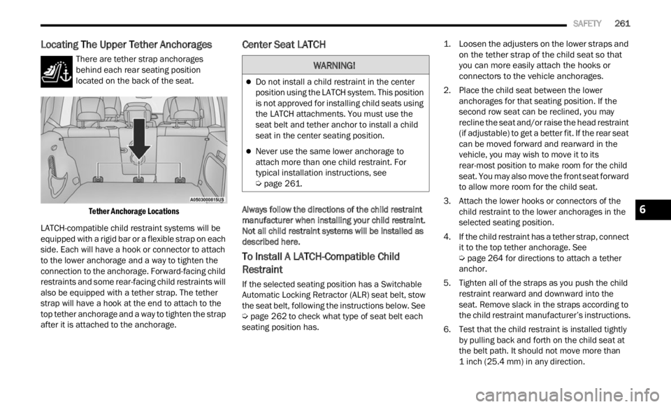
Locating The Upper Tether Anchorages
There are tether strap anchorages
behind each rear seating position
locate d
on the back of the seat.
Tether Anchorage Locations
LATCH-compatible child restraint systems will be
equip p
ed with a rigid bar or a flexible strap on each
side. Each will have a hook or connector to attach
to the lower anchorage and a way to tighten the
connection to the anchorage. Forward-facing child
restraints and some rear-facing child restraints will
also be equipped with a tether strap. The tether
strap will have a hook at the end to attach to the
top tether anchorage and a way to tighten the strap
after it is attached to the anchorage.
Center Seat LATCH
Always follow the directions of the child restraint
manufacturer when installing your child restraint.
Not all child restraint systems will be installed as
described here.
To Install A LATCH-Compatible Child
Restraint
If the selected seating position has a Switchable
Automatic Locking Retractor (ALR) seat belt, stow
the seat belt, following the instructions below. See
Ú page 262 to check what type of seat belt each
seating position has.
1. L
oosen the adjusters on the lower straps and
on t he
tether strap of the child seat so that
you can more easily attach the hooks or
connectors to the vehicle anchorages.
2. Place the child seat between the lower anchor
ages for that seating position. If the
second row seat can be reclined, you may
recline the seat and/or raise the head restraint
(if adjustable) to get a better fit. If the rear seat
can be moved forward and rearward in the
vehicle, you may wish to move it to its
rear-most position to make room for the child
seat. You may also move the front seat forward
to allow more room for the child seat.
3. Attach the lower hooks or connectors of the child
restraint to the lower anchorages in the
selected seating position.
4. If the child restraint has a tether strap, connect it to
the top tether anchorage. See
Ú page 264 for directions to attach a tether
anchor.
5. T ighten all of the straps as you push the child
restr
aint rearward and downward into the
seat. Remove slack in the straps according to
the child restraint manufacturer’s instructions.
6. Test that the child restraint is installed tightly by pu
lling back and forth on the child seat at
the belt path. It should not move more than
1 inch (25.4 mm) in any direction.
WARNING!
Do not install a child restraint in the center
position using the LATCH system. This position
is not approved for installing child seats using
the LATCH attachments. You must use the
seat belt and tether anchor to install a child
seat in the center seating position.
Never use the same lower anchorage to
attach more than one child restraint. For
typical installation instructions, see
Ú page 261.
6
Page 279 of 364
IN CASE OF EMERGENCY 277
(Continued)
If the pressure is at 19 psi (1.3 bar) or above
repeat the inflation process to reach the cor -
rect tire pressure and continue driving.
5. Peel off the warning label from the bottle and plac e
it on the dashboard as a reminder to the
driver that the tire has been treated with Tire
Service Kit.
TIRE SERVICE KIT USAGE PRECAUTIONSWARNING!
Tire Service Kit is not a permanent flat tire
repair. Have the tire inspected and repaired or
replaced after using Tire Service Kit. Do not
exceed 50 mph (80 km/h) until the tire is
repai r
ed or replaced. Failure to follow this
warning can result in injuries that are serious or
fatal to you, your passengers, and others around
you. Have the tire checked as soon as possible
at an authorized dealer.
WARNING!
The metal end fitting from Power Plug may get
hot after use, so it should be handled carefully.
WARNING!
Do not attempt to seal a tire on the side of the
vehicle closest to traffic. Pull far enough off
the road to avoid the danger of being hit when
using the Tire Service Kit.
Do not use Tire Service Kit or drive the vehicle
under the following circumstances:
If the puncture in the tire tread is approxi -
mately 1/4 inch (6 mm) or larger.
If the tire has any sidewall damage.
If the tire has any damage from driving
with extremely low tire pressure.
If the tire has any damage from driving on
a flat tire.
If the wheel has any damage.
If you are unsure of the condition of the
tire or the wheel.
Keep Tire Service Kit away from open flames
or heat source.
A loose Tire Service Kit thrown forward in a
collision or hard stop could endanger the
occupants of the vehicle. Always stow the Tire
Service Kit in the place provided. Failure to
follow these warnings can result in injuries
that are serious or fatal to you, your passen
-
gers, and others around you.
Take care not to allow the contents of Tire
Service Kit to come in contact with hair, eyes,
or clothing. Tire Service Kit sealant is harmful
if inhaled, swallowed, or absorbed through the
skin. It causes skin, eye, and respiratory irrita -
tion. Flush immediately with plenty of water if
there
is any contact with eyes or skin. Change
clothing as soon as possible, if there is any
contact with clothing.
Tire Service Kit Sealant solution contains
latex. In case of an allergic reaction or rash,
consult a physician immediately. Keep Tire
Service Kit out of reach of children. If swal -
lowed, rinse mouth immediately with plenty of
w ater
and drink plenty of water. Do not induce
vomiting! Consult a physician immediately.
WARNING!
7
Page 285 of 364
IN CASE OF EMERGENCY 283
(Continued)
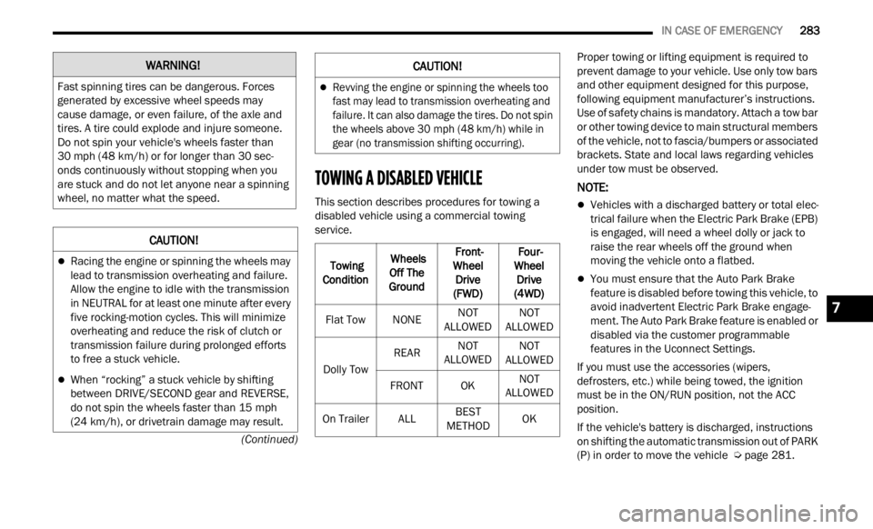
TOWING A DISABLED VEHICLE
This section describes procedures for towing a
disabled vehicle using a commercial towing
service. Proper towing or lifting equipment is required to
preve
n
t damage to your vehicle. Use only tow bars
and other equipment designed for this purpose,
following equipment manufacturer’s instructions.
Use of safety chains is mandatory. Attach a tow bar
or other towing device to main structural members
of the vehicle, not to fascia/bumpers or associated
brackets. State and local laws regarding vehicles
under tow must be observed.
NOTE:
Vehicles with a discharged battery or total elec -
trical failure when the Electric Park Brake (EPB)
is en g
aged, will need a wheel dolly or jack to
raise the rear wheels off the ground when
moving the vehicle onto a flatbed.
You must ensure that the Auto Park Brake
feature is disabled before towing this vehicle, to
avoid inadvertent Electric Park Brake engage -
ment. The Auto Park Brake feature is enabled or
disab l
ed via the customer programmable
features in the Uconnect Settings.
If you must use the accessories (wipers,
defros t
ers, etc.) while being towed, the ignition
must be in the ON/RUN position, not the ACC
position.
If the vehicle's battery is discharged, instructions
on shif
ting the automatic transmission out of PARK
(P) in order to move the vehicle Ú page 281.
WARNING!
Fast spinning tires can be dangerous. Forces
generated by excessive wheel speeds may
cause damage, or even failure, of the axle and
tires. A tire could explode and injure someone.
Do not spin your vehicle's wheels faster than
30
mph (48 km/h) or for longer than 30 sec-
onds c on
tinuously without stopping when you
are stuck and do not let anyone near a spinning
wheel, no matter what the speed.
CAUTION!
Racing the engine or spinning the wheels may
lead to transmission overheating and failure.
Allow the engine to idle with the transmission
in NEUTRAL for at least one minute after every
five rocking-motion cycles. This will minimize
overheating and reduce the risk of clutch or
transmission failure during prolonged efforts
to free a stuck vehicle.
When “rocking” a stuck vehicle by shifting
between DRIVE/SECOND gear and REVERSE,
do not spin the wheels faster than 15 mph
(24 km/
h), or drivetrain damage may result.
Revving the engine or spinning the wheels too
fast may lead to transmission overheating and
failure. It can also damage the tires. Do not spin
the wheels above 30 mph (48 km/h) while in
gear (
no transmission shifting occurring).
Towing
Condit i
on Wheels
Off T h
e
Ground Front-
Wheel
D
rive
(FWD) Four-
Wheel D
rive
(4WD)
Flat Tow NONENOT
ALLOWED N
O
T
ALLOWED
Dol
ly Tow REAR
NOT
ALLOWED N
O
T
ALLOWED
FR
ONT OK NOT
ALLOWED
O n
Trailer ALLBEST
METHOD O
K
CAUTION!
7
Page 356 of 364

354
Fuel...............................................................342Adding.......................................................122Additives...................................................343Clean Air....................................................342Ethanol......................................................342Gasoline....................................................342Gauge..........................................................73Materials Added........................................343Methanol...................................................342Octane Rating.................................342, 345Requirements...........................................342Specifications............................................345Fuses.............................................................303
G
Gasoline, (Fuel).............................................342Gasoline, Clean Air........................................342Gasoline, Reformulated.................................342Gauges
Fuel.............................................................73Gear Selector Override..................................281Glass Cleaning...............................................340Gross Axle Weight Rating...............................124GVWR............................................................123
H
Hazard Warning Flashers..............................268Head Restraints...............................................31Head Rests......................................................31
HeadlightsAutomatic....................................................38Automatic High Beam..................................37Cleaning...................................................338Delay...........................................................38High Beam/Low Beam Select Switch..........37Lights On Reminder.....................................38Passing........................................................37Switch..........................................................36Time Delay...................................................38Heated Mirrors.................................................36Heated Seats...................................................30High Beam/Low Beam Select (Dimmer)
Switch..............................................................37Hill Descent Control......................................226Hill Descent Control Indicator.......................226Hill Start Assist..............................................227Hitches Trailer Towing...........................................125Holder, Coin.....................................................49Hood Prop........................................................56Hood Release..................................................56
I
Ignition.............................................................17Switch..........................................................17Inside Rearview Mirror............................34, 268
Instrument Cluster.............................62, 65, 76Descriptions.................................................76Display Controls...........................................64Engine Oil Reset..........................................65Menu Items.................................................66Instrument Cluster Display...............................64Trip..............................................................69Instrument Panel Lens Cleaning...................340Interior Appearance Care..............................339Interior Lights...................................................39Intermittent Wipers (Delay Wipers)..................41InverterPower...........................................................51
J
Jack Location................................................272Jack Operation.....................................271, 273Jacking And Tire Changing............................271Jacking Instructions......................................273Jump Starting................................................278
K
Key FobArm The Alarm
.............................................20Disarm The Alarm........................................21Keyless Entry...............................................22Programming Additional Key Fobs...............16Remote Keyless Entry..................................14Key Fob Battery Service (Remote Keyless
Entry)
...............................................................15