tow JEEP WAGONEER 2023 Owners Manual
[x] Cancel search | Manufacturer: JEEP, Model Year: 2023, Model line: WAGONEER, Model: JEEP WAGONEER 2023Pages: 396, PDF Size: 15.17 MB
Page 309 of 396
IN CASE OF EMERGENCY307
REAR-WHEEL DRIVE MODELS
FCA US LLC recommends towing your vehicle with all
four wheels OFF the ground using a flatbed.
If flatbed equipment is not available, and the transmission
is operable, the vehicle may be towed (with rear wheels off
the ground) under the following conditions:
The transmission must be in NEUTRAL (N). For instruc -
tions on shifting the transmission to NEUTRAL (N) when
the engine is off
Úpage 303.
The towing speed must not exceed 30 mph (48 km/h).
The towing distance must not exceed 30 miles
(48 km). If the transmission is not operable, or the vehicle must be
towed faster than 30 mph (48 km/h) or farther than
30 miles (48 km), tow with the rear wheels OFF the
ground. Acceptable methods are to tow the vehicle on a
flatbed, or with the front wheels raised and the rear
wheels on a towing dolly, or (when using a suitable
steering wheel stabilizer to hold the front wheels in the
straight position) with the rear wheels raised and the front
wheels ON the ground.
FOUR-WHEEL DRIVE MODELS
FCA US LLC recommends towing with all wheels OFF the
ground. Acceptable methods are to tow the vehicle on a
flatbed or with one end of the vehicle raised and the
opposite end on a towing dolly.
If flatbed equipment is not available, and the transfer case
is operable, vehicles with a two-speed transfer case may
be towed (in the forward direction, with ALL wheels on the
ground), IF the transfer case is in NEUTRAL (N) and the
transmission is in PARK
Úpage 190.
Vehicles equipped with a single-speed transfer case have
no NEUTRAL (N) position, and therefore must be towed will
all four wheels OFF the ground.
CAUTION!
Do not use sling type equipment when towing.
Vehicle damage may occur.
When securing the vehicle to a flatbed truck, always
secure by tire/wheel straps. Do not attach to front or
rear suspension components, body or frame.
Damage to your vehicle will result from improper
towing.
CAUTION!
Towing faster than 30 mph (48 km/h) or farther than
30 miles (48 km) with rear wheels on the ground can
cause severe transmission damage. Damage from
improper towing is not covered under the New
Vehicle Limited Warranty.
CAUTION!
Front or rear wheel lifts must not be used (if the
remaining wheels are on the ground). Internal
damage to the transmission or transfer case will
occur if a front or rear wheel lift is used when towing.
Towing this vehicle in violation of the approved
requirements can cause severe transmission and/or
transfer case damage. Damage from improper
towing is not covered under the New Vehicle Limited
Warranty.
7
23_WS_OM_EN_USC_t.book Page 307
Page 310 of 396
308IN CASE OF EMERGENCY
EMERGENCY TOW HOOKS —
I
F EQUIPPED
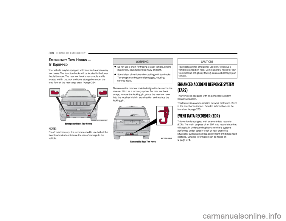
Your vehicle may be equipped with front and rear recovery
tow hooks. The front tow hooks will be located in the lower
fascia/bumper. The rear tow hook is removable and is
located within the jack and tools storage bin under the
load floor of the rear cargo area
Úpage 294.
Emergency Front Tow Hooks
NOTE:For off road recovery, it is recommended to use both of the
front tow hooks to minimize the risk of damage to the
vehicle. The removable rear tow hook is designed to be used in the
receiver hitch as a recovery option. For rear tow hook
usage, remove the locking pin, place the rear tow hook
into the receiver hitch in any direction and replace the
locking pin.
Removable Rear Tow Hook
ENHANCED ACCIDENT RESPONSE SYSTEM
(EARS)
This vehicle is equipped with an Enhanced Accident
Response System.
This feature is a communication network that takes effect
in the event of an impact. Detailed information can be
found on
Úpage 273.
EVENT DATA RECORDER (EDR)
This vehicle is equipped with an event data recorder
(EDR). The main purpose of an EDR is to record data that
will assist in understanding how a vehicle’s systems
performed under certain crash or near crash-like
situations, such as an air bag deployment or hitting a road
obstacle. Detailed information can be found on
Úpage 274.
WARNING!
Do not use a chain for freeing a stuck vehicle. Chains
may break, causing serious injury or death.
Stand clear of vehicles when pulling with tow hooks.
Tow straps may become disengaged, causing
serious injury.
CAUTION!
Tow hooks are for emergency use only, to rescue a
vehicle stranded off road. Do not use tow hooks for tow
truck hookup or highway towing. You could damage your
vehicle.
23_WS_OM_EN_USC_t.book Page 308
Page 311 of 396
309
SERVICING AND MAINTENANCE
SCHEDULED SERVICING
Your vehicle is equipped with an automatic oil change
indicator system. The oil change indicator system will
remind you that it is time to take your vehicle in for
scheduled maintenance.
Based on engine operation conditions, the oil change
indicator message will illuminate. This means that service
is required for your vehicle. Operating conditions such as
frequent short-trips, trailer tow, extremely hot or cold
ambient temperatures, and extended idling will influence
when the “Oil Change Required” message is displayed.
Have your vehicle serviced as soon as possible, within the
next 500 miles (805 km).An authorized dealer will reset the oil change indicator
message after completing the scheduled oil change or for
engine oil life reset procedure Úpage 101.
NOTE:3.0L & 5.7L Engines:
Under no circumstances should oil
change intervals exceed 10,000 miles (16,000 km), or
12 months, whichever comes first. The engine controller
also monitors the number of hours of engine run time, and
will illuminate the oil change indicator after 350 hours
(which is not likely to be exceeded except for certain fleet
customers with extended engine idling periods).
6.4L Engines: Under no circumstances should oil change
intervals exceed 6,000 miles (10,000 km), or 6 months,
whichever comes first. The engine controller also monitors
the number of hours of engine run time, and will illuminate
the oil change indicator after 350 hours (which is not likely
to be exceeded except for certain fleet customers with
extended engine idling periods). Once A Month Or Before A Long Trip:
Check engine oil level
Check windshield washer fluid level
Check the tire inflation pressures and look for unusual
wear or damage
Check the fluid levels of the coolant reservoir, brake
master cylinder and fill as needed.
Check function of all interior and exterior lights
8
23_WS_OM_EN_USC_t.book Page 309
Page 313 of 396

SERVICING AND MAINTENANCE311
Inspect the front and rear axle fluid, change if
using your vehicle for police, taxi, fleet, off-road
or frequent trailer towing. X
X X XX XX
Inspect the brake linings, parking brake
function. X
X X XX XX
Inspect transfer case fluid. XX XXX
Additional Maintenance
Replace engine air cleaner filter. XX XXX
Replace the cabin air filter. To be replaced every 12,000 miles (19,000 km).
Replace spark plugs (3.0L Engine).
1X X Replace spark plugs (5.7L Engine).
1
X Replace spark plugs (6.4L Engine).
1
X
Flush and replace the engine coolant at
10 years or 150,000 miles (240,000 km)
whichever comes first. X
X
Mileage Or Time Passed (Whichever
Comes First)
20,000
30,000
40,000
50,000
60,000
70,000
80,000
90,000
100,000
110,000
120,000
130,000
140,000
150,000
Or Years: 2 3 4 5 6 7 8 9 10 11 12 13 14 15
Or Kilometers:
32,000
48,000
64,000
80,000
96,000
112,000
128,000
144,000
160,000
176,000
192,000
208,000
224,000
240,000
8
23_WS_OM_EN_USC_t.book Page 311
Page 319 of 396
SERVICING AND MAINTENANCE317
NOTE:
After adding oil to the engine, always reinstall the oil
cap securely by rotating clockwise until it stops. Never
run the engine without the oil fill cap as this could
cause an oil leak.
Because the oil level is automatically detected only
when the engine has been off and restarted (after four
minutes), the system cannot immediately detect a
sudden drop in oil level while driving (for example, if the
oil pan starts to leak due to damage during an off-road
event).
CHECKING OIL LEVEL — 5.7L & 6.4L
E
NGINES
To ensure proper engine lubrication, the engine oil must
be maintained at the correct level. Check the oil level at
regular intervals, such as every fuel stop. The best time to
check the engine oil level is about five minutes after a fully
warmed up engine is shut off.
Checking the oil while the vehicle is on level ground will
improve the accuracy of the oil level readings.
There are four possible dipstick types:
Crosshatched zone.
Crosshatched zone marked SAFE.
Crosshatched zone marked with MIN at the low end of
the range and MAX at the high end of the range.
Crosshatched zone marked with dimples at the MIN
and the MAX ends of the range.
NOTE:Always maintain the oil level within the crosshatch
markings on the dipstick.
Adding 1 qt (1 L) of oil when the reading is at the low end
of the dipstick range will raise the oil level to the high end
of the range marking.
ADDING WASHER FLUID
The instrument cluster display will indicate when the
washer fluid level is low. When the sensor detects a low
fluid level, the Low Washer Fluid Warning Light will turn on
and the "Washer Fluid Low" message will be displayed.
The fluid reservoir for the windshield washers and the rear
window washer is shared. The fluid reservoir is located in
the engine compartment, be sure to check the fluid level
at regular intervals. Fill the reservoir with windshield
washer solvent only (not radiator antifreeze). When
refilling the washer fluid reservoir, take some washer fluid
and apply it to a cloth or towel and wipe clean the wiper
blades, this will help blade performance. To prevent
freeze-up of your windshield washer system in cold
weather, select a solution or mixture that meets or
exceeds the temperature range of your climate. This rating
information can be found on most washer fluid containers.
NOTE:Use care when filling under hood fluids such as engine oil,
washer fluid, antifreeze, etc. to minimize spillage onto top
of engine. Any excess fluid that is spilled onto the top of
the engine should be removed using compressed air or an
absorbent cloth.
CAUTION!
If the “Critically Low or Critically High” Oil Level Warning
Light is illuminated, the following steps should be
taken:
Critically Low: add two quarts of manufacturer speci -
fied oil as soon as possible
Úpage 376. Continuing
to operate the vehicle with “Critically Low” oil level
may damage the engine.
Critically High: contact an authorized dealer for
service. Continuing to operate the vehicle with “Criti -
cally High” oil level may damage the engine.
Do not use any oils that are not manufacturer specified
and API approved.
Used engine oil and oil filters contain substances which
are harmful to the environment. When oil and filters are
changed contact an authorized dealer and dispose of in
a safe and responsible manner.
WARNING!
Commercially available windshield washer solvents are
flammable. They could ignite and burn you. Care must
be exercised when filling or working around the washer
solution.
8
23_WS_OM_EN_USC_t.book Page 317
Page 323 of 396
SERVICING AND MAINTENANCE321
Refrigerant Recovery And Recycling —
R–1234yf
R–1234yf Air Conditioning Refrigerant is a Hydrofluo -
roolefin (HFO) that is endorsed by the Environmental
Protection Agency and is an ozone-friendly substance with
a low global-warming potential. The manufacturer
recommends that air conditioning service be performed by
an authorized dealer using recovery and recycling
equipment.
NOTE:Use only manufacturer approved A/C system PAG
compressor oil, and refrigerants.
Cabin Air Filter Replacement
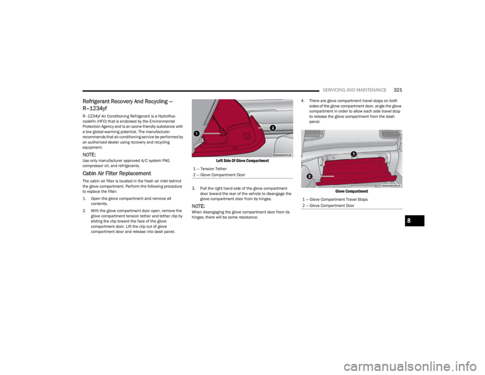
The cabin air filter is located in the fresh air inlet behind
the glove compartment. Perform the following procedure
to replace the filter:
1. Open the glove compartment and remove all contents.
2. With the glove compartment door open, remove the glove compartment tension tether and tether clip by
sliding the clip toward the face of the glove
compartment door. Lift the clip out of glove
compartment door and release into dash panel.
Left Side Of Glove Compartment
3. Pull the right hand side of the glove compartment door toward the rear of the vehicle to disengage the
glove compartment door from its hinges.
NOTE:When disengaging the glove compartment door from its
hinges, there will be some resistance. 4. There are glove compartment travel stops on both
sides of the glove compartment door, angle the glove
compartment in order to allow each side travel stop
to release the glove compartment from the dash
panel.
Glove Compartment
1 — Tension Tether
2 — Glove Compartment Door
1 — Glove Compartment Travel Stops
2 — Glove Compartment Door
8
23_WS_OM_EN_USC_t.book Page 321
Page 324 of 396
322SERVICING AND MAINTENANCE
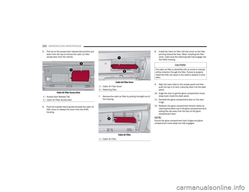
5. Pull out on the access door release tab and then pull
down from the top to remove the cabin air filter
access door from the vehicle.
Cabin Air Filter Access Door
6. Push the outside retaining tabs towards the cabin air filter cover to release the cover from the HVAC
housing.
Cabin Air Filter Cover
7. Remove the cabin air filter by pulling it straight out of the housing.
Cabin Air Filter
8. Install the cabin air filter with the arrow on the filter pointing toward the floor. When installing the filter
cover, make sure the retaining tabs fully engage into
the HVAC housing.
9. Align the lower tabs on the access panel and then push the top in to lock it securely back into the dash
panel.
10. Angle the door to get the glove compartment travel stops back inside the dash panel.
11. Reinstall the glove compartment door on the door hinge.
12. Reattach the glove compartment tension tether by inserting the tether clip in the glove compartment and
sliding the clip away from the face of the glove
compartment door.
NOTE:Ensure the glove compartment door hinges and glove
compartment travel stops are fully engaged.
1 — Access Door Release Tab
2 — Cabin Air Filter Access Door
1 — Cabin Air Filter Cover
2 — Retaining Tabs
1 — Cabin Air Filter
CAUTION!
The cabin air filter is identified with an arrow to indicate
airflow direction through the filter. Failure to properly
install the filter will result in the need to replace it more
often.
23_WS_OM_EN_USC_t.book Page 322
Page 328 of 396

326SERVICING AND MAINTENANCE
To minimize the possibility of catalytic converter damage:
Do not interrupt the ignition when the transmission is
in gear and the vehicle is in motion.
Do not try to start the vehicle by pushing or towing the
vehicle.
Do not idle the engine with any ignition components
disconnected or removed, such as when diagnostic
testing, or for prolonged periods during very rough idle
or malfunctioning operating conditions.
COOLING SYSTEM
Engine Coolant Checks
Check the engine coolant (antifreeze) protection every
12 months (before the onset of freezing weather, where
applicable). If the engine coolant is dirty, the system
should be drained, flushed, and refilled with fresh Organic
Additive Technology (OAT) coolant (conforming to
MS.90032) by an authorized dealer. Check the front of the
A/C condenser for any accumulation of bugs, leaves, etc.
If dirty, clean by gently spraying water from a garden hose
vertically down the face of the condenser.
Check the engine cooling system hoses for brittle rubber,
cracking, tears, cuts, and tightness of the connection at
the coolant recovery bottle and radiator. Inspect the entire
system for leaks. DO NOT REMOVE THE COOLANT
PRESSURE CAP WHEN THE COOLING SYSTEM IS HOT.
Cooling System — Drain, Flush And Refill
NOTE:Some vehicles require special tools to add coolant
properly. Failure to fill these systems properly could lead
to severe internal engine damage. If any coolant is needed
to be added to the system please contact an authorized
dealer.
If the engine coolant (antifreeze) is dirty or contains visible
sediment, have an authorized dealer clean and flush with
Organic Additive Technology (OAT) coolant (conforming to
MS.90032).
For the proper maintenance intervals
Úpage 310.
Selection Of Coolant
Refer to Engine Fluids And Lubricants Úpage 376.
NOTE:
Mixing of engine coolant (antifreeze) other than speci-
fied Organic Additive Technology (OAT) engine coolant,
may result in engine damage and may decrease corro -
sion protection. OAT engine coolant is different and
should not be mixed with Hybrid Organic Additive Tech -
nology (HOAT) engine coolant or any “globally compat -
ible” coolant. If a non-OAT engine coolant is introduced
into the cooling system in an emergency, the cooling
system will need to be drained, flushed, and refilled
with fresh OAT coolant (conforming to MS.90032), by
an authorized dealer as soon as possible.
Do not use water alone or alcohol-based engine
coolant products. Do not use additional rust inhibitors
or antirust products, as they may not be compatible
with the radiator engine coolant and may plug the radi -
ator.
This vehicle has not been designed for use with
propylene glycol-based engine coolant. Use of
propylene glycol-based engine coolant is not recom -
mended.
Some vehicles require special tools to add coolant
properly. Failure to fill these systems properly could
lead to severe internal engine damage. If any coolant is
needed to be added to the system please contact an
authorized dealer.
WARNING!
You or others can be badly burned by hot engine
coolant (antifreeze) or steam from your radiator. If
you see or hear steam coming from under the hood,
do not open the hood until the radiator has had time
to cool. Never open a cooling system pressure cap
when the radiator or coolant bottle is hot.
Keep hands, tools, clothing, and jewelry away from
the radiator cooling fan when the hood is raised. The
fan starts automatically and may start at any time,
whether the engine is running or not.
When working near the radiator cooling fan, discon -
nect the fan motor lead or turn the ignition to the OFF
position. The fan is temperature controlled and can
start at any time the ignition is in the ON position.
23_WS_OM_EN_USC_t.book Page 326
Page 341 of 396
SERVICING AND MAINTENANCE339
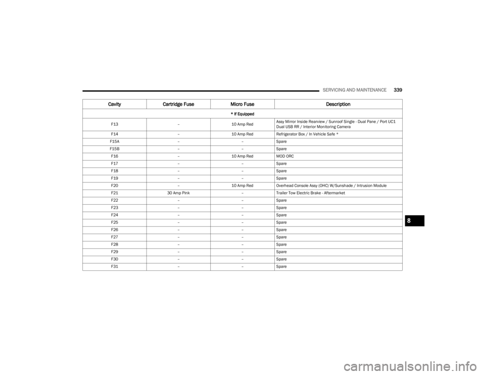
F13 –10 Amp RedAssy Mirror Inside Rearview / Sunroof Single - Dual Pane / Port UC1
Dual USB RR / Interior Monitoring Camera
F14 –10 Amp RedRefrigerator Box / In Vehicle Safe *
F15A ––Spare
F15B ––Spare
F16 –10 Amp RedMOD ORC
F17 ––Spare
F18 ––Spare
F19 ––Spare
F20 –10 Amp RedOverhead Console Assy (OHC) W/Sunshade / Intrusion Module
F21 30 Amp Pink –Trailer Tow Electric Brake - Aftermarket
F22 ––Spare
F23 ––Spare
F24 ––Spare
F25 ––Spare
F26 ––Spare
F27 ––Spare
F28 ––Spare
F29 ––Spare
F30 ––Spare
F31 ––Spare
Cavity Cartridge Fuse Micro Fuse Description
* If Equipped
8
23_WS_OM_EN_USC_t.book Page 339
Page 347 of 396
SERVICING AND MAINTENANCE345
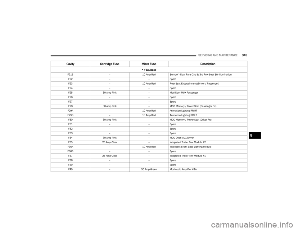
F21B –10 Amp RedSunroof - Dual Pane 2nd & 3rd Row Seat SW-Illumination
F22 ––Spare
F23 –10 Amp RedRear Seat Entertainment (Driver / Passenger)
F24 ––Spare
F25 30 Amp Pink –Mod Door MUX Passenger
F26 ––Spare
F27 ––Spare
F28 30 Amp Pink –MOD Memory / Power Seat (Passenger Frt)
F29A –10 Amp RedAnimation Lighting RR-RT
F29B –10 Amp RedAnimation Lighting RR-LT
F30 30 Amp Pink –MOD Memory / Power Seat (Driver Frt)
F31 ––Spare
F32 ––Spare
F33 ––Spare
F34 30 Amp Pink –MOD Door MUX Driver
F35 25 Amp Clear –Integrated Trailer Tow Module #2
F36A –10 Amp RedIntelligent Event Base Lighting Module
F36B ––Spare
F37 25 Amp Clear –Integrated Trailer Tow Module #1
F38 ––Spare
F39 ––Spare
F40 –30 Amp Green Mod Audio Amplifier #1A
CavityCartridge Fuse Micro Fuse Description
* If Equipped
8
23_WS_OM_EN_USC_t.book Page 345