tow JEEP WAGONEER 2023 Owner's Manual
[x] Cancel search | Manufacturer: JEEP, Model Year: 2023, Model line: WAGONEER, Model: JEEP WAGONEER 2023Pages: 396, PDF Size: 15.17 MB
Page 90 of 396
88GETTING TO KNOW YOUR VEHICLE
NOTE:The activation zone is the same for vehicles equipped with
or without a trailer tow package.
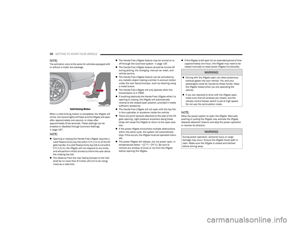
Valid Kicking Motion
When a valid kicking motion is completed, the liftgate will
chime, the hazard lights will flash and the liftgate will open
after approximately one second, or close after
approximately three seconds. These settings can be
enabled or disabled through Uconnect Settings
Úpage 197.
NOTE:
Opening or closing the Hands-Free Liftgate requires a
valid Passive Entry key fob within 5 ft (1.5 m) of the lift -
gate handle. If a valid Passive Entry key fob is not within
5 ft (1.5 m), the liftgate will not respond to any kicks,
and will perform inhibit chimes to inform the user about
the missing key fob.
The distance from the rear fascia/bumper to the foot
shall be no more than 8 inches (20 cm) to be recog -
nized as a valid kick.
The Hands-Free Liftgate feature may be turned on or
off through the Uconnect system
Úpage 197.
The Hands-Free Liftgate feature should be turned off
during jacking, tire changing, manual car wash, and
vehicle service.
The Hands-Free Liftgate feature can be activated by
any metallic object making a similar in-and-out motion
under the rear fascia/bumper, such as cleaning using
a metal broom.
The Hands-Free Liftgate will only operate when the
transmission is in PARK.
If anything obstructs the Hands-Free Liftgate while it is
opening or closing, the liftgate will automatically
reverse to the closed/open position, provided it meets
sufficient resistance.
The Hands-Free Liftgate will not open with the key fob
in the cupholder or anywhere inside the vehicle.
There are pinch sensors attached to the side of the lift -
gate opening. Light pressure anywhere along these
strips will cause the liftgate to return to the open posi -
tion.
If the power liftgate encounters multiple obstructions
within the same cycle, the system will automatically
stop. If this occurs, the liftgate must be operated manu -
ally.
The power liftgate will release, but not power open, in
temperatures below −12°F (−24°C). Be sure to
remove any buildup of snow or ice from the liftgate
before opening the liftgate.
If the liftgate is left open for an extended period of time
(approximately one hour), the liftgate may need to be
closed manually to reset power liftgate functionality.
NOTE:Allow the power system to open the liftgate. Manually
pushing or pulling the liftgate may activate the liftgate
obstacle detection feature and stop the power operation
or reverse its direction.
WARNING!
Driving with the liftgate open can allow poisonous
exhaust gases into your vehicle. You and your
passengers could be injured by these fumes. Keep
the liftgate closed when you are operating the
vehicle.
If you are required to drive with the liftgate open,
make sure that all windows are closed, and the
climate control blower switch is set at high speed.
Do not use the recirculation mode.
WARNING!
During power operation, personal injury or cargo
damage may occur. Ensure the liftgate travel path is
clear. Make sure the liftgate is closed and latched
before driving away.
23_WS_OM_EN_USC_t.book Page 88
Page 93 of 396
GETTING TO KNOW YOUR VEHICLE91
Retractable Cargo Area Cover —
If Equipped
The purpose of this cover is for privacy, not to secure
loads. It will not prevent cargo from shifting or protect
passengers from loose cargo.
To cover the cargo area:
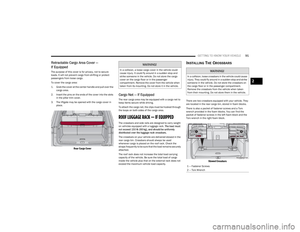
1. Grab the cover at the center handle and pull over the
cargo area.
2. Insert the pins on the ends of the cover into the slots in the pillar trim cover.
3. The liftgate may be opened with the cargo cover in place.
Rear Cargo Cover
Cargo Net — If Equipped
The rear cargo area may be equipped with a cargo net to
keep items secure while driving.
To attach the cargo net, the clips must be hooked through
the loops on both sides of the cargo area.
ROOF LUGGAGE RACK — IF EQUIPPED
The crossbars and side rails are designed to carry weight
on vehicles equipped with a luggage rack. The load must
not exceed 150 lb (68 kg), and should be uniformly
distributed over the luggage rack crossbars.
The crossbars on your vehicle are delivered stowed in the
rear cargo bin. Crossbars should always be used
whenever cargo is placed on the roof rack. Check the
straps frequently to be sure that the load remains securely
attached.
The roof rack does not increase the total load carrying
capacity of the vehicle. Be sure the total load of cargo
inside the vehicle plus that on the external rack does not
exceed the maximum vehicle load capacity.
INSTALLING THE CROSSBARS
There are two crossbars equipped with your vehicle. They
are located in the rear cargo bin, stored in foam blocks.
There is also a packet of fastener screws and a Torx
wrench provided in the foam blocks. You can find the
packet of fastener screws in the left foam block and the
Torx wrench in the right foam block.
Stowed Crossbars
WARNING!
In a collision, a loose cargo cover in the vehicle could
cause injury. It could fly around in a sudden stop and
strike someone in the vehicle. Do not store the cargo
cover on the cargo floor or in the passenger
compartment. Remove the cover from the vehicle when
taken from its mounting. Do not store it in the vehicle.WARNING!
In a collision, loose crossbars in the vehicle could cause
injury. They could fly around in a sudden stop and strike
someone in the vehicle. Do not store the crossbars on
the cargo floor or in the passenger compartment.
Remove the crossbars from the vehicle when taken
from their mounting. Do not store them in the vehicle.
1 — Fastener Screws
2 — Torx Wrench
2
23_WS_OM_EN_USC_t.book Page 91
Page 94 of 396
92GETTING TO KNOW YOUR VEHICLE
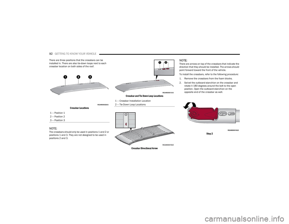
There are three positions that the crossbars can be
installed in. There are also tie-down loops next to each
crossbar location on both sides of the roof.
Crossbar Locations
NOTE:The crossbars should only be used in positions 1 and 2 or
positions 1 and 3. They are not designed to be used in
positions 2 and 3.
Crossbar and Tie Down Loop Locations
Crossbar Directional Arrow
NOTE:There are arrows on top of the crossbars that indicate the
direction that they should be installed. The arrows should
point forward toward the front of the vehicle.
To install the crossbars, refer to the following procedure:
1. Remove the crossbars from the foam blocks.
2. Swivel the outboard stanchion on the crossbar and rotate it 180 degrees around the bolt to the open
position. Open the outboard stanchion on the
opposite end of the crossbar as well.
Step 2
1 — Position 1
2 — Position 2
3 — Position 3
1 — Crossbar Installation Location
2 — Tie-Down Loop Locations
23_WS_OM_EN_USC_t.book Page 92
Page 97 of 396
GETTING TO KNOW YOUR VEHICLE95
REMOVING THE CROSSBARS
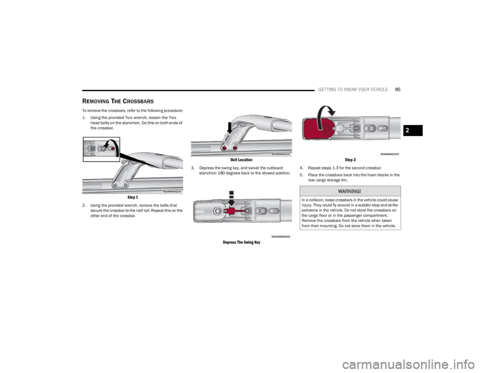
To remove the crossbars, refer to the following procedure:
1. Using the provided Torx wrench, loosen the Torx
head bolts on the stanchion. Do this on both ends of
the crossbar.
Step 1
2. Using the provided wrench, remove the bolts that secure the crossbar to the roof rail. Repeat this on the
other end of the crossbar.
Bolt Location
3. Depress the swing key, and swivel the outboard stanchion 180 degrees back to the stowed position.
Depress The Swing Key Step 3
4. Repeat steps 1-3 for the second crossbar.
5. Place the crossbars back into the foam blocks in the
rear cargo storage bin.
WARNING!
In a collision, loose crossbars in the vehicle could cause
injury. They could fly around in a sudden stop and strike
someone in the vehicle. Do not store the crossbars on
the cargo floor or in the passenger compartment.
Remove the crossbars from the vehicle when taken
from their mounting. Do not store them in the vehicle.
2
23_WS_OM_EN_USC_t.book Page 95
Page 99 of 396
GETTING TO KNOW YOUR INSTRUMENT PANEL97
Use this QR code to access your digital
experience.
INSTRUMENT CLUSTER
D
ESCRIPTIONS
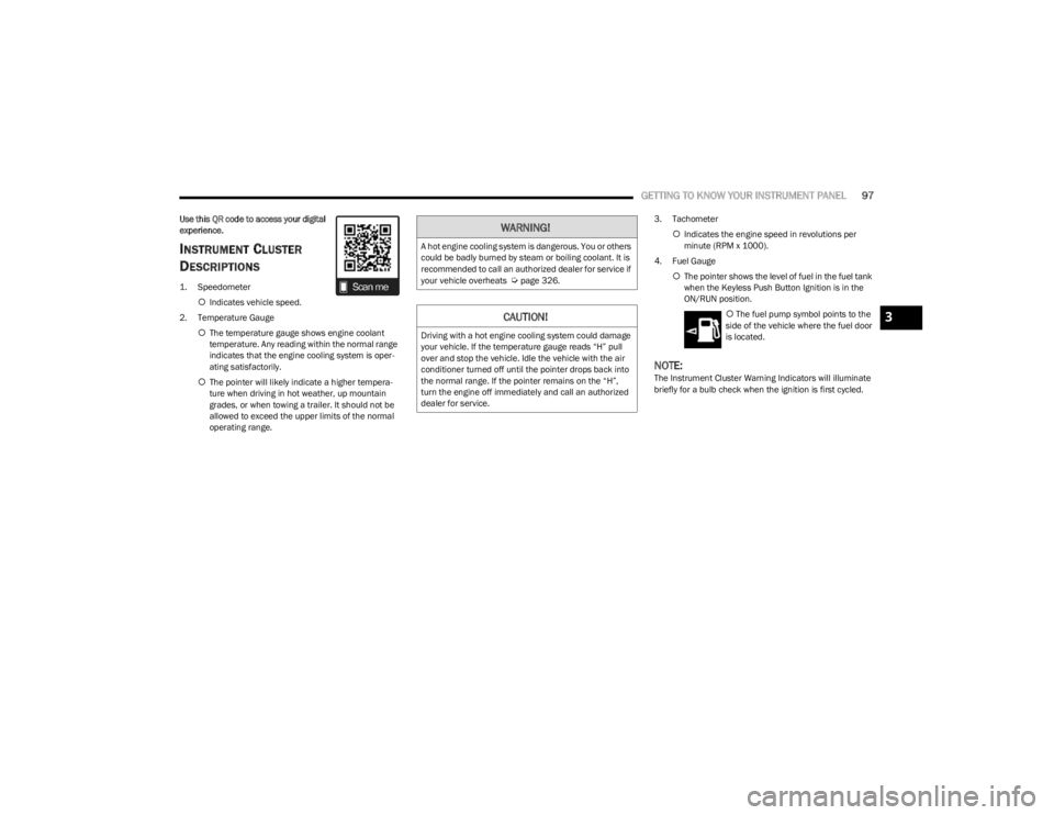
1. Speedometer
Indicates vehicle speed.
2. Temperature Gauge The temperature gauge shows engine coolant
temperature. Any reading within the normal range
indicates that the engine cooling system is oper -
ating satisfactorily.
The pointer will likely indicate a higher tempera -
ture when driving in hot weather, up mountain
grades, or when towing a trailer. It should not be
allowed to exceed the upper limits of the normal
operating range. 3. Tachometer
Indicates the engine speed in revolutions per
minute (RPM x 1000).
4. Fuel Gauge The pointer shows the level of fuel in the fuel tank
when the Keyless Push Button Ignition is in the
ON/RUN position.
The fuel pump symbol points to the
side of the vehicle where the fuel door
is located.
NOTE:The Instrument Cluster Warning Indicators will illuminate
briefly for a bulb check when the ignition is first cycled.
WARNING!
A hot engine cooling system is dangerous. You or others
could be badly burned by steam or boiling coolant. It is
recommended to call an authorized dealer for service if
your vehicle overheats
Úpage 326.
CAUTION!
Driving with a hot engine cooling system could damage
your vehicle. If the temperature gauge reads “H” pull
over and stop the vehicle. Idle the vehicle with the air
conditioner turned off until the pointer drops back into
the normal range. If the pointer remains on the “H”,
turn the engine off immediately and call an authorized
dealer for service.
3
23_WS_OM_EN_USC_t.book Page 97
Page 101 of 396
GETTING TO KNOW YOUR INSTRUMENT PANEL99
INSTRUMENT CLUSTER DESCRIPTIONS
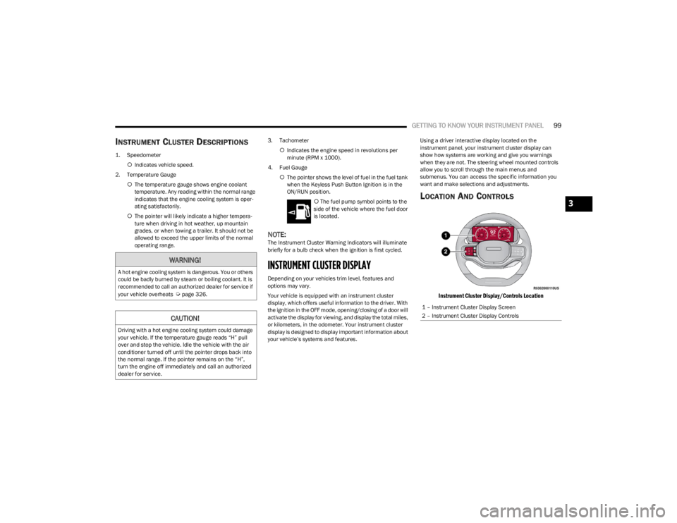
1. Speedometer
Indicates vehicle speed.
2. Temperature Gauge The temperature gauge shows engine coolant
temperature. Any reading within the normal range
indicates that the engine cooling system is oper -
ating satisfactorily.
The pointer will likely indicate a higher tempera -
ture when driving in hot weather, up mountain
grades, or when towing a trailer. It should not be
allowed to exceed the upper limits of the normal
operating range. 3. Tachometer
Indicates the engine speed in revolutions per
minute (RPM x 1000).
4. Fuel Gauge The pointer shows the level of fuel in the fuel tank
when the Keyless Push Button Ignition is in the
ON/RUN position.
The fuel pump symbol points to the
side of the vehicle where the fuel door
is located.
NOTE:The Instrument Cluster Warning Indicators will illuminate
briefly for a bulb check when the ignition is first cycled.
INSTRUMENT CLUSTER DISPLAY
Depending on your vehicles trim level, features and
options may vary.
Your vehicle is equipped with an instrument cluster
display, which offers useful information to the driver. With
the ignition in the OFF mode, opening/closing of a door will
activate the display for viewing, and display the total miles,
or kilometers, in the odometer. Your instrument cluster
display is designed to display important information about
your vehicle’s systems and features. Using a driver interactive display located on the
instrument panel, your instrument cluster display can
show how systems are working and give you warnings
when they are not. The steering wheel mounted controls
allow you to scroll through the main menus and
submenus. You can access the specific information you
want and make selections and adjustments.
LOCATION AND CONTROLS
Instrument Cluster Display/Controls Location
WARNING!
A hot engine cooling system is dangerous. You or others
could be badly burned by steam or boiling coolant. It is
recommended to call an authorized dealer for service if
your vehicle overheats
Úpage 326.
CAUTION!
Driving with a hot engine cooling system could damage
your vehicle. If the temperature gauge reads “H” pull
over and stop the vehicle. Idle the vehicle with the air
conditioner turned off until the pointer drops back into
the normal range. If the pointer remains on the “H”,
turn the engine off immediately and call an authorized
dealer for service.
1 – Instrument Cluster Display Screen
2 – Instrument Cluster Display Controls
3
23_WS_OM_EN_USC_t.book Page 99
Page 103 of 396
GETTING TO KNOW YOUR INSTRUMENT PANEL101
Navigate Left or Right to highlight desired tile
Press OK to select the tile and navigate to the selected
submenu and press OK again to add your selection to
your tile view
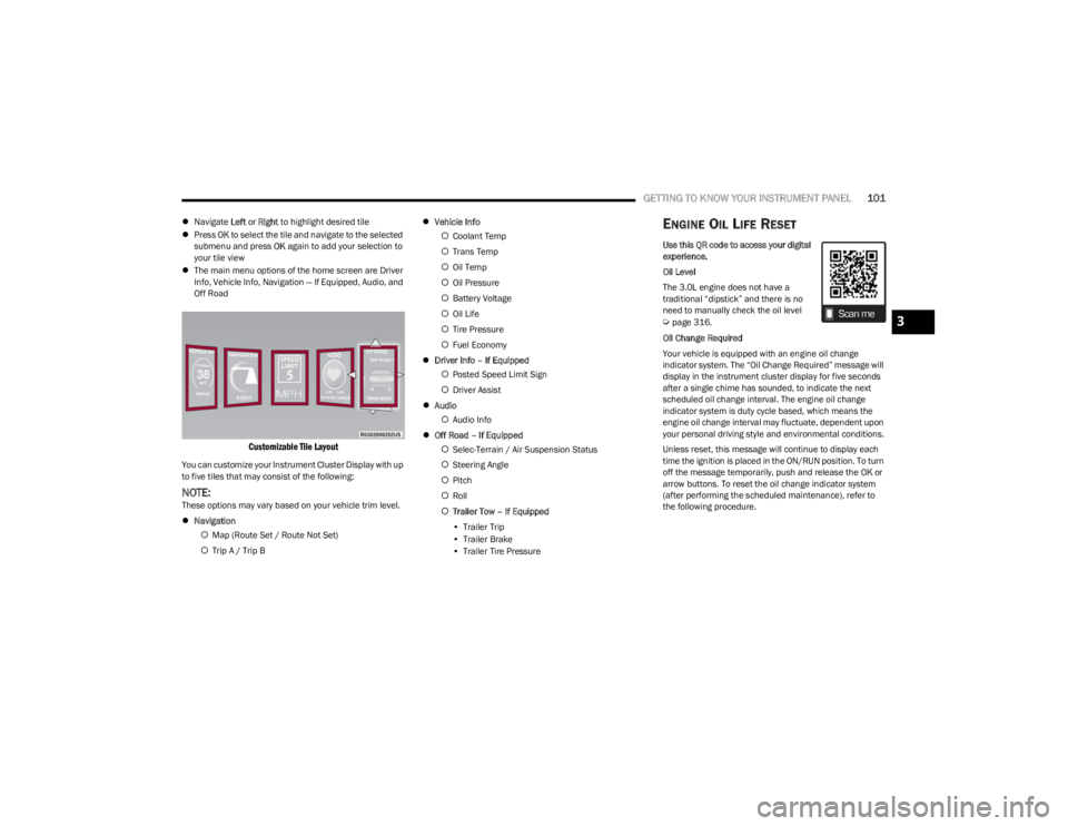
The main menu options of the home screen are Driver
Info, Vehicle Info, Navigation — If Equipped, Audio, and
Off Road
Customizable Tile Layout
You can customize your Instrument Cluster Display with up
to five tiles that may consist of the following:
NOTE:These options may vary based on your vehicle trim level.
Navigation
Map (Route Set / Route Not Set)
Trip A / Trip B
Vehicle Info
Coolant Temp
Trans Temp
Oil Temp
Oil Pressure
Battery Voltage
Oil Life
Tire Pressure
Fuel Economy
Driver Info – If Equipped
Posted Speed Limit Sign
Driver Assist
Audio
Audio Info
Off Road – If Equipped
Selec-Terrain / Air Suspension Status
Steering Angle
Pitch
Roll
Trailer Tow – If Equipped
• Trailer Trip
• Trailer Brake
• Trailer Tire Pressure
ENGINE OIL LIFE RESET
Use this QR code to access your digital
experience.
Oil Level
The 3.0L engine does not have a
traditional “dipstick” and there is no
need to manually check the oil level
Úpage 316.
Oil Change Required
Your vehicle is equipped with an engine oil change
indicator system. The “Oil Change Required” message will
display in the instrument cluster display for five seconds
after a single chime has sounded, to indicate the next
scheduled oil change interval. The engine oil change
indicator system is duty cycle based, which means the
engine oil change interval may fluctuate, dependent upon
your personal driving style and environmental conditions.
Unless reset, this message will continue to display each
time the ignition is placed in the ON/RUN position. To turn
off the message temporarily, push and release the OK or
arrow buttons. To reset the oil change indicator system
(after performing the scheduled maintenance), refer to
the following procedure.3
23_WS_OM_EN_USC_t.book Page 101
Page 107 of 396
GETTING TO KNOW YOUR INSTRUMENT PANEL105
TRIP
Push and release the up or down arrow button
until the Trip menu title is displayed in the instrument
cluster display. Toggle the left or right arrow button
to select Trip A or Trip B. The Trip information will display
the following:
Distance – Shows the total distance (mi or km) traveled
for Trip A or Trip B since the last reset.
Average Fuel Economy – Shows the average fuel
economy (MPG or L/100 km or km/L) of Trip A or Trip
B since the last reset.
Elapsed Time – Shows the total elapsed time of travel
since Trip A or Trip B has been reset.
Hold the OK button to reset feature information.
NAVIGATION — IF EQUIPPED
Push and release the left or right arrow button until
the Navigation display icon/title is highlighted in the
instrument cluster display.
“Hold OK to Start Route” will display when no active
route is set.
“Hold OK to Cancel Route” will display when an active
route is set.
OFF ROAD
Push and release the up or down arrow button
until the Off Road Menu icon/title is highlighted. Push the
left or right arrow button to scroll the submenus.
Terrain Status
Selec-Terrain Status
Air Suspension Status
Vehicle Dynamics
Wheel Articulation
Transfer Case Status
Steering Angle
Pitch And Roll
Vehicle Pitch
Vehicle Roll
TRAILER TOW — IF EQUIPPED
Push and release the up or down arrow button
until the Trailer Tow Menu icon/title is highlighted in the
instrument cluster display. Push and release the left or
right arrow button to select Trailer Trip or Trailer Brake.
Trailer Trip will display the following:
Distance
NOTE:Press and hold the OK button to reset all the information. Trailer Brake will display the following:
Output
Type
Gain
AUDIO
Push and release the up or down arrow button
until the Audio Menu icon/title is highlighted in the
instrument cluster display. This menu will display the
audio source information, including the Song name, Artist
name, and audio source with an accompanying graphic.
MESSAGES
Push and release the up or down arrow button
until the Messages Menu item is highlighted. This feature
shows the number of stored warning messages. Pushing
the left or right arrow button will allow you to see
what the stored messages are.
When no messages are present, main menu icon will be a
closed envelope.
SETTINGS
NOTE:
If current theme is set to Digital, tachometer will not
display while in the Settings menu.
NOTE:If your vehicle is equipped with Head Up Display (HUD),
feature settings are available at any vehicle speed
Úpage 106.
3
23_WS_OM_EN_USC_t.book Page 105
Page 108 of 396
106GETTING TO KNOW YOUR INSTRUMENT PANEL
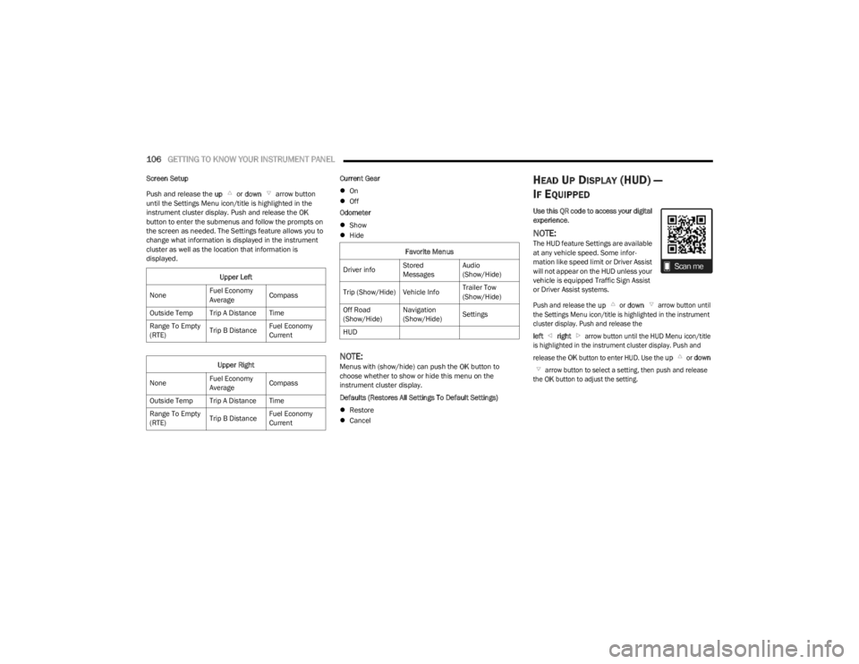
Screen Setup
Push and release the up or down arrow button
until the Settings Menu icon/title is highlighted in the
instrument cluster display. Push and release the OK
button to enter the submenus and follow the prompts on
the screen as needed. The Settings feature allows you to
change what information is displayed in the instrument
cluster as well as the location that information is
displayed. Current Gear
On
Off
Odometer
Show
Hide
NOTE:Menus with (show/hide) can push the OK button to
choose whether to show or hide this menu on the
instrument cluster display.
Defaults (Restores All Settings To Default Settings)
Restore
Cancel
HEAD UP DISPLAY (HUD) —
I
F EQUIPPED
Use this QR code to access your digital
experience .
NOTE:The HUD feature Settings are available
at any vehicle speed. Some infor -
mation like speed limit or Driver Assist
will not appear on the HUD unless your
vehicle is equipped Traffic Sign Assist
or Driver Assist systems.
Push and release the
up
or
down
arrow button until
the Settings Menu icon/title is highlighted in the instrument
cluster display. Push and release the
left
right
arrow button until the HUD Menu icon/title
is highlighted in the instrument cluster display. Push and
release the
OK
button to enter HUD. Use the
up
or
down
arrow button to select a setting, then push and release
the
OK
button to adjust the setting.
Upper Left
None Fuel Economy
AverageCompass
Outside Temp Trip A Distance Time
Range To Empty
(RTE) Trip B DistanceFuel Economy
Current
Upper Right
None Fuel Economy
AverageCompass
Outside Temp Trip A Distance Time
Range To Empty
(RTE) Trip B DistanceFuel Economy
CurrentFavorite Menus
Driver info Stored
MessagesAudio
(Show/Hide)
Trip (Show/Hide) Vehicle Info Trailer Tow
(Show/Hide)
Off Road
(Show/Hide) Navigation
(Show/Hide)
Settings
HUD
23_WS_OM_EN_USC_t.book Page 106
Page 110 of 396
108GETTING TO KNOW YOUR INSTRUMENT PANEL
When load reduction is activated, the message “Battery
Saver On” or “Battery Saver Mode” will appear in the
instrument cluster.
These messages indicate the vehicle battery has a low
state of charge and continues to lose electrical charge at
a rate that the charging system cannot sustain.
NOTE:
The charging system is independent from load reduc -
tion. The charging system performs a diagnostic on the
charging system continuously.
If the Battery Charge Warning Light is on it may indicate
a problem with the charging system
Úpage 109.
The electrical loads that may be switched off (if equipped),
and vehicle functions which can be affected by load
reduction:
Heated Seat/Vented Seats/Heated Wheel
Rear Defroster And Heated Mirrors
HVAC System
115 Volt AC Power Inverter System
Audio and Telematics System
Loss of the battery charge may indicate one or more of the
following conditions:
The charging system cannot deliver enough electrical
power to the vehicle system because the electrical
loads are larger than the capability of the charging
system. The charging system is still functioning
properly.
Turning on all possible vehicle electrical loads (e.g.
HVAC to max settings, exterior and interior lights, over -
loaded power outlets +12 Volt, 115 Volt AC, USB ports)
during certain driving conditions (city driving, towing,
frequent stopping, etc.).
Installing options like additional lights, upfitter elec -
trical accessories, audio systems, alarms and similar
devices.
Unusual driving cycles (short trips separated by long
parking periods).
The vehicle was parked for an extended period of time
(weeks, months).
The battery was recently replaced and was not charged
completely.
The battery was discharged by an electrical load left on
when the vehicle was parked.
The battery was used for an extended period with the
engine not running to supply radio, lights, chargers,
+12 Volt portable appliances like vacuum cleaners,
game consoles and similar devices.
What to do when an electrical load reduction action
message is present (“Battery Saver On” or “Battery Saver
Mode”)
During a trip:
Reduce power to unnecessary loads if possible:
Turn off redundant lights (interior or exterior)
Check what may be plugged in to power outlets
+12 Volt, 115 Volt AC, USB ports
Check HVAC settings (blower, temperature)
Check the audio settings (volume) After a trip:
Check if any aftermarket equipment was installed
(additional lights, upfitter electrical accessories, audio
systems, alarms) and review specifications if any (load
and Ignition Off Draw currents).
Evaluate the latest driving cycles (distance, driving
time and parking time).
The vehicle should have service performed if the
message is still present during consecutive trips, and if
the evaluation and driving pattern of the vehicle did not
help to identify the cause.WARNING LIGHTS AND MESSAGES
The warning/indicator lights will illuminate in the
instrument panel together with a dedicated message and/
or acoustic signal when applicable. These indications are
indicative and precautionary and as such must not be
considered as exhaustive and/or alternative to the
information contained in the Owner’s Manual, which you
are advised to read carefully in all cases. Always refer to
the information in this chapter in the event of a failure
indication. All active telltales will display first if applicable.
The system check menu may appear different based upon
equipment options and current vehicle status. Some
telltales are optional and may not appear.
23_WS_OM_EN_USC_t.book Page 108