parking brake JEEP WAGONEER 2023 Owner's Guide
[x] Cancel search | Manufacturer: JEEP, Model Year: 2023, Model line: WAGONEER, Model: JEEP WAGONEER 2023Pages: 396, PDF Size: 15.17 MB
Page 166 of 396
164STARTING AND OPERATING
Parallel Park Exit
Enable the ParkSense Active Park Assist system by
pressing the ParkSense Active Park Assist switch. To
initiate a parking space exit maneuver, the vehicle must
be stopped, and the driver must press “Exit” on the
Uconnect display.
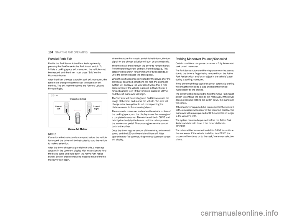
After the driver chooses a parallel park exit maneuver, the
system will then prompt the driver to choose an exit
method. The exit method options are Forward Left and
Forward Right.
Choose Exit Method
NOTE:If an exit method selection is attempted before the vehicle
is stopped, the driver will be instructed to stop the vehicle
to make a selection.
After the driver chooses a parallel exit side, a message
appears in the Uconnect display with instructions to hold
the brake pedal and hold down the Active Park Assist
switch. Both of these conditions must be met before the
maneuver can begin. When the Active Park Assist switch is held down, the turn
signal for the chosen exit side will turn on automatically.
The system will then instruct the driver to remove hands
from the steering wheel and feet from the pedals. This
screen will be shown for a minimum of two seconds, or
until the driver releases the brake pedal.
When the exit sequence is initiated by the driver after the
previously described conditions are met, the Uconnect
system will display a Top View along with either a rear
camera view (if the vehicle is placed in REVERSE) or a
forward camera view (if the vehicle is placed in DRIVE),
and the exit maneuver will begin.
The Top View will have integrated ParkSense arcs in the
image at the front and rear of the vehicle. The arcs will
change color from yellow to red corresponding the
distance zones to the oncoming object.
The automatic maneuver ends when the vehicle is clear of
the parking space, and the display shows the message of
a completed maneuver. The vehicle will be in DRIVE and
held hydraulically by the brakes until the driver presses
the accelerator pedal. The system gives vehicle control
back to the driver.
Once the driver regains control of the vehicle, a chime will
sound and the LED on the switch will turn off. After
approximately five seconds, the previous Uconnect screen
will display.
Parking Maneuver Paused/Canceled
Certain conditions can pause or cancel a Fully Automated
park or exit maneuver.
The ParkSense Automated Parking system can be paused
due to the driver’s finger being removed from the Active
Park Assist switch and/or an object in the vehicle’s path
during a parking maneuver.
If one or more of these scenarios occur, automatic braking
will bring the vehicle to a stop and hold the vehicle
hydraulically by the brakes.
The driver will be instructed to hold the Active Park Assist
switch to continue the park or exit maneuver. If the driver
does not resume holding the switch down, the maneuver
will cancel.
If the maneuver is paused due to an object in the vehicle’s
path, a message will appear in the Uconnect display. The
maneuver will remain paused until the object is no longer
in the vehicle’s path.
The system can also be paused before the Active Park
Assist switch is held down if the driver shifts into
REVERSE.
The driver will be instructed to shift to DRIVE to continue
the maneuver. If the vehicle is shifted into DRIVE, the
process will continue on to the seek/maneuver selection
phase.
23_WS_OM_EN_USC_t.book Page 164
Page 168 of 396
166STARTING AND OPERATING
Once active steering begins, a camera image will appear
in the Uconnect display with instructions that will display
for the duration of the maneuver.
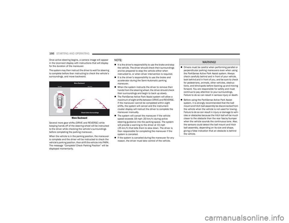
The system may then instruct the driver to wait for steering
to complete before then instructing to check the vehicle’s
surroundings, and move backward.
Move Backward
Several more gear shifts (DRIVE and REVERSE) while
keeping hands off of the steering wheel will be instructed
to the driver while checking the vehicle’s surroundings
before completing the parking maneuver.
When the vehicle is in the parking position, the maneuver
is complete and the driver will be instructed to check the
vehicle's parking position, then shift the vehicle into PARK.
The message “Complete! Check Parking Position” will be
displayed momentarily.
NOTE:
It is the driver's responsibility to use the brake and stop
the vehicle. The driver should check their surroundings
and be prepared to stop the vehicle either when
instructed to, or when driver intervention is required.
It is the driver’s responsibility to use the brake and
accelerator during the Semi-Automatic parking
maneuver.
When the system instructs the driver to remove their
hands from the steering wheel, the driver should check
their surroundings and begin to back up slowly.
The ParkSense Active Park Assist system will allow a
maximum of eight shifts between DRIVE and REVERSE.
If the maneuver cannot be completed within eight
shifts, the system will cancel and the instrument
cluster display will instruct the driver to complete the
maneuver manually.
The system will cancel the maneuver if the vehicle
speed exceeds 18 mph (30 km/h) during active
steering guidance into the parking space. The system
will provide a warning to the driver at 15 mph
(25 km/h) that tells them to slow down. The driver is
then responsible for completing the maneuver if the
system is canceled.
If the system is canceled during the maneuver for any
reason, the driver must take control of the vehicle.WARNING!
Drivers must be careful when performing parallel or
perpendicular parking maneuvers even when using
the ParkSense Active Park Assist system. Always
check carefully behind and in front of your vehicle,
look behind and in front of you, and be sure to check
for pedestrians, animals, other vehicles, obstruc -
tions, and blind spots before backing up and moving
forward. You are responsible for safety and must
continue to pay attention to your surroundings.
Failure to do so can result in serious injury or death.
Before using the ParkSense Active Park Assist
system, it is strongly recommended that the ball
mount and hitch ball assembly be disconnected from
the vehicle when the vehicle is not used for towing.
Failure to do so can result in injury or damage to vehi -
cles or obstacles because the hitch ball will be much
closer to the obstacle than the rear fascia/bumper
when the vehicle sounds the continuous tone. Also,
the sensors could detect the ball mount and hitch
ball assembly, depending on its size and shape,
giving a false indication that an obstacle is behind
the vehicle.
23_WS_OM_EN_USC_t.book Page 166
Page 169 of 396
STARTING AND OPERATING167
Parallel Park Exit
Enable the ParkSense Active Park Assist system by
pressing the ParkSense Active Park Assist switch. To
initiate a parking space exit maneuver, the vehicle must
be stopped, and the driver must press “Exit” on the
Uconnect display.
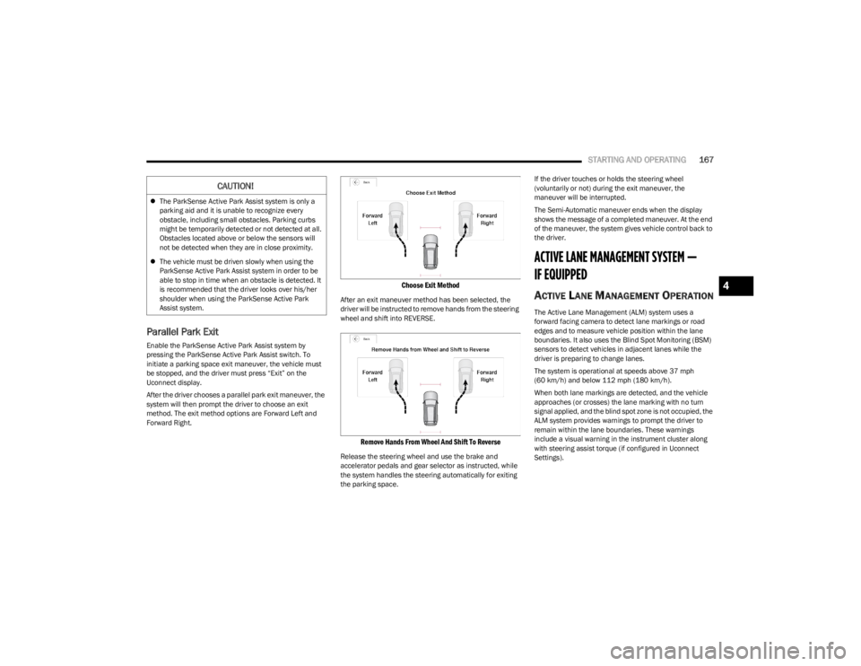
After the driver chooses a parallel park exit maneuver, the
system will then prompt the driver to choose an exit
method. The exit method options are Forward Left and
Forward Right.
Choose Exit Method
After an exit maneuver method has been selected, the
driver will be instructed to remove hands from the steering
wheel and shift into REVERSE.
Remove Hands From Wheel And Shift To Reverse
Release the steering wheel and use the brake and
accelerator pedals and gear selector as instructed, while
the system handles the steering automatically for exiting
the parking space. If the driver touches or holds the steering wheel
(voluntarily or not) during the exit maneuver, the
maneuver will be interrupted.
The Semi-Automatic maneuver ends when the display
shows the message of a completed maneuver. At the end
of the maneuver, the system gives vehicle control back to
the driver.
ACTIVE LANE MANAGEMENT SYSTEM —
IF EQUIPPED
ACTIVE LANE MANAGEMENT OPERATION
The Active Lane Management (ALM) system uses a
forward facing camera to detect lane markings or road
edges and to measure vehicle position within the lane
boundaries. It also uses the Blind Spot Monitoring (BSM)
sensors to detect vehicles in adjacent lanes while the
driver is preparing to change lanes.
The system is operational at speeds above 37 mph
(60 km/h) and below 112 mph (180 km/h).
When both lane markings are detected, and the vehicle
approaches (or crosses) the lane marking with no turn
signal applied, and the blind spot zone is not occupied, the
ALM system provides warnings to prompt the driver to
remain within the lane boundaries. These warnings
include a visual warning in the instrument cluster along
with steering assist torque (if configured in Uconnect
Settings).
CAUTION!
The ParkSense Active Park Assist system is only a
parking aid and it is unable to recognize every
obstacle, including small obstacles. Parking curbs
might be temporarily detected or not detected at all.
Obstacles located above or below the sensors will
not be detected when they are in close proximity.
The vehicle must be driven slowly when using the
ParkSense Active Park Assist system in order to be
able to stop in time when an obstacle is detected. It
is recommended that the driver looks over his/her
shoulder when using the ParkSense Active Park
Assist system.
4
23_WS_OM_EN_USC_t.book Page 167
Page 172 of 396

170STARTING AND OPERATING
NOTE:
The Active Lane Management system operates with
similar behavior for a right lane departure.
If the turn signal is activated, and the vehicle begins to
depart the lane at the same time the Blind Spot Moni -
toring (BSM) system detects another vehicle in the
BSM zones, the system will provide haptic steering
wheel vibration and/or steering assist torque (if
programmed in Uconnect Settings).
CHANGING ACTIVE LANE MANAGEMENT
S
TATUS
Configurable settings for the Active Lane Management
system are available within the Uconnect system
Úpage 197.
Selectable Warning Types:
Vibration Only
Steering Assist Only
Vibration And Steering Assist
Other configurable settings for this system are for the
intensity of the vibration (high/med/low), steering assist
strength (hi/med/low), and the warning zone sensitivity
(early/medium/late).
NOTE:
The system will not apply vibration and/or steering
assist to the steering wheel whenever a safety system
engages (Anti-Lock Brakes, Traction Control System,
Electronic Stability Control, Forward Collision Warning,
etc.).
The Blind Spot Monitoring system will be forced on
when the ALM system is enabled.
The ALM system will be suppressed when the Active
Driving Assist system (if equipped) is engaged.
PARKVIEW REAR BACK UP CAMERA
Your vehicle is equipped with the ParkView Rear Back Up
Camera that allows you to see an on-screen image of the
rear surroundings of your vehicle whenever the gear
selector is put into REVERSE. The image will be displayed
on the Navigation/Multimedia radio display screen along
with a caution note to “Check Entire Surroundings” across
the top of the screen. After five seconds this note will
disappear. The ParkView camera is located on the rear of
the vehicle above the rear license plate.
When the vehicle is shifted out of REVERSE with camera
delay turned off, the rear camera mode is exited and the
previous screen appears.
Manual Activation Of The Back Up Camera
1. Press the Vehicle button located on the bottom of
the Uconnect display and then select the Controls
menu.
2. Press the Back Up Camera icon to turn the Rear View Camera system on.
NOTE:
The Rear View camera can also be turned on manually
through the Apps menu within the Uconnect system.
The ParkView Rear Back Up Camera has program -
mable modes of operation that may be selected
through the Uconnect system
Úpage 197. When the vehicle is shifted out of REVERSE with camera
delay turned off, the rear camera mode is exited and the
previous screen appears. When the vehicle is shifted out
of REVERSE with camera delay turned on, the camera
image will continue to be displayed for up to 10 seconds
unless the following conditions occur: the vehicle speed
exceeds 8 mph (13 km/h), the vehicle is shifted into
PARK, the vehicle’s ignition is placed in the OFF position,
or the touchscreen X button to disable the display of the
Rear View Camera is pressed.
When enabled, active guidelines are overlaid on the image
to illustrate the width of the vehicle and its projected back
up path based on the steering wheel position. A dashed
center line overlay indicates the center of the vehicle to
assist with parking or aligning to a hitch/receiver.
Different colored zones indicate the distance to the rear of
the vehicle.
The following table shows the approximate distances for
each zone:
Zone Distance To The Rear Of The
Vehicle
Red 0 - 1 ft
(0 - 30 cm)
Yellow 1 ft - 6.5 ft
(30 cm - 2 m)
Green 6.5 ft or greater
(2 m or greater)
23_WS_OM_EN_USC_t.book Page 170
Page 187 of 396
STARTING AND OPERATING185
(Continued)
TRAILER AND TONGUE WEIGHT
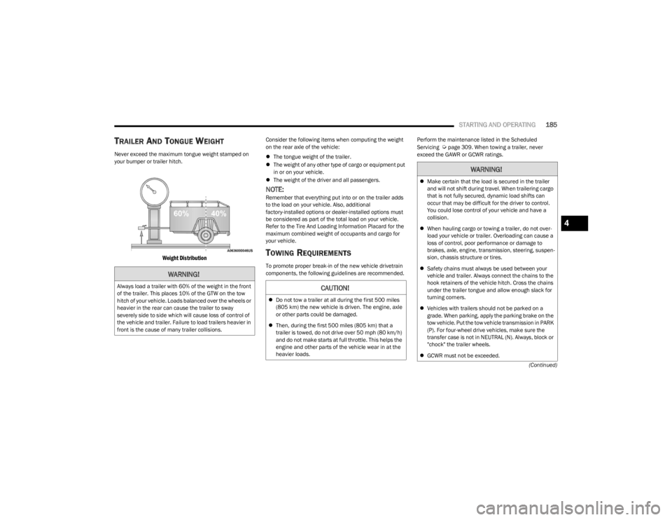
Never exceed the maximum tongue weight stamped on
your bumper or trailer hitch.
Weight Distribution
Consider the following items when computing the weight
on the rear axle of the vehicle:
The tongue weight of the trailer.
The weight of any other type of cargo or equipment put
in or on your vehicle.
The weight of the driver and all passengers.
NOTE:Remember that everything put into or on the trailer adds
to the load on your vehicle. Also, additional
factory-installed options or dealer-installed options must
be considered as part of the total load on your vehicle.
Refer to the Tire And Loading Information Placard for the
maximum combined weight of occupants and cargo for
your vehicle.
TOWING REQUIREMENTS
To promote proper break-in of the new vehicle drivetrain
components, the following guidelines are recommended. Perform the maintenance listed in the Scheduled
Servicing
Úpage 309. When towing a trailer, never
exceed the GAWR or GCWR ratings.
WARNING!
Always load a trailer with 60% of the weight in the front
of the trailer. This places 10% of the GTW on the tow
hitch of your vehicle. Loads balanced over the wheels or
heavier in the rear can cause the trailer to sway
severely side to side which will cause loss of control of
the vehicle and trailer. Failure to load trailers heavier in
front is the cause of many trailer collisions.CAUTION!
Do not tow a trailer at all during the first 500 miles
(805 km) the new vehicle is driven. The engine, axle
or other parts could be damaged.
Then, during the first 500 miles (805 km) that a
trailer is towed, do not drive over 50 mph (80 km/h)
and do not make starts at full throttle. This helps the
engine and other parts of the vehicle wear in at the
heavier loads.
WARNING!
Make certain that the load is secured in the trailer
and will not shift during travel. When trailering cargo
that is not fully secured, dynamic load shifts can
occur that may be difficult for the driver to control.
You could lose control of your vehicle and have a
collision.
When hauling cargo or towing a trailer, do not over -
load your vehicle or trailer. Overloading can cause a
loss of control, poor performance or damage to
brakes, axle, engine, transmission, steering, suspen -
sion, chassis structure or tires.
Safety chains must always be used between your
vehicle and trailer. Always connect the chains to the
hook retainers of the vehicle hitch. Cross the chains
under the trailer tongue and allow enough slack for
turning corners.
Vehicles with trailers should not be parked on a
grade. When parking, apply the parking brake on the
tow vehicle. Put the tow vehicle transmission in PARK
(P). For four-wheel drive vehicles, make sure the
transfer case is not in NEUTRAL (N). Always, block or
"chock" the trailer wheels.
GCWR must not be exceeded.
4
23_WS_OM_EN_USC_t.book Page 185
Page 193 of 396
STARTING AND OPERATING191
(Continued)
5. Properly secure the rear wheels to the dolly, following
the dolly manufacturer’s instructions.
6. Install a suitable clamping device, designed for towing, to secure the front wheels in the straight
position.
RECREATIONAL TOWING —
Q
UADRA-TRAC I (SINGLE-SPEED
T
RANSFER CASE) FOUR-WHEEL DRIVE
M
ODELS
Recreational towing is not allowed. These models do not
have a N (Neutral) position in the transfer case.
NOTE:This vehicle may be towed on a flatbed or vehicle trailer
provided all four wheels are OFF the ground.
RECREATIONAL TOWING —
Q
UADRA–TRAC II/QUADRA–DRIVE II
F
OUR-WHEEL DRIVE MODELS
The transfer case must be shifted into N (Neutral) and the
transmission must be in PARK (P) for recreational towing.
The N (Neutral) selection button is located by the selector
switch.
Shifting Into N (Neutral)
CAUTION!
Towing with the rear wheels on the ground will cause
severe transmission damage. Damage from improper
towing is not covered under the New Vehicle Limited
Warranty.
CAUTION!
Towing this vehicle in violation of the above
requirements can cause severe transmission and/or
transfer case damage. Damage from improper towing is
not covered under the New Vehicle Limited Warranty.
CAUTION!
DO NOT dolly tow any four-wheel drive vehicle.
Towing with only one set of wheels on the ground
(front or rear) will cause severe transmission and/or
transfer case damage. Tow with all four wheels either
ON the ground, or OFF the ground (using a vehicle
trailer).
Tow only in a forward direction. Towing this vehicle
backwards can cause severe damage to the transfer
case.
The transmission must be in PARK for recreational
towing.
Before recreational towing, perform the procedure
outlined under “Shifting into N (Neutral)” to be
certain that the transfer case is fully in N (Neutral).
Otherwise, internal damage will result.
Towing this vehicle in violation of the above require -
ments can cause severe transmission and/or
transfer case damage. Damage from improper
towing is not covered under the New Vehicle Limited
Warranty.
Do not use a bumper-mounted clamp-on tow bar on
your vehicle. The bumper face bar will be damaged.
WARNING!
You or others could be injured or killed if you leave the
vehicle unattended with the transfer case in the N
(Neutral) position without first fully engaging the
parking brake. The transfer case N (Neutral) position
disengages both the front and rear driveshafts from the
powertrain and will allow the vehicle to roll, even if the
transmission is in PARK. The parking brake should
always be applied when the driver is not in the vehicle.
CAUTION!
It is necessary to follow these steps to be certain that
the transfer case is fully in N (Neutral) before
recreational towing to prevent damage to internal parts.
CAUTION!
4
23_WS_OM_EN_USC_t.book Page 191
Page 242 of 396
240SAFETY
REAR SEAT REMINDER ALERT (RSRA)
RSRA alerts you of the possible presence of an object,
passenger, or pet in the rear seats through a visual and
auditory notification. The system will activate
automatically if a rear door was opened within 10 minutes
of the ignition being placed in the ON/RUN position. RSRA
does not directly detect objects, passengers, or pets in the
rear seats. When the previous conditions are met, RSRA
displays the message “Check Rear Seat” on the
instrument cluster display and sounds an auditory alert
upon the driver placing the ignition in the OFF position to
exit the vehicle.
To enable or disable RSRA, see
Úpage 197.
DROWSY DRIVER DETECTION (DDD) —
I
F EQUIPPED
DDD detects when the driver is feeling fatigued and warns
the driver to pull over and take a break.
To Activate/Deactivate
DDD can be activated and deactivated through the
Uconnect system by selecting the following in order:
1. “Safety & Driving Assistance”
2. “Drowsy Driver Detection”
System Intervention
Using feedback obtained from the driver’s steering
patterns, any buttons/switches that are pressed, and from
the front camera, the system implements two operating
logics:
The first operating logic takes the driving style into
account, observing the road and detecting to what
extent the driver can continue driving with few lane
crossing events.
The second operating logic measures the time spent
behind the wheel with the vehicle speed above 40 mph
(60 km/h) and below 100 mph (160 km/h).
If the driving style indicates that the driver is unable to
follow the road trajectory and respect the horizontal lane
markings while within the operating speed range of the
system, a pop up will display on the instrument cluster
display to suggest that the driver should stop for a break.
An audible signal will also sound.
If the driver accepts the suggestion provided by the
system by pushing the “OK” button on the left side of the
steering wheel, the message will disappear from the
display.
If the driver does not acknowledge the warning it will be
displayed for 60 seconds and then disappear.
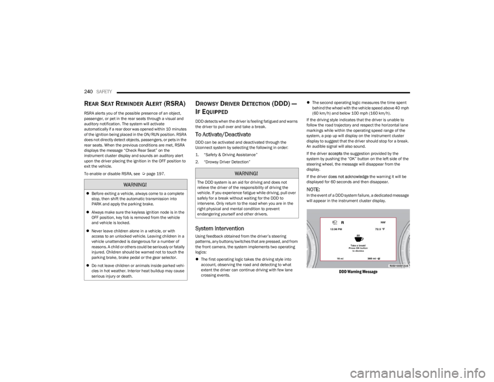
NOTE:In the event of a DDD system failure, a dedicated message
will appear in the instrument cluster display.
DDD Warning Message
WARNING!
Before exiting a vehicle, always come to a complete
stop, then shift the automatic transmission into
PARK and apply the parking brake.
Always make sure the keyless ignition node is in the
OFF position, key fob is removed from the vehicle
and vehicle is locked.
Never leave children alone in a vehicle, or with
access to an unlocked vehicle. Leaving children in a
vehicle unattended is dangerous for a number of
reasons. A child or others could be seriously or fatally
injured. Children should be warned not to touch the
parking brake, brake pedal or the gear selector.
Do not leave children or animals inside parked vehi -
cles in hot weather. Interior heat buildup may cause
serious injury or death.
WARNING!
The DDD system is an aid for driving and does not
relieve the driver of the responsibility of driving the
vehicle. If you experience fatigue while driving, pull over
safely for a break without waiting for the DDD to
intervene. Only return to the road when you are in the
right physical and mental condition to prevent
endangering yourself and other drivers.
23_WS_OM_EN_USC_t.book Page 240
Page 245 of 396
SAFETY243
ESC Activation/Malfunction Indicator Light
And ESC OFF Indicator Light
The ESC Activation/Malfunction Indicator Light
in the instrument cluster will come on when the
ignition is placed in the ON/RUN mode. It
should go out with the engine running. If the
ESC Activation/Malfunction Indicator Light comes on
continuously with the engine running, a malfunction has
been detected in the ESC system. If this light remains on
after several ignition cycles, and the vehicle has been
driven several miles (kilometers) at speeds greater than
30 mph (48 km/h), see an authorized dealer as soon as possible to have the problem diagnosed and corrected. The ESC Activation/Malfunction Indicator Light starts to
flash as soon as the tires lose traction and the ESC system
becomes active. The ESC Activation/Malfunction Indicator
Light also flashes when TCS is active. If the ESC
Activation/Malfunction Indicator Light begins to flash
during acceleration, ease up on the accelerator and apply
as little throttle as possible. Be sure to adapt your speed
and driving to the prevailing road conditions.
The ESC OFF Indicator Light indicates the
customer has elected to have the Electronic
Stability Control (ESC) in a reduced mode.
NOTE:
The ESC Activation/Malfunction Indicator Light and the
ESC OFF Indicator Light come on momentarily each
time the ignition is placed in the ON/RUN mode.
Each time the ignition is placed in the ON/RUN mode,
the ESC system will be on even if it was turned off previ -
ously.
The ESC system will make buzzing or clicking sounds
when it is active. This is normal; the sounds will stop
when ESC becomes inactive following the maneuver
that caused the ESC activation.
Hill Descent Control (HDC) — If Equipped
HDC is intended for low speed off-road driving
while in 4WD Low. HDC maintains vehicle
speed while descending hills during various
driving situations. HDC controls vehicle speed
by actively controlling the brakes. HDC Has Three States:
1. Off (feature is not enabled and will not activate).
2. Enabled (feature is enabled and ready but activation
conditions are not met, or driver is actively overriding
with brake or throttle application).
3. Active (feature is enabled and actively controlling vehicle speed).
Enabling HDC
HDC is enabled by pushing the HDC switch, but the
following conditions must also be met to enable HDC:
The driveline is in 4WD Low.
The vehicle speed is below 5 mph (8 km/h).
The parking brake is released.
The driver door is closed.
Activating HDC
Once HDC is enabled it will activate automatically if driven
down a grade of sufficient magnitude. The set speed for
HDC is selectable by the driver, and can be adjusted by
using the gear shift +/-. The following summarizes the
HDC set speeds:
WARNING!
When in “Partial Off” mode, the TCS functionality of
ESC, except for the limited slip feature described in
the TCS section, has been disabled and the ESC OFF
Indicator Light will be illuminated. When in “Partial
Off” mode, the engine power reduction feature of
TCS is disabled, and the enhanced vehicle stability
offered by the ESC system is reduced.
Trailer Sway Control (TSC) is disabled when the ESC
system is in the “Partial Off” mode.
6
23_WS_OM_EN_USC_t.book Page 243
Page 246 of 396
244SAFETY
HDC Target Set Speeds
P = No set speed. HDC may be enabled but will not
activate.
R = 0.6 mph (1 km/h)
N = 1.2 mph (2 km/h)
D = 0.6 mph (1 km/h)
1st = 0.6 mph (1 km/h)
2nd = 1.2 mph (2 km/h)
3rd = 1.8 mph (3 km/h)
4th = 2.5 mph (4 km/h)
5th = 3.1 mph (5 km/h)
6th = 3.7 mph (6 km/h)
7th = 4.3 mph (7 km/h)
8th = 5.0 mph (8 km/h)
9th = 5.6 mph (9 km/h) – If Equipped
NOTE:During HDC the +/- shifter input is used for HDC target
speed selection, but will not affect the gear chosen by the
transmission. When actively controlling HDC the trans -
mission will shift appropriately for the driver-selected set
speed and corresponding driving conditions.
Driver Override
The driver may override HDC activation with throttle or
brake application at any time.
Deactivating HDC
HDC will be deactivated but remain available if any of the
following conditions occur:
The driver overrides HDC set speed with throttle or
brake application.
The vehicle speed exceeds 20 mph (32 km/h) but
remains below 40 mph (64 km/h).
The vehicle is on a downhill grade of insufficient magni -
tude, is on level ground, or is on an uphill grade.
The vehicle is shifted to PARK.
Disabling HDC
HDC will be deactivated and disabled if any of the
following conditions occur:
The driver pushes the HDC switch.
The driveline is shifted out of 4WD Low.
The parking brake is applied.
The driver door opens.
The vehicle is driven greater than 20 mph (32 km/h)
for greater than 70 seconds.
The vehicle is driven greater than 40 mph (64 km/h)
(HDC exits immediately).
HDC detects excessive brake temperature.
Feedback To The Driver
The instrument cluster has an HDC icon and the HDC
switch has an LED icon, which offers feedback to the
driver about the state HDC is in.
The cluster icon and switch light will illuminate and
remain on solid when HDC is enabled or activated. This
is the normal operating condition for HDC.
The cluster icon and switch light will flash for several
seconds, then extinguish when the driver pushes the
HDC switch but enable conditions are not met.
The cluster icon and switch light will flash for several
seconds, then extinguish when HDC disables due to
excess speed.
The cluster icon and switch light will flash when HDC
deactivates due to overheated brakes. The flashing will
stop and HDC will activate again once the brakes have
cooled sufficiently.
Hill Start Assist (HSA)
HSA is designed to mitigate roll back from a complete stop
while on an incline. If the driver releases the brake while
stopped on an incline, HSA will continue to hold the brake
pressure for a short period. If the driver does not apply the
throttle before this time expires, the system will release
brake pressure and the vehicle will roll down the hill as
normal.
The following conditions must be met in order for HSA to
activate:
The feature must be enabled.
The vehicle must be stopped.
The parking brake must be off.
The driver door must be closed.
The vehicle must be on a sufficient grade.
The gear selection must match vehicle uphill direction
(i.e., vehicle facing uphill is in forward gear; vehicle
backing uphill is in REVERSE (R) gear).
HSA will work in REVERSE gear and all forward gears.
The system will not activate if the transmission is in
PARK (P) or NEUTRAL (N).
WARNING!
HDC is only intended to assist the driver in controlling
vehicle speed when descending hills. The driver must
remain attentive to the driving conditions and is
responsible for maintaining a safe vehicle speed.
23_WS_OM_EN_USC_t.book Page 244
Page 247 of 396
SAFETY245
Disabling And Enabling HSA
This feature can be turned on or turned off. To change the
current setting, proceed as follows:
If disabling HSA using your instrument cluster display,
see
Úpage 99 for further information.
If disabling HSA using Uconnect Settings, see
Úpage 197 for further information.
Towing With HSA
HSA will also provide assistance to mitigate roll back while
towing a trailer.
Rain Brake Support (RBS)
RBS may improve braking performance in wet conditions.
It will periodically apply a small amount of brake pressure
to remove any water buildup on the front brake rotors. It
functions when the windshield wipers are in LO or HI
speed. When RBS is active, there is no notification to the
driver and no driver interaction is required.
Ready Alert Braking (RAB)
RAB may reduce the time required to reach full braking
during emergency braking situations. It anticipates when
an emergency braking situation may occur by monitoring
how fast the throttle is released by the driver. The
Electronic Brake Controller (EBC) will prepare the brake
system for a panic stop.
Selec-Speed Control (SSC) — If Equipped
Selec-Speed Control (SSC) is intended for
off-road driving in 4WD Low only. SSC
maintains vehicle speed by actively controlling
engine torque and brakes.
SSC has three states:
1. Off (feature is not enabled and will not activate)
2. Enabled (feature is enabled and ready but activation conditions are not met, or driver is actively overriding
with brake or throttle application)
3. Active (feature is enabled and actively controlling vehicle speed)
Enabling SSC
SSC is enabled by pushing the SSC switch, but the
following conditions must also be met to enable SSC:
The driveline is in 4WD Low.
The vehicle speed is below 5 mph (8 km/h).
The parking brake is released.
The driver door is closed.
The driver is not applying throttle.
Activating SSC
Once SSC is enabled it will activate automatically once the
following conditions are met:
Driver releases throttle.
Driver releases brake.
Transmission is in any selection other than PARK.
Vehicle speed is below 20 mph (32 km/h).WARNING!
There may be situations where the Hill Start Assist
(HSA) will not activate and slight rolling may occur, such
as on minor hills or with a loaded vehicle, or while
pulling a trailer. HSA is not a substitute for active driving
involvement. It is always the driver’s responsibility to be
attentive to distance to other vehicles, people, and
objects, and most importantly brake operation to
ensure safe operation of the vehicle under all road
conditions. Your complete attention is always required
while driving to maintain safe control of your vehicle.
Failure to follow these warnings can result in a collision
or serious personal injury.
WARNING!
If you use a trailer brake controller with your trailer,
the trailer brakes may be activated and deactivated
with the brake switch. If so, there may not be enough
brake pressure to hold both the vehicle and the
trailer on a hill when the brake pedal is released. In
order to avoid rolling down an incline while resuming
acceleration, manually activate the trailer brake or
apply more vehicle brake pressure prior to releasing
the brake pedal.
HSA is not a parking brake. Always apply the parking
brake fully when exiting your vehicle. Also, be certain
to place the transmission in PARK.
Failure to follow these warnings can result in a colli -
sion or serious personal injury.
6
23_WS_OM_EN_USC_t.book Page 245