seat memory JEEP WAGONEER 2023 Owners Manual
[x] Cancel search | Manufacturer: JEEP, Model Year: 2023, Model line: WAGONEER, Model: JEEP WAGONEER 2023Pages: 396, PDF Size: 15.17 MB
Page 4 of 396

2
INTRODUCTION
KNOW & GO ........................................................................... 9
SYMBOLS KEY .....................................................................10
ROLLOVER WARNING .......................................................10
VEHICLE MODIFICATIONS/ALTERATIONS .......................10
SYMBOLS GLOSSARY ........................................................11
GETTING TO KNOW YOUR VEHICLE
KEYS ....................................................................................16 Key Fob ........................................................................ 16
SENTRY KEY ....................................................................... 20
IGNITION SWITCH ...............................................................20 Keyless Enter ‘n Go™ Ignition .................................... 20
REMOTE START ...................................................................22 How To Use Remote Start .......................................... 22
To Exit Remote Start Mode ....................................... 23
Remote Start Front Defrost Activation —
If Equipped .................................................................. 23
Remote Start Comfort Systems — If Equipped.......... 23
Remote Start Windshield Wiper De-Icer
Activation — If Equipped ............................................. 23
Remote Start Abort Message ..................................... 24
VEHICLE SECURITY SYSTEM — IF EQUIPPED ..................24 To Arm The System ..................................................... 24
To Disarm The System ................................................ 24
Rearming Of The System ............................................ 25
Security System Manual Override.............................. 25
Tamper Alert ................................................................ 25 DELUXE VEHICLE SECURITY SYSTEM —
IF EQUIPPED ........................................................................ 25
To Arm The System ......................................................25
To Disarm The System ................................................ 25
Security System Manual Override ..............................26
DOORS ................................................................................ 26 Manual Door Locks......................................................26
Power Door Locks .......................................................27
Power Side Steps — If Equipped ................................. 27
Keyless Enter ‘n Go™ — Passive Entry ...................... 27
Automatic Unlock Doors On Exit ................................. 30
Automatic Door Locks — If Equipped ......................... 30
Child-Protection Door Lock System — Rear Doors.....30
STEERING WHEEL............................................................... 30 Power Tilt/Telescoping Steering Column ................... 30
Heated Steering Wheel ............................................... 31
DRIVER AND PASSENGER MEMORY SETTINGS —
IF EQUIPPED ........................................................................ 31 Programming The Memory Feature............................ 32
Linking And Unlinking The Key Fob To Memory......... 33
Memory Position Recall............................................... 33
SEATS ................................................................................... 33 Manual Adjustment (Rear Seats) ............................... 33
Power Adjustment (Front Seats) — If Equipped ........ 38
Power Adjustment (Rear Seats) — If Equipped .......... 41
Power Seat Massage — If Equipped ........................... 42
Heated Seats — If Equipped ....................................... 43
Ventilated Seats — If Equipped................................... 44
Head Restraints ........................................................... 44 UCONNECT VOICE RECOGNITION
QUICK TIPS — IF EQUIPPED ............................................. 48
Introducing Voice Recognition .................................... 48
Basic Voice Commands .............................................. 48
Get Started .................................................................. 48
Additional Information ................................................ 49
DRIVER ADJUSTABLE PEDALS ......................................... 49
MIRRORS ............................................................................ 50 Inside Rearview Mirror ................................................ 50
Illuminated Vanity Mirrors .......................................... 50
Outside Mirrors ........................................................... 51
Outside Automatic Dimming Mirror — If Equipped .... 51
Conversation Mirror .................................................... 51
Power Mirrors ............................................................. 52
Automatic Power Folding Mirrors — If Equipped ....... 52
Heated Mirrors ............................................................ 53
Tilt Side Mirrors In Reverse ....................................... 53
UNIVERSAL GARAGE DOOR OPENER
(HOMELINK®) .................................................................... 53 Before You Begin Programming HomeLink® ............ 53
Erasing All The HomeLink® Channels ....................... 54
Identifying Whether You Have A Rolling Code Or
Non-Rolling Code Device............................................. 54
Programming HomeLink® To A Garage
Door Opener ................................................................ 54
Programming HomeLink® To A
Miscellaneous Device ................................................. 55
Reprogramming A Single HomeLink® Button ........... 55
Canadian/Gate Operator Programming .................... 55
Security ........................................................................ 56
Troubleshooting Tips ................................................... 56
23_WS_OM_EN_USC_t.book Page 2
Page 33 of 396
GETTING TO KNOW YOUR VEHICLE31
Use the four-way control to adjust the steering column.
NOTE:For vehicles equipped with Driver Memory Settings, use
the key fob or the memory switch on the driver's door trim
panel to return the tilt/telescopic steering column to
saved positions
Úpage 31.
HEATED STEERING WHEEL
The steering wheel contains a heating element
that helps warm your hands in cold weather.
The heated steering wheel has three
temperature settings. Once the heated
steering wheel has been turned on, it will stay on until the
operator turns it off. The heated steering wheel may not
turn on when it is already warm. The heated steering wheel control button is located on the
left side of the radio screen or within the Uconnect system.
You can gain access to the control button on the top left
side of the screen by tapping the temperature controls,
which will provide a quick drop-down menu containing the
controls, or through the controls screen of the
touchscreen. If your vehicle is not equipped with the
button on the side of the radio, you can also access the
control button through the climate screen.
Press the heated steering wheel button once to turn
the HI setting on.
Press the heated steering wheel button a second time
to turn the MED setting on.
Press the heated steering wheel button a third time to
turn the LO setting on.
Press the heated steering wheel button a fourth time to
turn the heating elements off.NOTE:The engine must be running for the heated steering wheel
to operate.
For information on use with the Remote Start system, see
Úpage 23.
DRIVER AND PASSENGER MEMORY
SETTINGS — IF EQUIPPED
This feature allows the driver, and if equipped, also the
front passenger to save up to two different memory
profiles for easy recall through a memory switch. Each
memory profile saves desired position settings for the
following features:
Driver’s Side
Seat position
Easy entry/exit seat (if equipped)
Side mirrors
Power tilt and telescopic steering column (if equipped)
Power adjustable pedals (if equipped)
A set of desired radio station presets
WARNING!
Do not adjust the steering column while driving.
Adjusting the steering column while driving or driving
with the steering column unlocked, could cause the
driver to lose control of the vehicle. Failure to follow this
warning may result in serious injury or death.
WARNING!
Persons who are unable to feel pain to the skin
because of advanced age, chronic illness, diabetes,
spinal cord injury, medication, alcohol use, exhaus -
tion, or other physical conditions must exercise care
when using the steering wheel heater. It may cause
burns even at low temperatures, especially if used
for long periods.
Do not place anything on the steering wheel that
insulates against heat, such as a blanket or steering
wheel covers of any type and material. This may
cause the steering wheel heater to overheat.
2
23_WS_OM_EN_USC_t.book Page 31
Page 34 of 396
32GETTING TO KNOW YOUR VEHICLE
Passenger’s Side (If Equipped)
Seat position
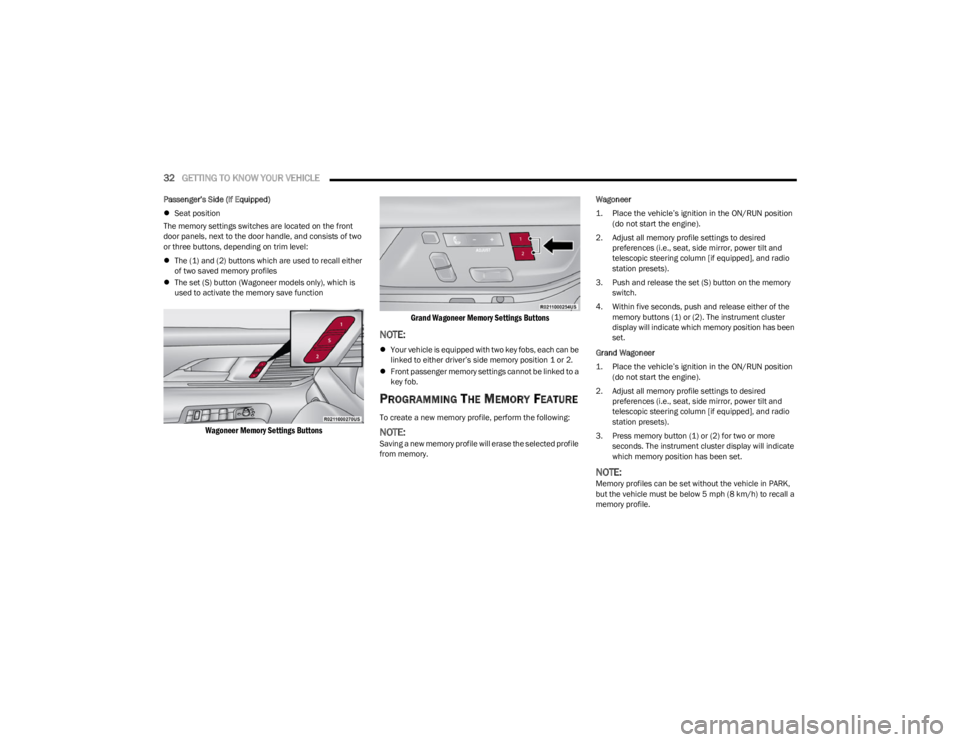
The memory settings switches are located on the front
door panels, next to the door handle, and consists of two
or three buttons, depending on trim level:
The (1) and (2) buttons which are used to recall either
of two saved memory profiles
The set (S) button (Wagoneer models only), which is
used to activate the memory save function
Wagoneer Memory Settings Buttons Grand Wagoneer Memory Settings Buttons
NOTE:
Your vehicle is equipped with two key fobs, each can be
linked to either driver’s side memory position 1 or 2.
Front passenger memory settings cannot be linked to a
key fob.
PROGRAMMING THE MEMORY FEATURE
To create a new memory profile, perform the following:
NOTE:Saving a new memory profile will erase the selected profile
from memory. Wagoneer
1. Place the vehicle’s ignition in the ON/RUN position
(do not start the engine).
2. Adjust all memory profile settings to desired preferences (i.e., seat, side mirror, power tilt and
telescopic steering column [if equipped], and radio
station presets).
3. Push and release the set (S) button on the memory switch.
4. Within five seconds, push and release either of the memory buttons (1) or (2). The instrument cluster
display will indicate which memory position has been
set.
Grand Wagoneer
1. Place the vehicle’s ignition in the ON/RUN position (do not start the engine).
2. Adjust all memory profile settings to desired preferences (i.e., seat, side mirror, power tilt and
telescopic steering column [if equipped], and radio
station presets).
3. Press memory button (1) or (2) for two or more seconds. The instrument cluster display will indicate
which memory position has been set.
NOTE:Memory profiles can be set without the vehicle in PARK,
but the vehicle must be below 5 mph (8 km/h) to recall a
memory profile.
23_WS_OM_EN_USC_t.book Page 32
Page 35 of 396
GETTING TO KNOW YOUR VEHICLE33
LINKING AND UNLINKING THE KEY FOB
T
O MEMORY
Your key fobs can be programmed to recall one of two
saved driver’s side memory profiles.
NOTE:Before programming your key fobs you must select the
“Personal Settings Linked To Key Fob” feature through the
Uconnect Settings
Úpage 197.
To program your key fobs, perform the following:
Wagoneer
1. Place the vehicle’s ignition in the OFF position.
2. Select a desired driver’s side memory profile, 1 or 2.
3. Once the profile has been recalled, push and release the set (S) button on the memory switch.
4. Within five seconds, push and release button (1) or (2) accordingly. “Memory Profile Set” (1 or 2) will
display in the instrument cluster.
5. Push and release the lock button on the key fob within 10 seconds.
NOTE:Your key fobs can be unlinked from your driver’s side
memory settings by pushing the set (S) button, and within
10 seconds, pushing the unlock button on the key fob.
Grand Wagoneer
1. Place the vehicle’s ignition in the OFF position.
2. Recall the desired memory profile (1 or 2). 3. Press the memory button (1) or (2) (according to the
previous selection) for two seconds or more, and
release.
4. Push and hold the lock button on the key fob within 10 seconds.
NOTE:Your key fobs can be unlinked from your driver’s side
memory settings by pushing the memory button (1) or (2)
for two seconds or more and releasing, and then within 10
seconds, pushing and holding the unlock button on the
key fob.
MEMORY POSITION RECALL
NOTE:Memory Recall is available when not in PARK, if the
vehicle speed is below 5 mph (8 km/h).
To recall a memory settings using the memory
switches, push memory button (1) or (2) on the
memory switch.
To recall the driver’s side memory settings using the
key fob, push the unlock button on the key fob linked
to memory position 1 or 2.
A recall can be canceled by pushing any of the memory
buttons during a recall, or by pushing any of the seat
adjustment switches. When a recall is canceled, the seat
and power tilt/telescopic steering column will stop
moving. A delay of one second will occur before another
recall can be selected.
SEATS
Seats are a part of the Occupant Restraint system of the
vehicle.
MANUAL ADJUSTMENT (REAR SEATS)
NOTE:You may experience deformation in the seat cushion from
the seat belt buckles if the seats are left folded for an
extended period of time. This is normal and by simply
unfolding the seats to the open position, over time the
seat cushion will return to its normal shape.
WARNING!
It is dangerous to ride in a cargo area, inside or
outside of a vehicle. In a collision, people riding in
these areas are more likely to be seriously injured or
killed.
Do not allow people to ride in any area of your vehicle
that is not equipped with seats and seat belts. In a
collision, people riding in these areas are more likely
to be seriously injured or killed.
Be sure everyone in your vehicle is in a seat and
using a seat belt properly.
WARNING!
Do not pile luggage or cargo higher than the top of the
seatback. This could impair visibility or become a
dangerous projectile in a sudden stop or collision.
2
23_WS_OM_EN_USC_t.book Page 33
Page 43 of 396
GETTING TO KNOW YOUR VEHICLE41
(Continued)
When enabled in Uconnect Settings, Easy Entry and Easy
Exit positions are stored in each memory setting profile
Úpage 31.
NOTE:The Easy Entry/Exit feature is not enabled when the
vehicle is delivered from the factory. The Easy Entry/Exit
feature is enabled or disabled through the programmable
features in the Uconnect system
Úpage 197.
POWER ADJUSTMENT (REAR SEATS) —
I
F EQUIPPED
Third Row Power Recline — If Equipped
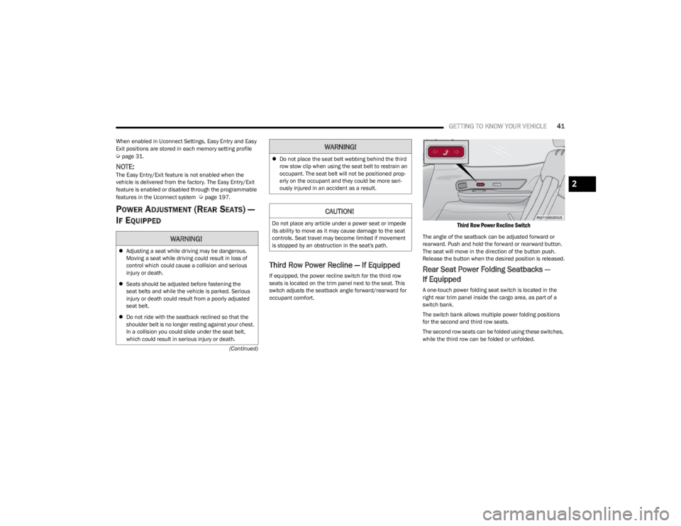
If equipped, the power recline switch for the third row
seats is located on the trim panel next to the seat. This
switch adjusts the seatback angle forward/rearward for
occupant comfort.
Third Row Power Recline Switch
The angle of the seatback can be adjusted forward or
rearward. Push and hold the forward or rearward button.
The seat will move in the direction of the button push.
Release the button when the desired position is released.
Rear Seat Power Folding Seatbacks —
If Equipped
A one-touch power folding seat switch is located in the
right rear trim panel inside the cargo area, as part of a
switch bank.
The switch bank allows multiple power folding positions
for the second and third row seats.
The second row seats can be folded using these switches,
while the third row can be folded or unfolded.
WARNING!
Adjusting a seat while driving may be dangerous.
Moving a seat while driving could result in loss of
control which could cause a collision and serious
injury or death.
Seats should be adjusted before fastening the
seat belts and while the vehicle is parked. Serious
injury or death could result from a poorly adjusted
seat belt.
Do not ride with the seatback reclined so that the
shoulder belt is no longer resting against your chest.
In a collision you could slide under the seat belt,
which could result in serious injury or death.
Do not place the seat belt webbing behind the third
row stow clip when using the seat belt to restrain an
occupant. The seat belt will not be positioned prop -
erly on the occupant and they could be more seri -
ously injured in an accident as a result.
CAUTION!
Do not place any article under a power seat or impede
its ability to move as it may cause damage to the seat
controls. Seat travel may become limited if movement
is stopped by an obstruction in the seat's path.
WARNING!
2
23_WS_OM_EN_USC_t.book Page 41
Page 45 of 396
GETTING TO KNOW YOUR VEHICLE43
(Continued)
The massage type and intensity level status will be
synchronized between the main Uconnect display and the
Front Comfort and Convenience Display.
The selected settings will save in the system’s memory
when turned off, and will resume the next time the system
is turned on.
NOTE:
For vehicles equipped with a selectable back/cushion
feature for massage seats, the massage feature can
be deselected for either the seatback or seat cushion.
If both options are deselected, massage will turn off.
The engine must be running for the power seatback
massage to operate.
The massage feature will turn off after 20 minutes of
use. However, if the massage type or intensity level is
changed, the timer then resets.
HEATED SEATS — IF EQUIPPED
Front Heated Seats
The front heated seats control buttons are
located on the sides of the radio or within the
Uconnect system. You can access the controls
through the Climate screen.
Press the heated seat button once to turn the HI setting
on.
Press the heated seat button a second time to turn the
MED setting on.
Press the heated seat button a third time to turn the
LO setting on.
Press the heated seat button a fourth time to turn the
heating elements off.
The heating elements can be turned on in the seatback
only, seat cushion only, or both. Press the seat image on
the touchscreen or push the seat zone button on the side
of the radio to cycle through these seat zones. An LED will
illuminate next to the selected zone(s). If equipped with
touchscreen buttons, the selected zones will be
highlighted on the seat image.
NOTE:
Once a heat setting is selected, heat will be felt within
two to five minutes.
The engine must be running for the heated seats to
operate.
The level of heat selected will stay on until the operator
changes it.
For information on use with the Remote Start system, see
Úpage 23.
Rear Heated Seats — If Equipped
The two second row outboard seats may be
equipped with heated seats. There are two
heated seat switches that allow the rear
passengers to operate the seats
independently. The heated seat switches for each heater
are located on the rear of the center console.
If equipped with a Rear Comfort And Convenience Display,
heated seat settings can be selected within the display
Úpage 69.
You can choose from HI, MED, LO, or OFF heat settings.
Indicator lights in each switch illuminate indicating the
level of heat in use.
Push the heated seat switch once to turn the HI setting
on.
Push the heated seat switch a second time to turn the
MED setting on.
Push the heated seat switch a third time to turn the
LO setting on.
Push the heated seat switch a fourth time to turn the
heating elements off.WARNING!
Persons who are unable to feel pain to the skin
because of advanced age, chronic illness, diabetes,
spinal cord injury, medication, alcohol use, exhaus -
tion or other physical condition must exercise care
when using the seat heater. It may cause burns even
at low temperatures, especially if used for long
periods of time.
Do not place anything on the seat or seatback that
insulates against heat, such as a blanket or cushion.
This may cause the seat heater to overheat. Sitting in
a seat that has been overheated could cause serious
burns due to the increased surface temperature of
the seat.
WARNING!
2
23_WS_OM_EN_USC_t.book Page 43
Page 51 of 396
GETTING TO KNOW YOUR VEHICLE49
Uconnect Voice Command Buttons
ADDITIONAL INFORMATION
© 2022 FCA US LLC. All rights reserved. Mopar and
Uconnect are registered trademarks and Mopar Owner
Connect is a trademark of FCA US LLC. SiriusXM® and all
related marks and logos are trademarks of SiriusXM®
Radio Inc.
Úpage 382.
For Uconnect system support, call 1-877-855-8400
(24 hours a day 7 days a week) or visit DriveUconnect.com
(US) or DriveUconnect.ca (Canada).
DRIVER ADJUSTABLE PEDALS
The adjustable pedals system is designed to allow a
greater range of driver comfort for steering wheel tilt and
seat position. This feature allows the brake and
accelerator pedals to move toward or away from the driver
to provide improved position with the steering wheel.
The adjustable pedal switch is located on the instrument
panel, next to the headlight switch.
Adjustable Pedals Switch
The pedals can be adjusted with the ignition in the OFF
position.
The pedals cannot be adjusted when the vehicle is in
REVERSE or when the Cruise Control system or Adap -
tive Cruise Control system is on. If there is an attempt
to adjust the pedals when the system is locked out, the
following messages will appear:
Adjustable Pedal Disabled — Cruise Control
Engaged
Adjustable Pedal Disabled — Vehicle In Reverse
NOTE:
Always adjust the pedals to a position that allows full
movement of the pedal.
Further small adjustments may be necessary to find
the best possible seat/pedal position.
For vehicles equipped with Driver Memory Settings
Úpage 31, you can use your key fob or the memory
switch on the driver’s door trim panel to return the
adjustable pedals to saved positions.
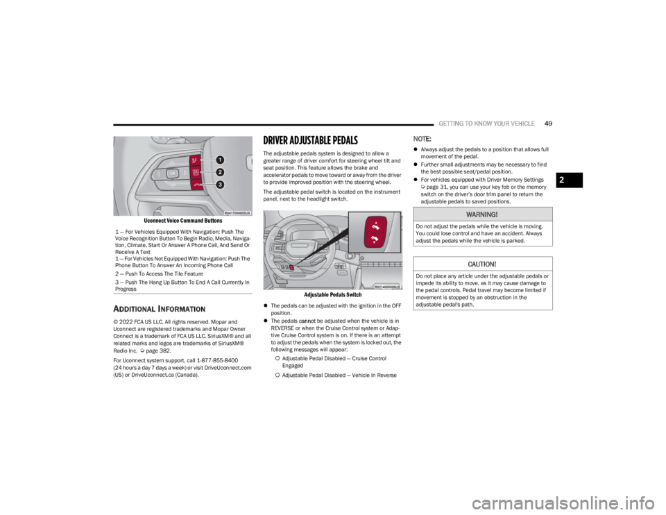
1 — For Vehicles Equipped With Navigation: Push The
Voice Recognition Button To Begin Radio, Media, Naviga -
tion, Climate, Start Or Answer A Phone Call, And Send Or
Receive A Text
1 — For Vehicles Not Equipped With Navigation: Push The
Phone Button To Answer An Incoming Phone Call
2 — Push To Access The Tile Feature
3 — Push The Hang Up Button To End A Call Currently In
Progress
WARNING!
Do not adjust the pedals while the vehicle is moving.
You could lose control and have an accident. Always
adjust the pedals while the vehicle is parked.
CAUTION!
Do not place any article under the adjustable pedals or
impede its ability to move, as it may cause damage to
the pedal controls. Pedal travel may become limited if
movement is stopped by an obstruction in the
adjustable pedal's path.
2
23_WS_OM_EN_USC_t.book Page 49
Page 144 of 396
142STARTING AND OPERATING
The Electronic Stability Control/Traction Control
System (ESC/TCS) activates
The vehicle parking brake is applied
The Trailer Sway Control (TSC) activates
The driver switches ESC to Full Off mode
The braking temperature exceeds normal range (over -
heated)
The following conditions will only cancel the ACC system:
Driver seat belt is unbuckled at low speeds
Driver door is opened at low speeds
To Turn Off
The system will turn off and erase the set speed in
memory if:
The Adaptive Cruise Control (ACC) on/off button is
pushed
The Fixed Speed Cruise Control (if equipped) on/off
button is pushed
The ignition is placed in the OFF position
4WD Low is engaged
To Resume
If there is a set speed in memory, push the RES (resume)
button and remove your foot from the accelerator pedal.
The instrument cluster display will show the last set
speed.
Resume can be used at any speed above 20 mph
(32 km/h) when only Fixed Speed Cruise Control is
being used.
Resume can be used at any speed above 0 mph (0 km/h)
when ACC is active.
NOTE:
While in ACC mode, when the vehicle comes to a
complete stop longer than two seconds, the driver will
either have to push the RES (resume) button or press
the accelerator pedal to reengage the ACC system.
ACC cannot be resumed if there is a stationary vehicle
in front of your vehicle in close proximity.
To Vary The Speed Setting
To Increase Or Decrease The Set Speed
After setting a speed, you can increase the set speed by
pushing the SET (+) button, or decrease speed by pushing
the SET (-) button.
U.S. Speed (mph)
Pushing the SET (+), or SET (-) button once will result in
a 1 mph speed adjustment. Each subsequent tap of
the button results in an adjustment of 1 mph.
If the button is continually pushed, the set speed will
continue to adjust in 5 mph increments until the button
is released. The new set speed is reflected in the instru -
ment cluster display. Metric Speed (km/h)
Pushing the SET (+), or SET (-) button once will result in
a 1 km/h speed adjustment. Each subsequent tap of
the button results in an adjustment of 1 km/h.
If the button is continually pushed, the set speed will
continue to adjust in 10 km/h increments until the
button is released. The new set speed is reflected in
the instrument cluster display.
NOTE:When you override and push the SET (+) button or SET (-)
button, the new set speed will be the current speed of the
vehicle.
When ACC Is Active
When you use the SET (-) button to decelerate, if the
engine’s braking power does not slow the vehicle suffi -
ciently to reach the set speed, the brake system will
automatically slow the vehicle.
The ACC system decelerates the vehicle to a full stop
when following the vehicle in front. If your vehicle
follows the vehicle in front to a standstill, after two
seconds the driver will either have to push the RES
(resume) button, or apply the accelerator pedal to reen -
gage the ACC to the existing set speed.
The ACC system maintains set speed when driving
uphill and downhill. However, a slight speed change on
moderate hills is normal. In addition, downshifting may
occur while climbing uphill or descending downhill. This
is normal operation and necessary to maintain set
speed. When driving uphill and downhill, the ACC
system will cancel if the braking temperature exceeds
normal range (overheated).
WARNING!
The Resume function should only be used if traffic and
road conditions permit. Resuming a set speed that is
too high or too low for prevailing traffic and road
conditions could cause the vehicle to accelerate or
decelerate too sharply for safe operation. Failure to
follow these warnings can result in a collision and death
or serious personal injury.
23_WS_OM_EN_USC_t.book Page 142
Page 347 of 396

SERVICING AND MAINTENANCE345
F21B –10 Amp RedSunroof - Dual Pane 2nd & 3rd Row Seat SW-Illumination
F22 ––Spare
F23 –10 Amp RedRear Seat Entertainment (Driver / Passenger)
F24 ––Spare
F25 30 Amp Pink –Mod Door MUX Passenger
F26 ––Spare
F27 ––Spare
F28 30 Amp Pink –MOD Memory / Power Seat (Passenger Frt)
F29A –10 Amp RedAnimation Lighting RR-RT
F29B –10 Amp RedAnimation Lighting RR-LT
F30 30 Amp Pink –MOD Memory / Power Seat (Driver Frt)
F31 ––Spare
F32 ––Spare
F33 ––Spare
F34 30 Amp Pink –MOD Door MUX Driver
F35 25 Amp Clear –Integrated Trailer Tow Module #2
F36A –10 Amp RedIntelligent Event Base Lighting Module
F36B ––Spare
F37 25 Amp Clear –Integrated Trailer Tow Module #1
F38 ––Spare
F39 ––Spare
F40 –30 Amp Green Mod Audio Amplifier #1A
CavityCartridge Fuse Micro Fuse Description
* If Equipped
8
23_WS_OM_EN_USC_t.book Page 345
Page 389 of 396

387
Fog .............................................................................. 60
Hazard Warning Flasher ......................................... 290
Headlights On With Wipers .......................................59
High Beam/Low Beam Select ...................................58
Hill Descent Control Indicator ................................ 243
Illuminated Entry........................................................62
Interior ........................................................................60
Lights On Reminder ...................................................59
Malfunction Indicator (Check Engine) ................... 112
Multicolor Ambient ....................................................62
Park .................................................................. 59
, 116
Passing ....................................................................... 58
Reading ...................................................................... 61
Seat Belt Reminder ................................................ 111
Security Alarm ......................................................... 111 Service ..................................................................... 349
Traction Control ...................................................... 243
Turn Signals ..................................... 57
, 60, 116, 289
Vanity Mirror............................................................... 50
Warning Instrument Cluster Descriptions ............. 110
Load Shed Battery Saver Mode .................................. 107
Load Shed Battery Saver On ....................................... 107
Load Shed Electrical Load Reduction......................... 107
Load Shed Intelligent Battery Sensor ......................... 107
Loading Vehicle ............................................................ 178 Tires ......................................................................... 354
Locks Child Protection .........................................................30
Manual ....................................................................... 26
Power Door .................................................................27
Lubrication, Body ......................................................... 323
Lug Nuts/Bolts ............................................................. 371
MMaintenance ................................................................... 85 Maintenance Free Battery ...........................................318
Maintenance Schedule ................................................ 309
Malfunction Indicator Light (Check Engine) ...... 112
, 118
Manual Park Release............................................................303Service .....................................................................381
McIntosh ....................................................................... 226
Media Hub....................................................................... 76
Memory Feature (Memory Seats) .................................. 31
Memory Seat ................................................................... 31 Memory Seats And Radio............................................... 31
Methanol ....................................................................... 373
Mirrors ............................................................................. 50 Conversation .............................................................. 51
Electric Remote ......................................................... 52
Exterior Folding.......................................................... 51
Heated........................................................................ 53
Outside ....................................................................... 51
Rearview ...........................................................50
, 290
Tilt In Reverse ............................................................ 53
Vanity.......................................................................... 50
Modifications/Alterations Vehicle........................................................................ 10
Monitor, Tire Pressure System..................................... 252
Mopar Parts .................................................................. 381
MP3 Control .................................................................... 76 Multi-Function Control Lever .......................................... 57
NNew Vehicle Break-In Period ....................................... 122
Night Vision Camera..................................................... 172
OOccupant Restraints .................................................... 256
Octane Rating, Gasoline (Fuel) .................................... 372
Off-Road Pages ............................................................. 236
Oil Change Indicator ..................................................... 101 Reset........................................................................ 101
Oil Filter, Change .......................................................... 319
Oil Filter, Selection ....................................................... 319
Oil Pressure Light ......................................................... 111
Oil, Engine ..................................................................... 319 Capacity ................................................................... 375
Checking .........................................................316
, 317
Dipstick ...........................................................316, 317
Disposal ................................................................... 319
Filter ......................................................................... 319
Filter Disposal.......................................................... 319
Identification Logo .................................................. 319
Materials Added To ................................................. 319 Pressure Warning Light .......................................... 111Recommendation...........................................319
, 375
Synthetic .................................................................. 319
Viscosity ................................................................... 375
Onboard Diagnostic System ........................................ 117
Operating Precautions ................................................. 117
Operator Manual Owner's Manual ...................................................... 381
Outside Rearview Mirrors .............................................. 51
11
23_WS_OM_EN_USC_t.book Page 387