brake sensor JEEP WRANGLER 1994 User Guide
[x] Cancel search | Manufacturer: JEEP, Model Year: 1994, Model line: WRANGLER, Model: JEEP WRANGLER 1994Pages: 1770, PDF Size: 75.27 MB
Page 943 of 1770
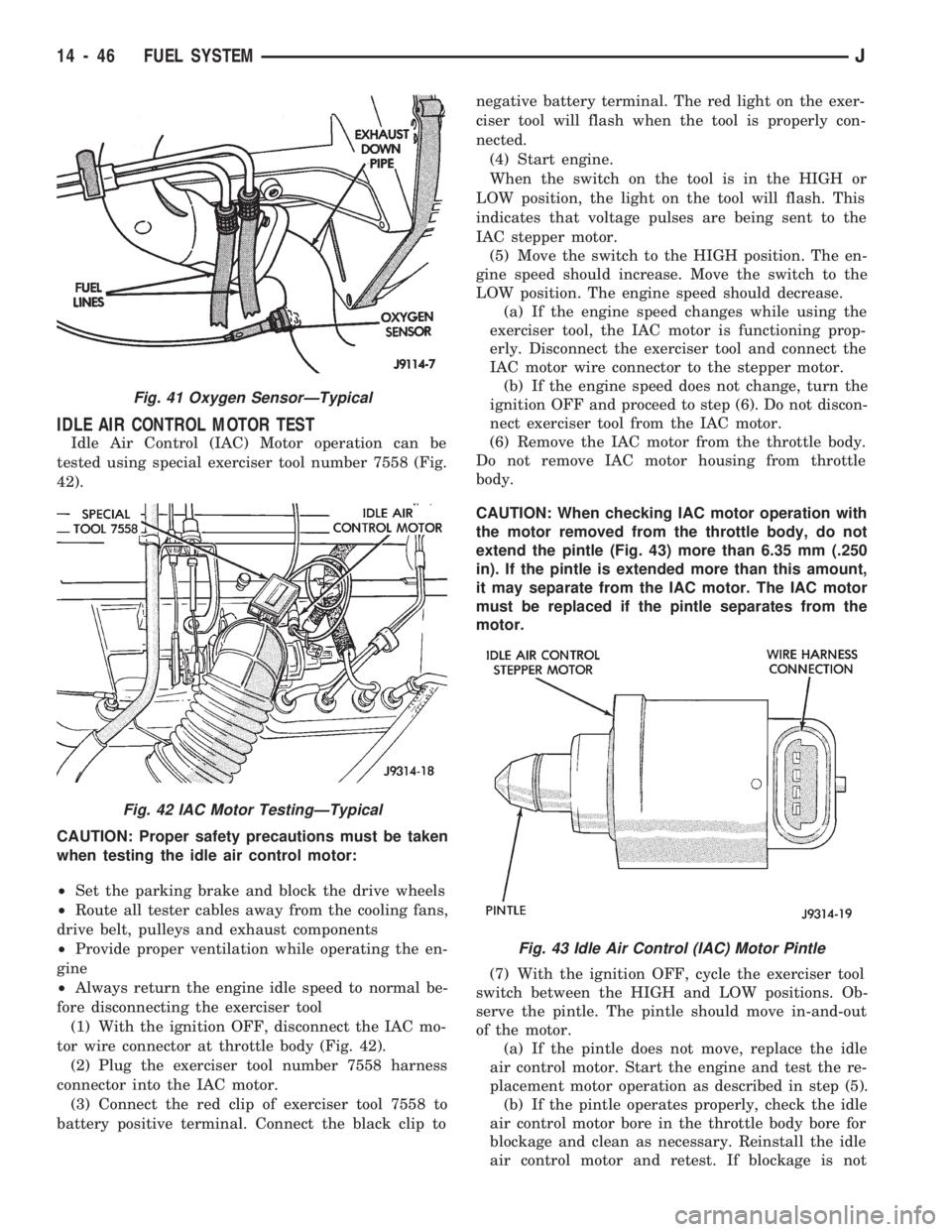
IDLE AIR CONTROL MOTOR TEST
Idle Air Control (IAC) Motor operation can be
tested using special exerciser tool number 7558 (Fig.
42).
CAUTION: Proper safety precautions must be taken
when testing the idle air control motor:
²Set the parking brake and block the drive wheels
²Route all tester cables away from the cooling fans,
drive belt, pulleys and exhaust components
²Provide proper ventilation while operating the en-
gine
²Always return the engine idle speed to normal be-
fore disconnecting the exerciser tool
(1) With the ignition OFF, disconnect the IAC mo-
tor wire connector at throttle body (Fig. 42).
(2) Plug the exerciser tool number 7558 harness
connector into the IAC motor.
(3) Connect the red clip of exerciser tool 7558 to
battery positive terminal. Connect the black clip tonegative battery terminal. The red light on the exer-
ciser tool will flash when the tool is properly con-
nected.
(4) Start engine.
When the switch on the tool is in the HIGH or
LOW position, the light on the tool will flash. This
indicates that voltage pulses are being sent to the
IAC stepper motor.
(5) Move the switch to the HIGH position. The en-
gine speed should increase. Move the switch to the
LOW position. The engine speed should decrease.
(a) If the engine speed changes while using the
exerciser tool, the IAC motor is functioning prop-
erly. Disconnect the exerciser tool and connect the
IAC motor wire connector to the stepper motor.
(b) If the engine speed does not change, turn the
ignition OFF and proceed to step (6). Do not discon-
nect exerciser tool from the IAC motor.
(6) Remove the IAC motor from the throttle body.
Do not remove IAC motor housing from throttle
body.
CAUTION: When checking IAC motor operation with
the motor removed from the throttle body, do not
extend the pintle (Fig. 43) more than 6.35 mm (.250
in). If the pintle is extended more than this amount,
it may separate from the IAC motor. The IAC motor
must be replaced if the pintle separates from the
motor.
(7) With the ignition OFF, cycle the exerciser tool
switch between the HIGH and LOW positions. Ob-
serve the pintle. The pintle should move in-and-out
of the motor.
(a) If the pintle does not move, replace the idle
air control motor. Start the engine and test the re-
placement motor operation as described in step (5).
(b) If the pintle operates properly, check the idle
air control motor bore in the throttle body bore for
blockage and clean as necessary. Reinstall the idle
air control motor and retest. If blockage is not
Fig. 41 Oxygen SensorÐTypical
Fig. 42 IAC Motor TestingÐTypical
Fig. 43 Idle Air Control (IAC) Motor Pintle
14 - 46 FUEL SYSTEMJ
Page 951 of 1770
MULTI-PORT FUEL INJECTION (MFI)ÐCOMPONENT REMOVAL/INSTALLATION
INDEX
page page
Accelerator Pedal and Throttle Cable......... 54
Air Cleaner Housing...................... 54
Air Conditioning (A/C) Clutch Relay........... 54
Air Filter............................... 54
Automatic Shut Down (ASD) Relay........... 54
Brake Switch............................ 54
Camshaft Position Sensor.................. 54
Crankshaft Position Sensor................. 55
Engine Coolant Temperature Sensor.......... 55
Fuel Filter.............................. 55
Fuel Injector............................ 55
Fuel Pump Module....................... 56
Fuel Pump Relay........................ 56
Fuel Rail Assembly....................... 56
Fuel System Pressure Release Procedure...... 56
Fuel Tank Pressure Relief/Rollover Valve...... 56
Fuel Tanks............................. 56Fuel Tubes/Lines/Hoses and Clamps.......... 56
Idle Air Control (IAC) Motor................. 56
Ignition Coil............................. 57
Intake Air Temperature Sensor.............. 54
Intake Manifold.......................... 57
Manifold Absolute Pressure (MAP) Sensor..... 57
Oxygen (O2S) Sensor..................... 57
Park Neutral Switch....................... 58
Power Steering Pressure SwitchÐ2.5L
Engine Only........................... 58
Powertrain Control Module (PCM)............ 58
Quick-Connect Fittings..................... 59
Throttle Body............................ 59
Throttle Position Sensor (TPS).............. 59
Torque Converter Clutch Relay.............. 60
Vehicle Speed Sensor..................... 60
ACCELERATOR PEDAL AND THROTTLE CABLE
Refer to the Accelerator Pedal and Throttle Cable
section of this group for removal/installation proce-
dures.
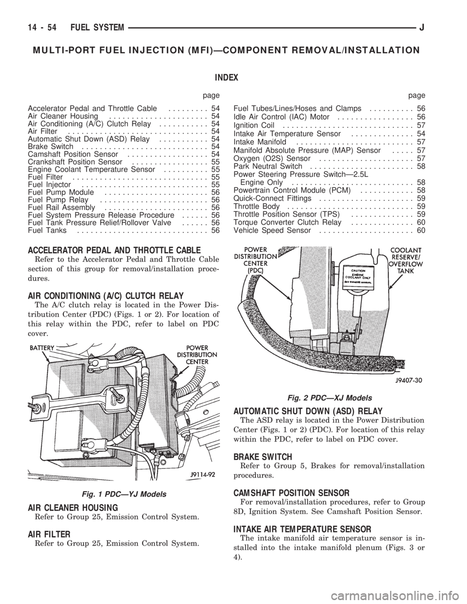
AIR CONDITIONING (A/C) CLUTCH RELAY
The A/C clutch relay is located in the Power Dis-
tribution Center (PDC) (Figs. 1 or 2). For location of
this relay within the PDC, refer to label on PDC
cover.
AIR CLEANER HOUSING
Refer to Group 25, Emission Control System.
AIR FILTER
Refer to Group 25, Emission Control System.
AUTOMATIC SHUT DOWN (ASD) RELAY
The ASD relay is located in the Power Distribution
Center (Figs. 1 or 2) (PDC). For location of this relay
within the PDC, refer to label on PDC cover.
BRAKE SWITCH
Refer to Group 5, Brakes for removal/installation
procedures.
CAMSHAFT POSITION SENSOR
For removal/installation procedures, refer to Group
8D, Ignition System. See Camshaft Position Sensor.
INTAKE AIR TEMPERATURE SENSOR
The intake manifold air temperature sensor is in-
stalled into the intake manifold plenum (Figs. 3 or
4).
Fig. 1 PDCÐYJ Models
Fig. 2 PDCÐXJ Models
14 - 54 FUEL SYSTEMJ
Page 1000 of 1770
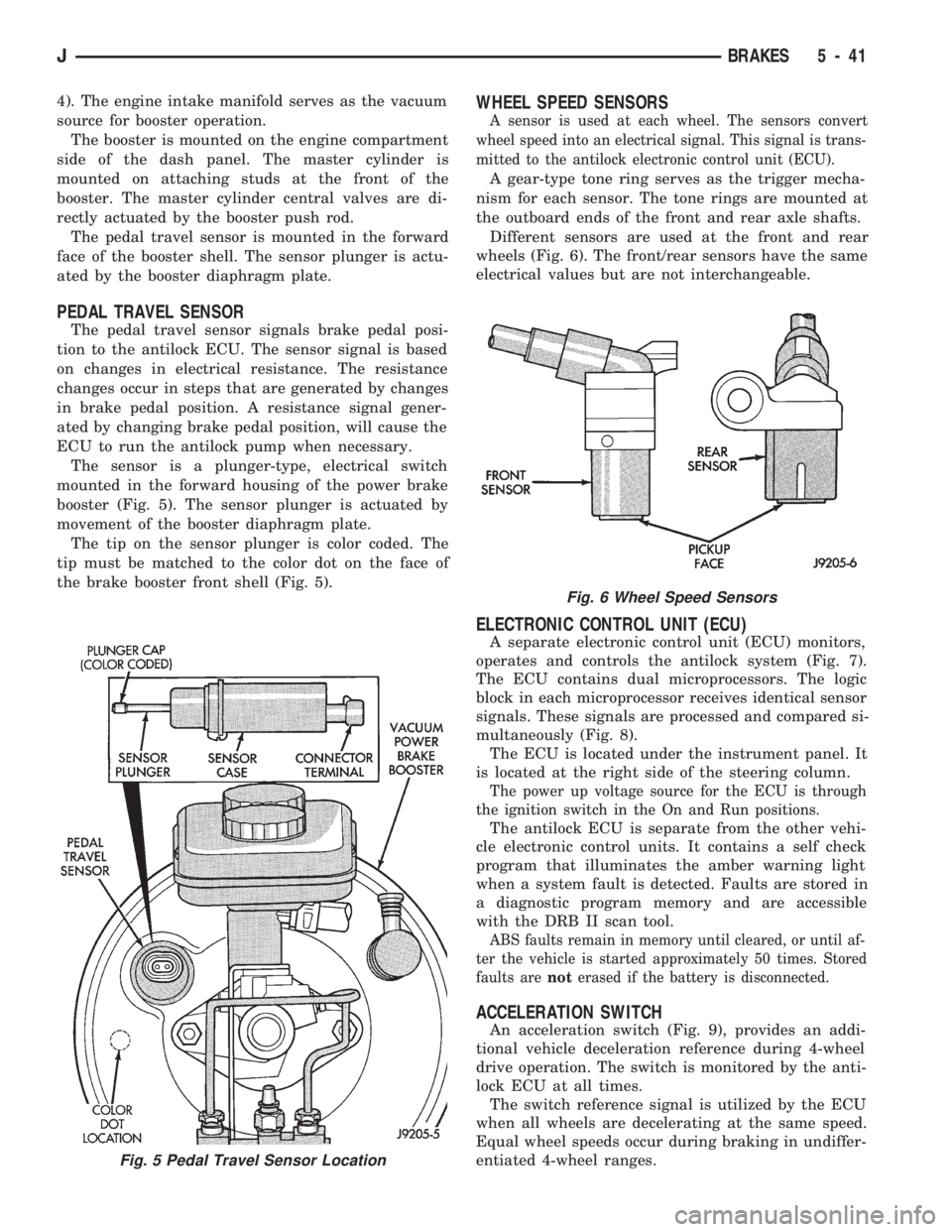
Fig. 6 Wheel Speed Sensors
JBRAKES 5 - 41
Page 1004 of 1770
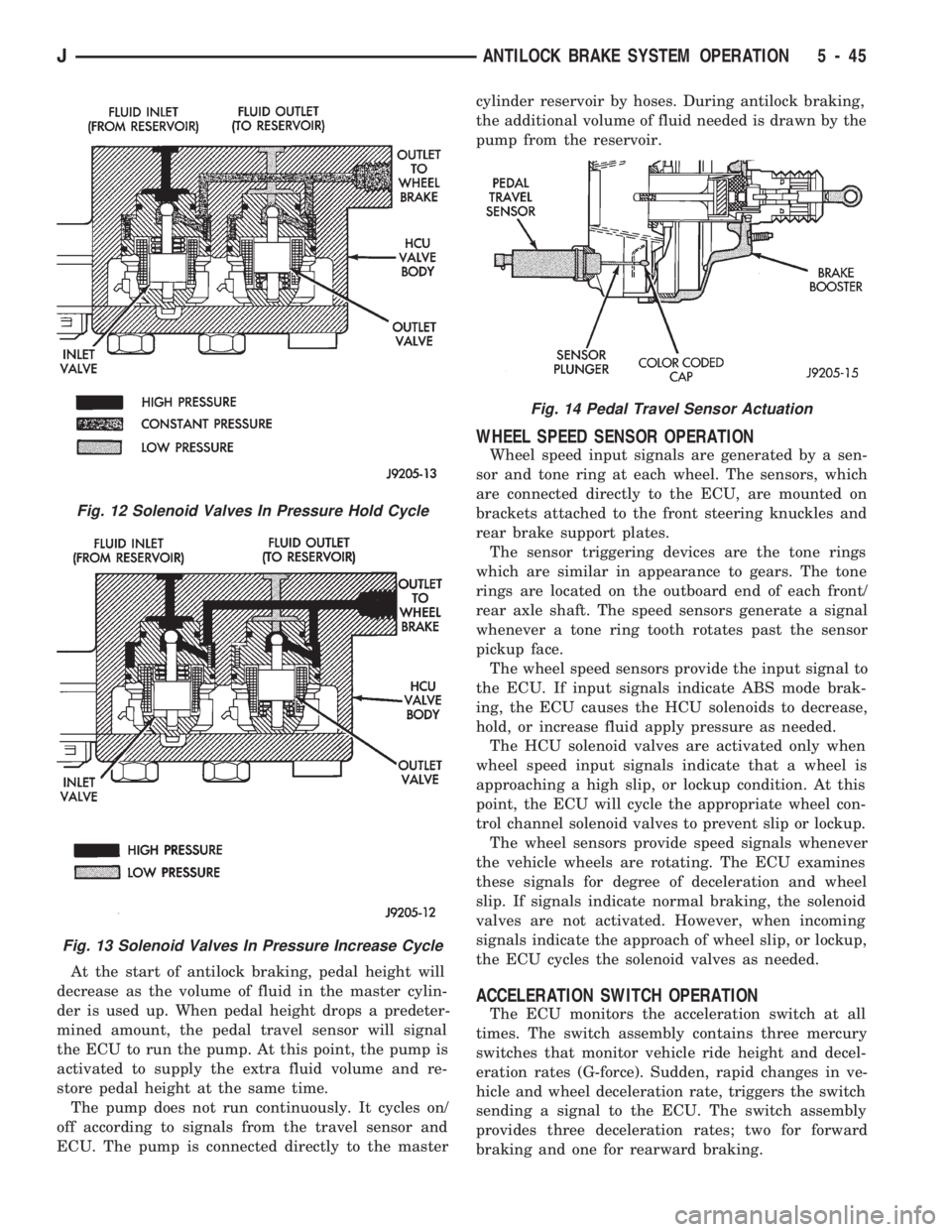
Fig. 13 Solenoid Valves In Pressure Increase Cycle
Fig. 14 Pedal Travel Sensor Actuation
JANTILOCK BRAKE SYSTEM OPERATION 5 - 45
Page 1378 of 1770
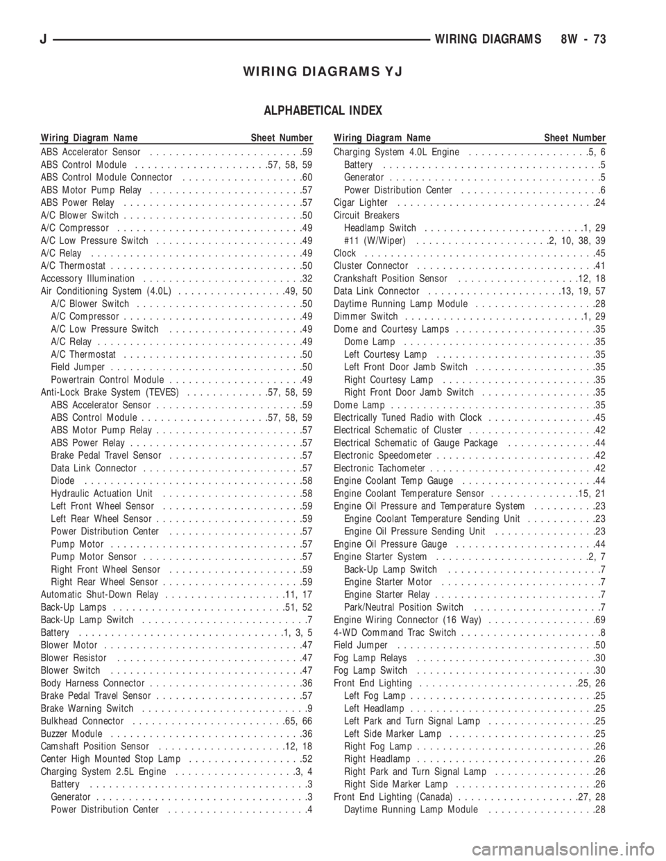
Wiring Diagram Name Sheet Number
ABS Accelerator Sensor........................59
ABS Control Module.....................57, 58, 59
ABS Control Module Connector...................60
ABS Motor Pump Relay........................57
ABS Power Relay............................57
A/C Blower Switch............................50
A/C Compressor.............................49
A/C Low Pressure Switch.......................49
A/C Relay.................................49
A/C Thermostat..............................50
Accessory Illumination.........................32
Air Conditioning System (4.0L).................49, 50
A/C Blower Switch..........................50
A/C Compressor............................49
A/C Low Pressure Switch.....................49
A/C Relay................................49
A/C Thermostat............................50
Field Jumper..............................50
Powertrain Control Module.....................49
Anti-Lock Brake System (TEVES).............57, 58, 59
ABS Accelerator Sensor.......................59
ABS Control Module....................57, 58, 59
ABS Motor Pump Relay.......................57
ABS Power Relay...........................57
Brake Pedal Travel Sensor.....................57
Data Link Connector.........................57
Diode..................................58
Hydraulic Actuation Unit......................58
Left Front Wheel Sensor......................59
Left Rear Wheel Sensor.......................59
Power Distribution Center.....................57
Pump Motor..............................57
Pump Motor Sensor.........................57
Right Front Wheel Sensor.....................59
Right Rear Wheel Sensor......................59
Automatic Shut-Down Relay...................11, 17
Back-Up Lamps...........................51, 52
Back-Up Lamp Switch..........................7
Battery................................1,3,5
Blower Motor...............................47
Blower Resistor.............................47
Blower Switch..............................47
Body Harness Connector........................36
Brake Pedal Travel Sensor.......................57
Brake Warning Switch..........................9
Bulkhead Connector........................65, 66
Buzzer Module..............................36
Camshaft Position Sensor....................12, 18
Center High Mounted Stop Lamp..................52
Charging System 2.5L Engine...................3,4
Battery..................................3
Generator.................................3
Power Distribution Center......................4
Page 1454 of 1770
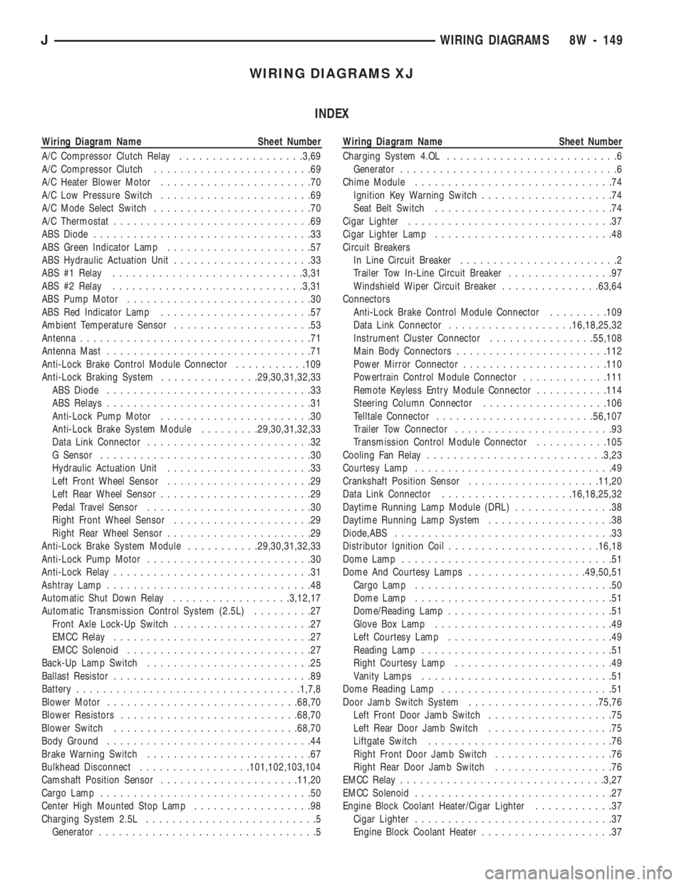
Wiring Diagram Name Sheet Number
A/C Compressor Clutch Relay...................3,69
A/C Compressor Clutch........................69
A/C Heater Blower Motor.......................70
A/C Low Pressure Switch.......................69
A/C Mode Select Switch........................70
A/C Thermostat..............................69
ABS Diode.................................33
ABS Green Indicator Lamp......................57
ABS Hydraulic Actuation Unit.....................33
ABS #1 Relay.............................3,31
ABS #2 Relay.............................3,31
ABS Pump Motor............................30
ABS Red Indicator Lamp.......................57
Ambient Temperature Sensor.....................53
Antenna...................................71
Antenna Mast...............................71
Anti-Lock Brake Control Module Connector...........109
Anti-Lock Braking System...............29,30,31,32,33
ABS Diode...............................33
ABS Relays...............................31
Anti-Lock Pump Motor.......................30
Anti-Lock Brake System Module.........29,30,31,32,33
Data Link Connector.........................32
G Sensor................................30
Hydraulic Actuation Unit......................33
Left Front Wheel Sensor......................29
Left Rear Wheel Sensor.......................29
Pedal Travel Sensor.........................30
Right Front Wheel Sensor.....................29
Right Rear Wheel Sensor......................29
Anti-Lock Brake System Module...........29,30,31,32,33
Anti-Lock Pump Motor.........................30
Anti-Lock Relay..............................31
Ashtray Lamp...............................48
Automatic Shut Down Relay..................3,12,17
Automatic Transmission Control System (2.5L).........27
Front Axle Lock-Up Switch.....................27
EMCC Relay..............................27
EMCC Solenoid............................27
Back-Up Lamp Switch.........................25
Ballast Resistor..............................89
Battery..................................1,7,8
Blower Motor.............................68,70
Blower Resistors...........................68,70
Blower Switch............................68,70
Body Ground...............................44
Brake Warning Switch.........................67
Bulkhead Disconnect.................101,102,103,104
Camshaft Position Sensor.....................11,20
Cargo Lamp................................50
Center High Mounted Stop Lamp..................98
Charging System 2.5L..........................5
Generator.................................5
Page 1576 of 1770
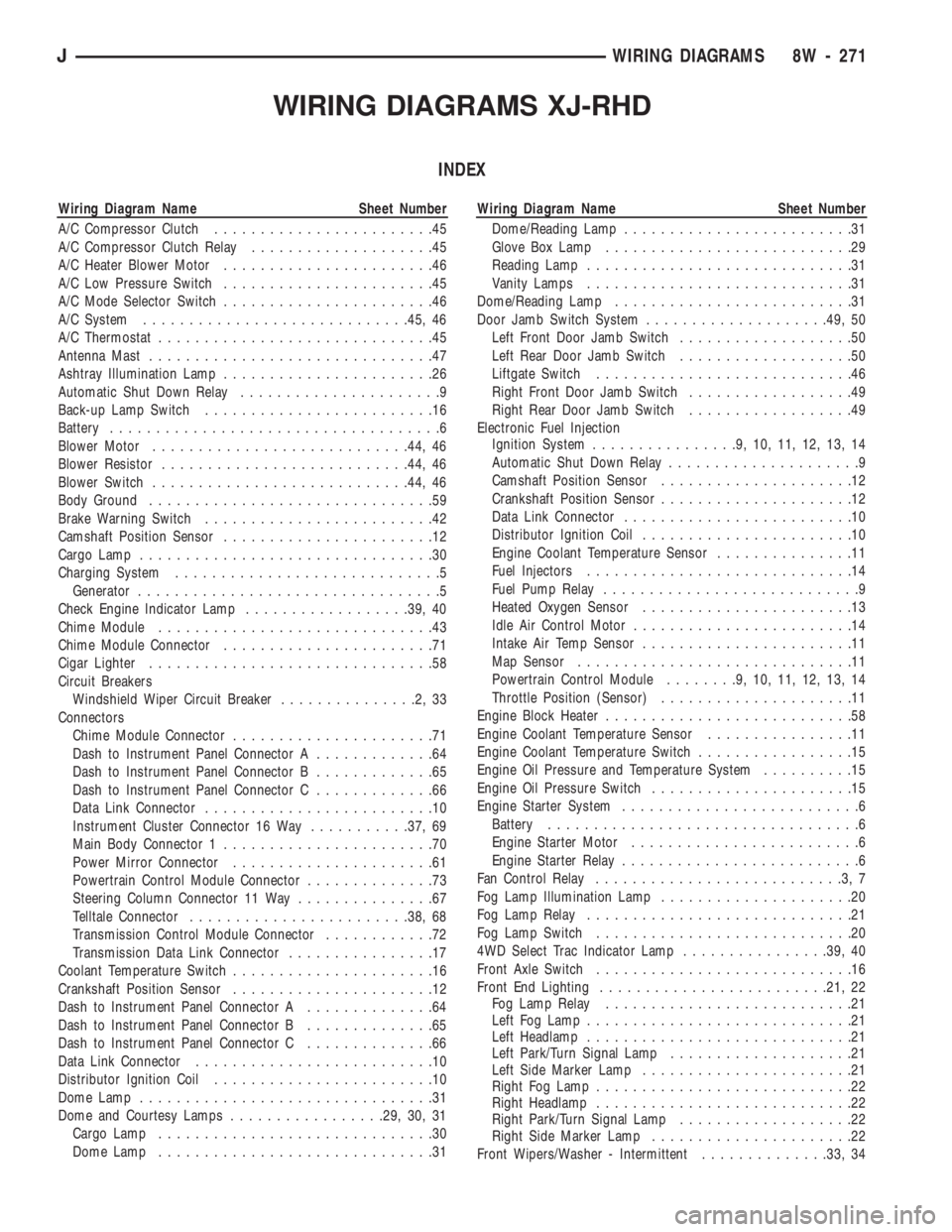
Wiring Diagram Name Sheet Number
A/C Compressor Clutch........................45
A/C Compressor Clutch Relay....................45
A/C Heater Blower Motor.......................46
A/C Low Pressure Switch.......................45
A/C Mode Selector Switch.......................46
A/C System.............................45, 46
A/C Thermostat..............................45
Antenna Mast...............................47
Ashtray Illumination Lamp.......................26
Automatic Shut Down Relay......................9
Back-up Lamp Switch.........................16
Battery....................................6
Blower Motor............................44, 46
Blower Resistor...........................44, 46
Blower Switch............................44, 46
Body Ground...............................59
Brake Warning Switch.........................42
Camshaft Position Sensor.......................12
Cargo Lamp................................30
Charging System.............................5
Generator.................................5
Check Engine Indicator Lamp..................39, 40
Chime Module..............................43
Chime Module Connector.......................71
Cigar Lighter...............................58
Circuit Breakers
Windshield Wiper Circuit Breaker...............2,33
Connectors
Chime Module Connector......................71
Dash to Instrument Panel Connector A.............64
Dash to Instrument Panel Connector B.............65
Dash to Instrument Panel Connector C.............66
Data Link Connector.........................10
Instrument Cluster Connector 16 Way...........37, 69
Main Body Connector 1.......................70
Power Mirror Connector......................61
Powertrain Control Module Connector..............73
Steering Column Connector 11 Way...............67
Telltale Connector........................38, 68
Transmission Control Module Connector............72
Transmission Data Link Connector................17
Coolant Temperature Switch......................16
Crankshaft Position Sensor......................12
Dash to Instrument Panel Connector A..............64
Dash to Instrument Panel Connector B..............65
Dash to Instrument Panel Connector C..............66
Data Link Connector..........................10
Distributor Ignition Coil........................10
Dome Lamp................................31
Dome and Courtesy Lamps.................29, 30, 31
Cargo Lamp..............................30
Dome Lamp..............................31