JEEP WRANGLER 1994 Owners Manual
WRANGLER 1994
JEEP
JEEP
https://www.carmanualsonline.info/img/16/56045/w960_56045-0.png
JEEP WRANGLER 1994 Owners Manual
Trending: park assist, trunk, height adjustment, fuel pressure, belt, radiator cap, drain bolt
Page 931 of 1770
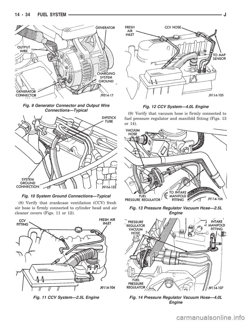
(8) Verify that crankcase ventilation (CCV) fresh
air hose is firmly connected to cylinder head and air
cleaner covers (Figs. 11 or 12).(9) Verify that vacuum hose is firmly connected to
fuel pressure regulator and manifold fitting (Figs. 13
or 14).
Fig. 9 Generator Connector and Output Wire
ConnectionsÐTypical
Fig. 10 System Ground ConnectionsÐTypical
Fig. 11 CCV SystemÐ2.5L Engine
Fig. 12 CCV SystemÐ4.0L Engine
Fig. 13 Pressure Regulator Vacuum HoseÐ2.5L
Engine
Fig. 14 Pressure Regulator Vacuum HoseÐ4.0L
Engine
14 - 34 FUEL SYSTEMJ
Page 932 of 1770
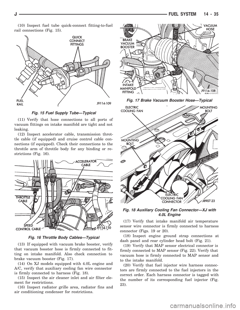
(10) Inspect fuel tube quick-connect fitting-to-fuel
rail connections (Fig. 15).
(11) Verify that hose connections to all ports of
vacuum fittings on intake manifold are tight and not
leaking.
(12) Inspect accelerator cable, transmission throt-
tle cable (if equipped) and cruise control cable con-
nections (if equipped). Check their connections to the
throttle arm of throttle body for any binding or re-
strictions (Fig. 16).
(13) If equipped with vacuum brake booster, verify
that vacuum booster hose is firmly connected to fit-
ting on intake manifold. Also check connection to
brake vacuum booster (Fig. 17).
(14) On XJ models equipped with 4.0L engine and
A/C, verify that auxiliary cooling fan wire connector
is firmly connected to harness (Fig. 18).
(15) Inspect the air cleaner inlet and air filter ele-
ment for restrictions.
(16) Inspect radiator grille area, radiator fins and
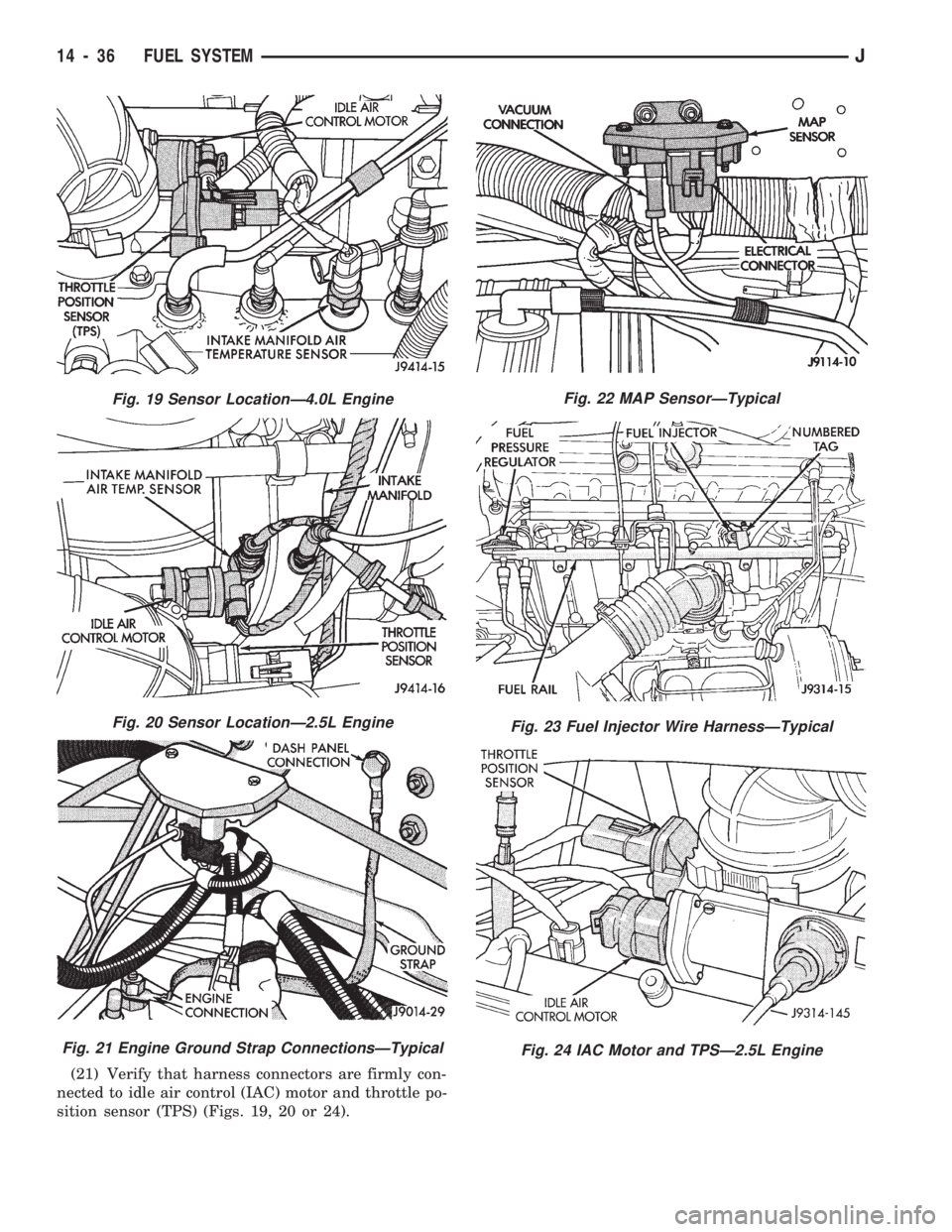
air conditioning condenser for restrictions.(17) Verify that intake manifold air temperature
sensor wire connector is firmly connected to harness
connector (Figs. 19 or 20).
(18) Inspect engine ground strap connections at
dash panel and rear cylinder head bolt (Fig. 21).
(19) Verify that MAP sensor electrical connector is
firmly connected to MAP sensor (Fig. 22). Verify that
vacuum hose is firmly connected to MAP sensor and
to the intake manifold.
(20) Verify that fuel injector wire harness connec-
tors are firmly connected to the fuel injectors in the
correct order. Each harness connector is tagged with
the number of its corresponding fuel injector (Fig.
23).
Fig. 15 Fuel Supply TubeÐTypical
Fig. 16 Throttle Body CablesÐTypical
Fig. 17 Brake Vacuum Booster HoseÐTypical
Fig. 18 Auxiliary Cooling Fan ConnectorÐXJ with
4.0L Engine
JFUEL SYSTEM 14 - 35
Page 933 of 1770
(21) Verify that harness connectors are firmly con-
nected to idle air control (IAC) motor and throttle po-
sition sensor (TPS) (Figs. 19, 20 or 24).
Fig. 19 Sensor LocationÐ4.0L Engine
Fig. 20 Sensor LocationÐ2.5L Engine
Fig. 21 Engine Ground Strap ConnectionsÐTypical
Fig. 22 MAP SensorÐTypical
Fig. 23 Fuel Injector Wire HarnessÐTypical
Fig. 24 IAC Motor and TPSÐ2.5L Engine
14 - 36 FUEL SYSTEMJ
Page 934 of 1770
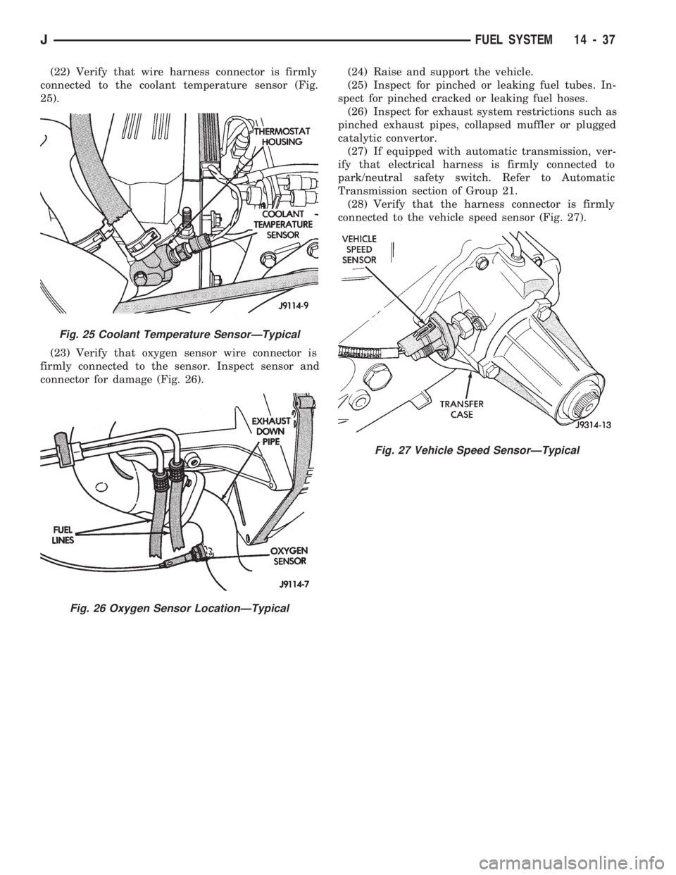
(22) Verify that wire harness connector is firmly
connected to the coolant temperature sensor (Fig.
25).
(23) Verify that oxygen sensor wire connector is
firmly connected to the sensor. Inspect sensor and
connector for damage (Fig. 26).(24) Raise and support the vehicle.
(25) Inspect for pinched or leaking fuel tubes. In-
spect for pinched cracked or leaking fuel hoses.
(26) Inspect for exhaust system restrictions such as
pinched exhaust pipes, collapsed muffler or plugged
catalytic convertor.
(27) If equipped with automatic transmission, ver-
ify that electrical harness is firmly connected to
park/neutral safety switch. Refer to Automatic
Transmission section of Group 21.
(28) Verify that the harness connector is firmly
connected to the vehicle speed sensor (Fig. 27).
Fig. 25 Coolant Temperature SensorÐTypical
Fig. 26 Oxygen Sensor LocationÐTypical
Fig. 27 Vehicle Speed SensorÐTypical
JFUEL SYSTEM 14 - 37
Page 935 of 1770
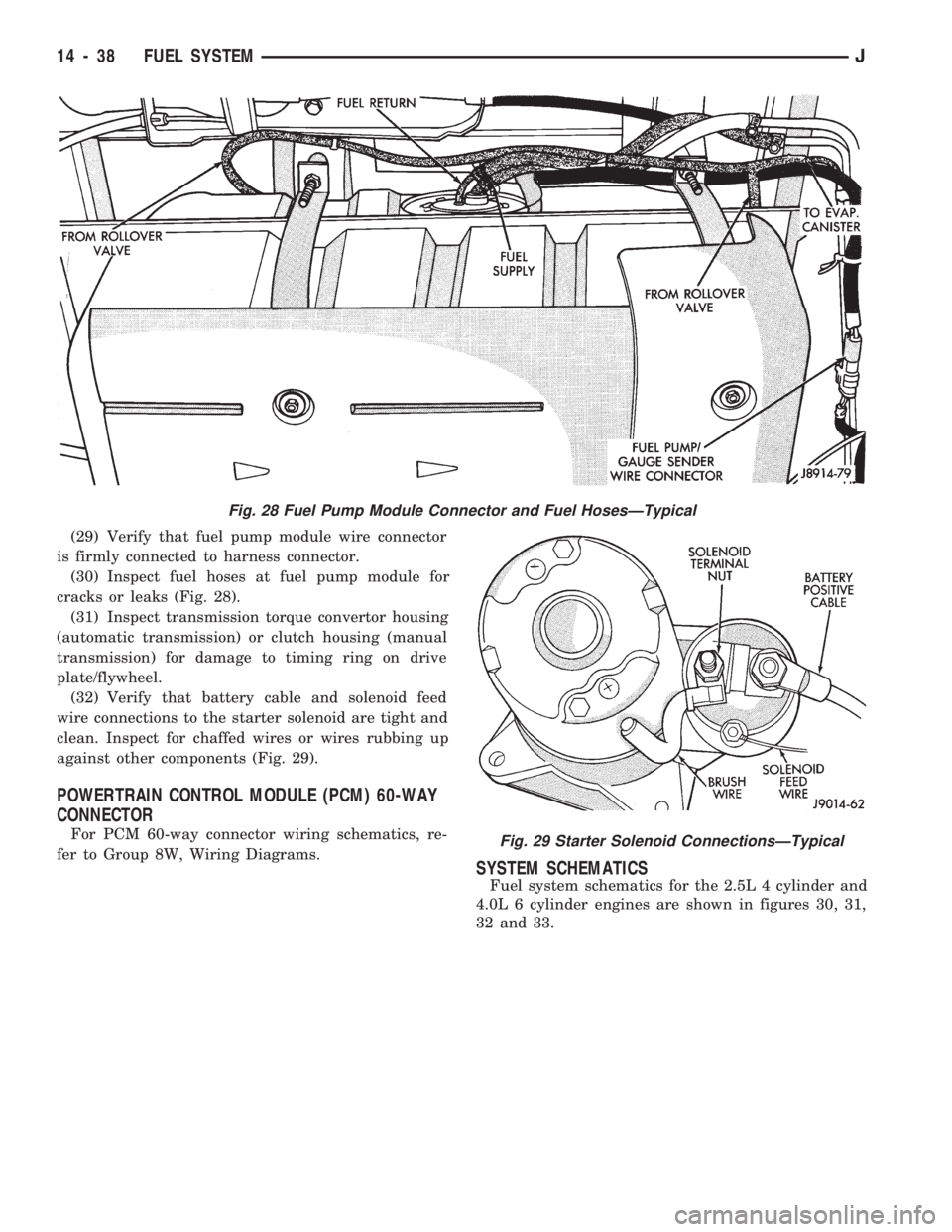
(29) Verify that fuel pump module wire connector
is firmly connected to harness connector.
(30) Inspect fuel hoses at fuel pump module for
cracks or leaks (Fig. 28).
(31) Inspect transmission torque convertor housing
(automatic transmission) or clutch housing (manual
transmission) for damage to timing ring on drive
plate/flywheel.
(32) Verify that battery cable and solenoid feed
wire connections to the starter solenoid are tight and
clean. Inspect for chaffed wires or wires rubbing up
against other components (Fig. 29).
POWERTRAIN CONTROL MODULE (PCM) 60-WAY
CONNECTOR
For PCM 60-way connector wiring schematics, re-
fer to Group 8W, Wiring Diagrams.
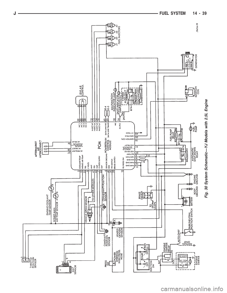
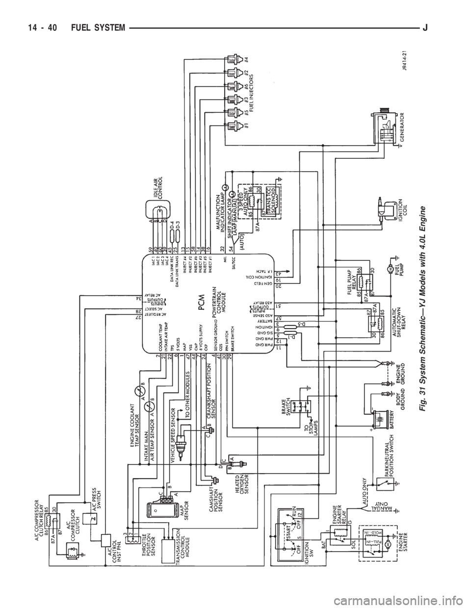
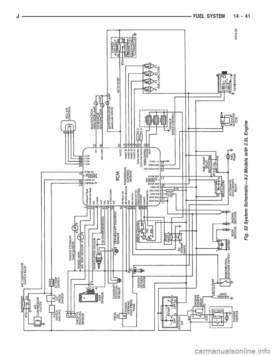
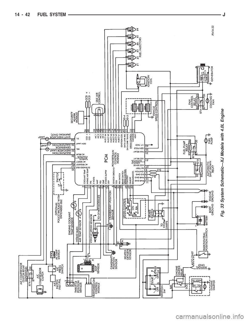
SYSTEM SCHEMATICS
Fuel system schematics for the 2.5L 4 cylinder and
4.0L 6 cylinder engines are shown in figures 30, 31,
32 and 33.
Fig. 28 Fuel Pump Module Connector and Fuel HosesÐTypical
Fig. 29 Starter Solenoid ConnectionsÐTypical
14 - 38 FUEL SYSTEMJ
Page 936 of 1770
Fig. 30 System SchematicÐYJ Models with 2.5L Engine
JFUEL SYSTEM 14 - 39
Page 937 of 1770
Fig. 31 System SchematicÐYJ Models with 4.0L Engine
14 - 40 FUEL SYSTEMJ
Page 938 of 1770
Fig. 32 System SchematicÐXJ Models with 2.5L Engine
JFUEL SYSTEM 14 - 41
Page 939 of 1770
Fig. 33 System SchematicÐXJ Models with 4.0L Engine
14 - 42 FUEL SYSTEMJ
Page 940 of 1770
AUTOMATIC SHUT DOWN (ASD) RELAY TESTING
To perform a complete test of the ASD relay and
its circuitry, refer to the DRB scan tool and appropri-
ate Powertrain Diagnostics Procedures manual. To
test the relay only, refer to RelaysÐOperation/Test-
ing in this section of the group.
CAMSHAFT POSITION SENSOR TEST
Refer to Group 8D, Ignition Systems, for Camshaft
Position Sensor testing.
ENGINE COOLANT TEMPERATURE SENSOR TEST
To perform a complete test of the engine coolant
temperature sensor and its circuitry, refer to DRB
scan tool and appropriate Powertrain Diagnostics
Procedures manual. To test the sensor only, refer to
the following:
Disconnect wire harness connector from engine
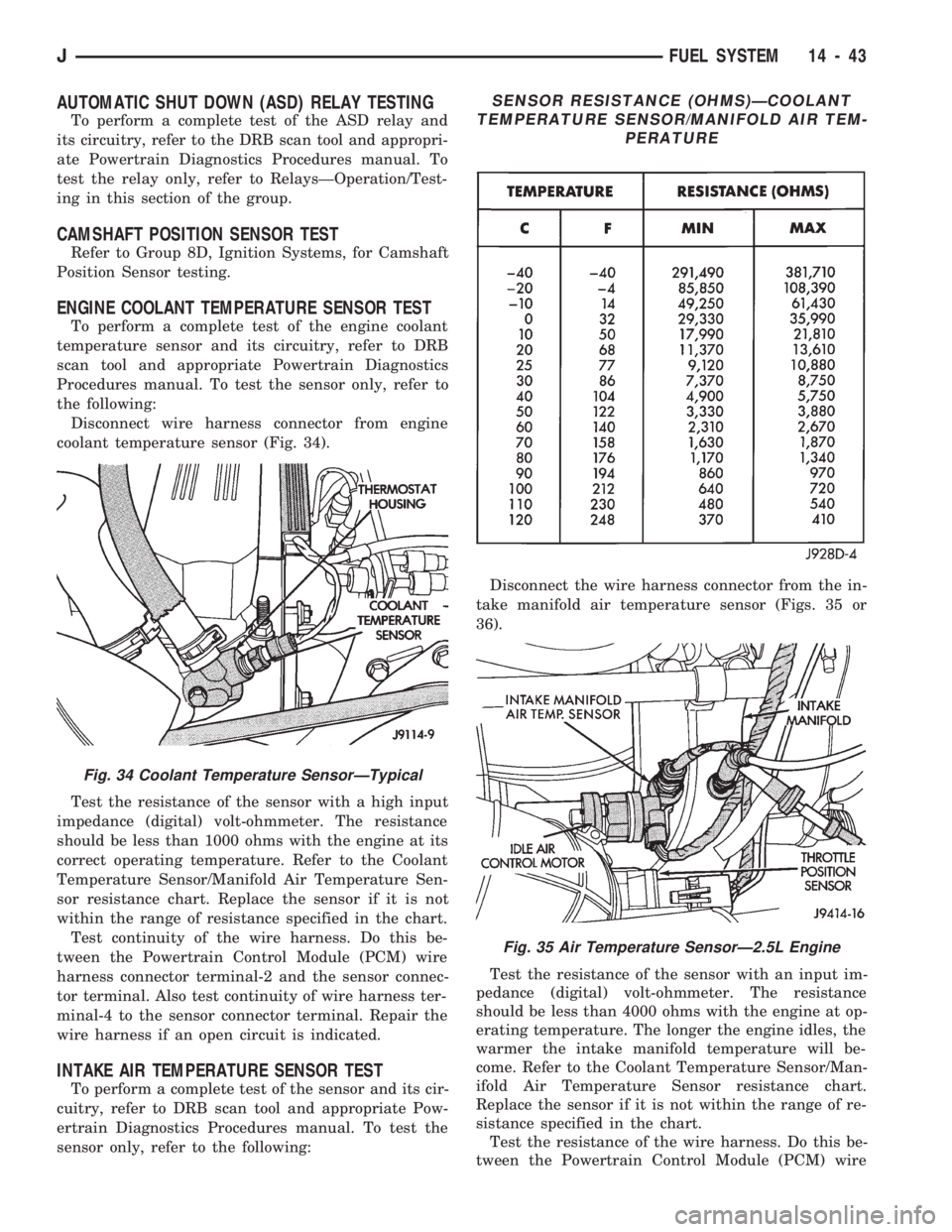
coolant temperature sensor (Fig. 34).
Test the resistance of the sensor with a high input
impedance (digital) volt-ohmmeter. The resistance
should be less than 1000 ohms with the engine at its
correct operating temperature. Refer to the Coolant
Temperature Sensor/Manifold Air Temperature Sen-
sor resistance chart. Replace the sensor if it is not
within the range of resistance specified in the chart.
Test continuity of the wire harness. Do this be-
tween the Powertrain Control Module (PCM) wire
harness connector terminal-2 and the sensor connec-
tor terminal. Also test continuity of wire harness ter-
minal-4 to the sensor connector terminal. Repair the
wire harness if an open circuit is indicated.
INTAKE AIR TEMPERATURE SENSOR TEST
To perform a complete test of the sensor and its cir-
cuitry, refer to DRB scan tool and appropriate Pow-
ertrain Diagnostics Procedures manual. To test the
sensor only, refer to the following:Disconnect the wire harness connector from the in-
take manifold air temperature sensor (Figs. 35 or
36).
Test the resistance of the sensor with an input im-
pedance (digital) volt-ohmmeter. The resistance
should be less than 4000 ohms with the engine at op-
erating temperature. The longer the engine idles, the
warmer the intake manifold temperature will be-
come. Refer to the Coolant Temperature Sensor/Man-
ifold Air Temperature Sensor resistance chart.
Replace the sensor if it is not within the range of re-
sistance specified in the chart.
Test the resistance of the wire harness. Do this be-
tween the Powertrain Control Module (PCM) wire
Fig. 34 Coolant Temperature SensorÐTypical
SENSOR RESISTANCE (OHMS)ÐCOOLANT
TEMPERATURE SENSOR/MANIFOLD AIR TEM-
PERATURE
Fig. 35 Air Temperature SensorÐ2.5L Engine
JFUEL SYSTEM 14 - 43
Trending: mirror, relay, headlamp, change key battery, warning light, flat tire, tailgate
