brake sensor JEEP WRANGLER 1995 Owners Manual
[x] Cancel search | Manufacturer: JEEP, Model Year: 1995, Model line: WRANGLER, Model: JEEP WRANGLER 1995Pages: 2158, PDF Size: 81.01 MB
Page 164 of 2158
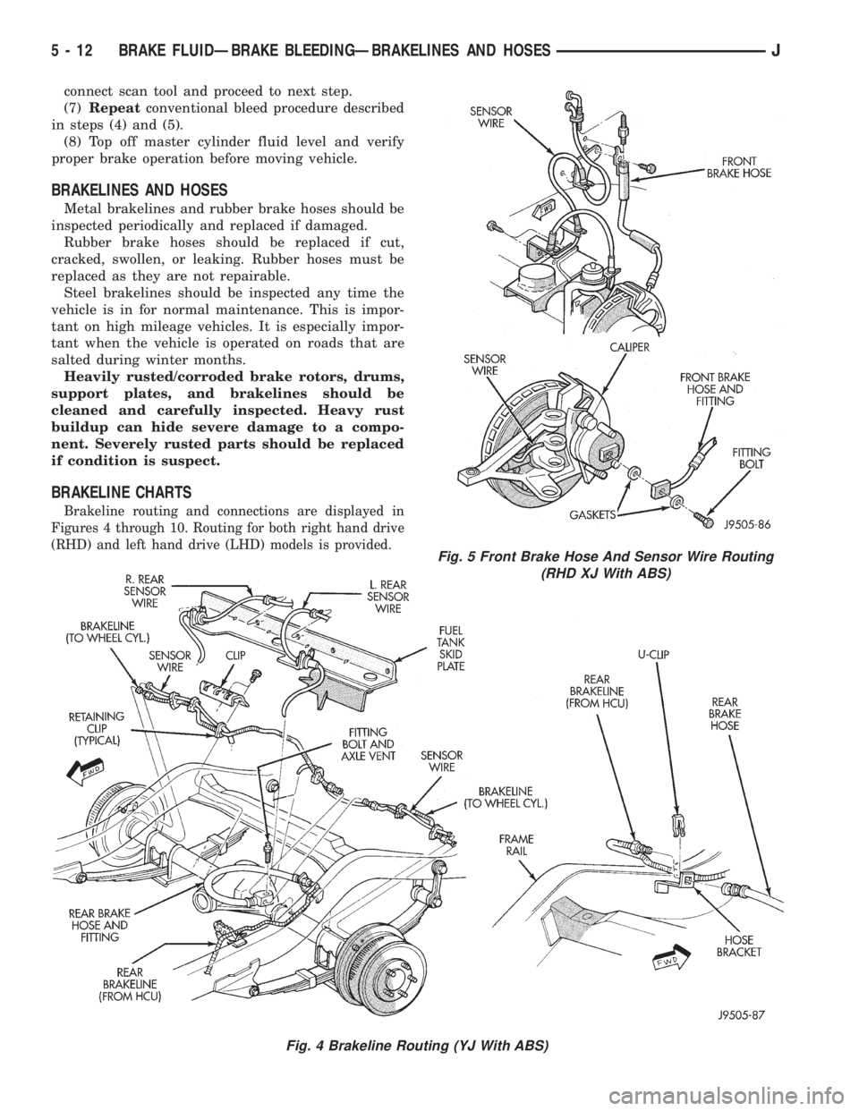
Fig. 5 Front Brake Hose And Sensor Wire Routing
(RHD XJ With ABS)
5 - 12 BRAKE FLUIDÐBRAKE BLEEDINGÐBRAKELINES AND HOSESJ
Page 615 of 2158
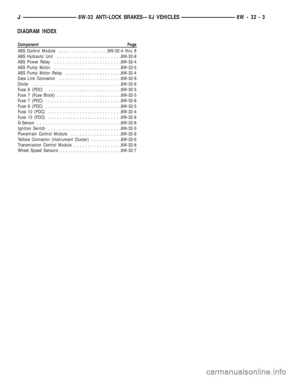
Component Page
ABS Control Module..................8W-32-4 thru 8
ABS Hydraulic Unit.......................8W-32-6
ABS Power Relay........................8W-32-4
ABS Pump Motor........................8W-32-5
ABS Pump Motor Relay....................8W-32-4
Data Link Connector......................8W-32-8
Diode................................8W-32-6
Fuse 6 (PDC)...........................8W-32-5
Fuse 7 (Fuse Block).......................8W-32-5
Fuse 7 (PDC)...........................8W-32-8
Fuse 8 (PDC)...........................8W-32-5
Fuse 10 (PDC)..........................8W-32-4
Fuse 13 (PDC)..........................8W-32-8
G-Sensor..............................8W-32-8
Ignition Switch..........................8W-32-5
Powertrain Control Module..................8W-32-8
Telltale Connector (Instrument Cluster)...........8W-32-6
Transmission Control Module.................8W-32-8
Wheel Speed Sensors......................8W-32-7
J8W-32 ANTI-LOCK BRAKESÐXJ VEHICLES 8W - 32 - 3
Page 879 of 2158
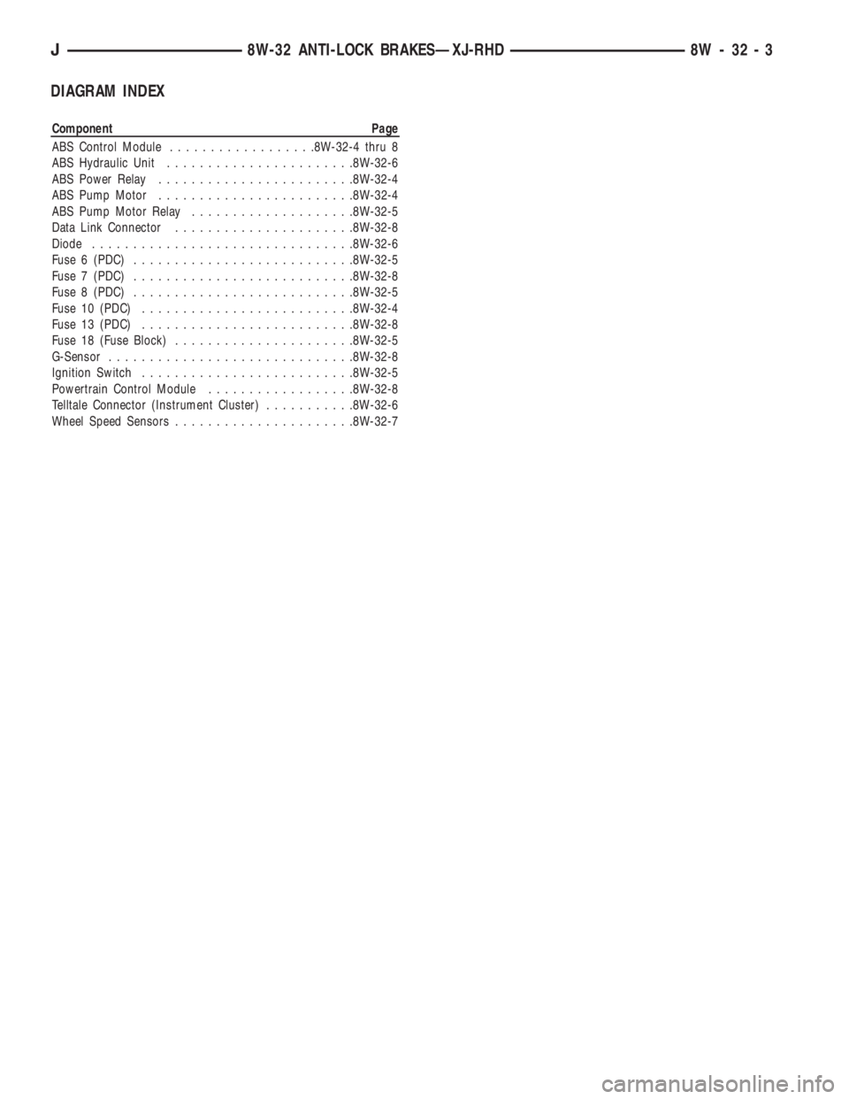
Component Page
ABS Control Module..................8W-32-4 thru 8
ABS Hydraulic Unit.......................8W-32-6
ABS Power Relay........................8W-32-4
ABS Pump Motor........................8W-32-4
ABS Pump Motor Relay....................8W-32-5
Data Link Connector......................8W-32-8
Diode................................8W-32-6
Fuse 6 (PDC)...........................8W-32-5
Fuse 7 (PDC)...........................8W-32-8
Fuse 8 (PDC)...........................8W-32-5
Fuse 10 (PDC)..........................8W-32-4
Fuse 13 (PDC)..........................8W-32-8
Fuse 18 (Fuse Block)......................8W-32-5
G-Sensor..............................8W-32-8
Ignition Switch..........................8W-32-5
Powertrain Control Module..................8W-32-8
Telltale Connector (Instrument Cluster)...........8W-32-6
Wheel Speed Sensors......................8W-32-7
J8W-32 ANTI-LOCK BRAKESÐXJ-RHD 8W - 32 - 3
Page 1085 of 2158
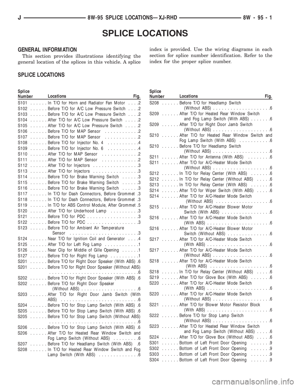
Splice
NumberLocations Fig.
S101......InT/OforHorn and Radiator Fan Motor....2
S102......Before T/O for A/C Low Pressure Switch....2
S103......Before T/O for A/C Low Pressure Switch....2
S104......After T/O for A/C Low Pressure Switch.....2
S105......After T/O for A/C Low Pressure Switch.....2
S106......Before T/O for MAP Sensor............2
S107......Before T/O for MAP Sensor............2
S108......Before T/O for Injector No. 4...........4
S109......Before T/O for Injector No. 6...........4
S110......After T/O for MAP Sensor.............2
S111......After T/O for MAP Sensor.............2
S112......After T/O for Injectors................3
S113......After T/O for Injectors................3
S114......Before T/O for Brake Warning Switch......3
S115......Before T/O for Brake Warning Switch......3
S116......Before T/O for Brake Warning Switch......3
S117......InT/OforDash Connectors, Before Grommet .3
S118......InT/OforDash Connectors, Before Grommet .3
S119......InT/OforABSControl Module, After Grommet .5
S120......After T/O for Underhood Lamp..........3
S121......Before T/O for PDC..................3
S122......Before T/O for PDC..................3
S123......Before T/O for Ambient Air Temperature
Sensor........................3
S124......Near T/O for Ignition Coil and Generator....4
S125......After T/O for Left Fog Lamp............1
S126......Near Clip for Middle of Gille Opening......1
S127......Before T/O for Right Fog Lamp..........1
S201......Before T/O for Right Door Speaker (With ABS) .6
S201......Before T/O for Right Door Speaker (Without ABS)
...............................6
S202......Before T/O for Right Door Speaker (With ABS) .6
S202......Before T/O for Right Door Speaker
(Without ABS)....................6
S203......After T/O for Right Door Jamb Switch (With
ABS)...........................6
S204......Before T/O for Stop Lamp Switch (With ABS) .6
S205......Before T/O for Stop Lamp Switch (With ABS) .6
S205......Before T/O for Stop Lamp Switch (Without ABS)
...............................6
S206......Before T/O for Stop Lamp Switch (With ABS) .6
S206......After T/O for Heated Rear Window Switch and
Fog Lamp Switch (Without ABS).........6
S207......Before T/O for Headlamp Switch (With ABS) .6
S208......InT/OforHeated Rear Window Switch and Fog
Lamp Switch (With ABS)..............6
Page 1147 of 2158
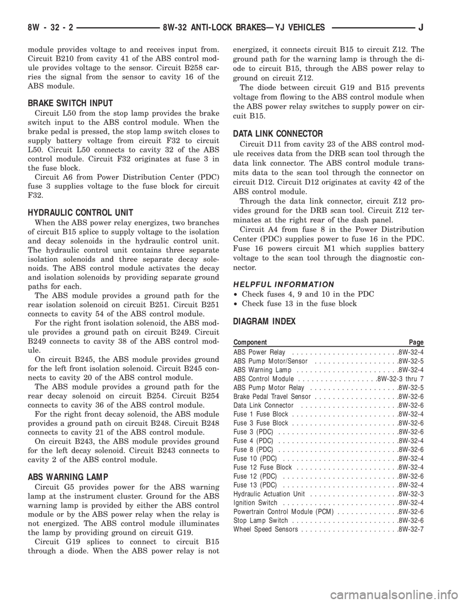
Component Page
ABS Power Relay........................8W-32-4
ABS Pump Motor/Sensor...................8W-32-5
ABS Warning Lamp.......................8W-32-4
ABS Control Module..................8W-32-3 thru 7
ABS Pump Motor Relay....................8W-32-5
Brake Pedal Travel Sensor...................8W-32-6
Data Link Connector......................8W-32-6
Fuse 1 Fuse Block........................8W-32-4
Fuse 3 Fuse Block........................8W-32-6
Fuse 3 (PDC)...........................8W-32-6
Fuse 4 (PDC)...........................8W-32-4
Fuse 8 (PDC)...........................8W-32-6
Fuse 10 (PDC)..........................8W-32-4
Fuse 12 Fuse Block.......................8W-32-4
Fuse 12 (PDC)..........................8W-32-6
Fuse 13 (PDC)..........................8W-32-4
Hydraulic Actuation Unit....................8W-32-3
Ignition Switch..........................8W-32-4
Powertrain Control Module (PCM)..............8W-32-6
Stop Lamp Switch........................8W-32-6
Wheel Speed Sensors......................8W-32-7
8W - 32 - 2 8W-32 ANTI-LOCK BRAKESÐYJ VEHICLESJ
Page 1155 of 2158
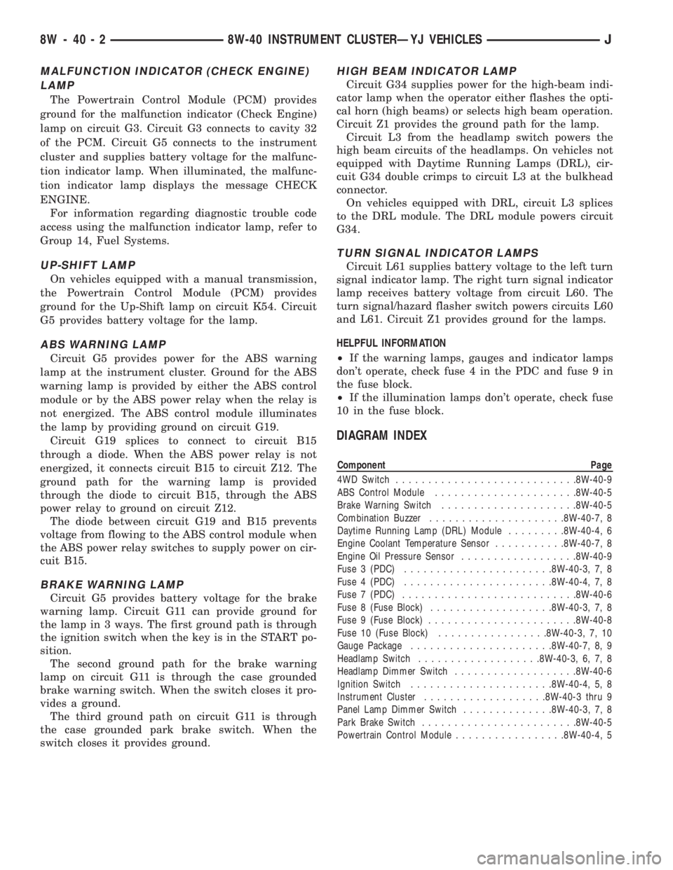
Component Page
4WD Switch............................8W-40-9
ABS Control Module......................8W-40-5
Brake Warning Switch.....................8W-40-5
Combination Buzzer.....................8W-40-7, 8
Daytime Running Lamp (DRL) Module.........8W-40-4, 6
Engine Coolant Temperature Sensor...........8W-40-7, 8
Engine Oil Pressure Sensor..................8W-40-9
Fuse 3 (PDC).......................8W-40-3, 7, 8
Fuse 4 (PDC).......................8W-40-4, 7, 8
Fuse 7 (PDC)...........................8W-40-6
Fuse 8 (Fuse Block)...................8W-40-3, 7, 8
Fuse 9 (Fuse Block).......................8W-40-8
Fuse 10 (Fuse Block).................8W-40-3, 7, 10
Gauge Package......................8W-40-7, 8, 9
Headlamp Switch...................8W-40-3, 6, 7, 8
Headlamp Dimmer Switch...................8W-40-6
Ignition Switch......................8W-40-4, 5, 8
Instrument Cluster...................8W-40-3 thru 9
Panel Lamp Dimmer Switch..............8W-40-3, 7, 8
Park Brake Switch........................8W-40-5
Powertrain Control Module.................8W-40-4, 5
8W - 40 - 2 8W-40 INSTRUMENT CLUSTERÐYJ VEHICLESJ
Page 1262 of 2158
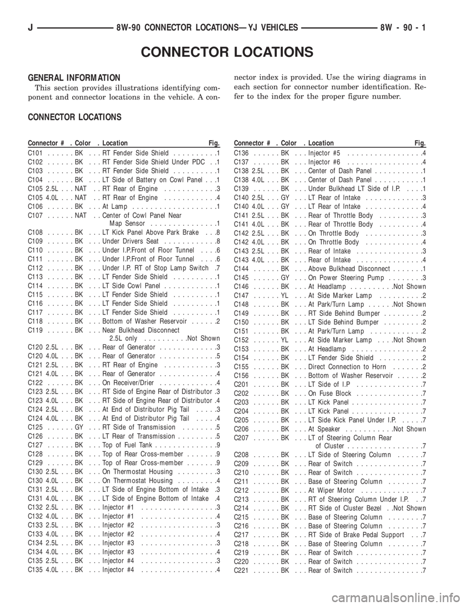
Connector # . Color . Location Fig.
C101......BK ...RTFender Side Shield..........1
C102......BK ...RTFender Side Shield Under PDC . .1
C103......BK ...RTFender Side Shield..........1
C104......BK ...LTSide of Battery on Cowl Panel . . .1
C105 2.5L . . . NAT . . RT Rear of Engine............3
C105 4.0L . . . NAT . . RT Rear of Engine............4
C106......BK ...AtLamp...................1
C107......NAT ..Center of Cowl Panel Near
Map Sensor...............1
C108......BK ...LTKick Panel Above Park Brake . . .8
C109......BK ...Under Drivers Seat............8
C110......BK ...Under I.P.Front of Floor Tunnel....6
C111......BK ...Under I.P.Front of Floor Tunnel....6
C112......BK ...Under I.P. RT of Stop Lamp Switch .7
C113......BK ...LTFender Side Shield..........1
C114......BK ...LTSide Cowl Panel............1
C115......BK ...LTFender Side Shield..........1
C116......BK ...LTFender Side Shield..........1
C117......BK ...LTFender Side Shield..........1
C118......BK ...Bottom of Washer Reservoir......2
C119......BK ...Near Bulkhead Disconnect
2.5L only..........Not Shown
C120 2.5L . . . BK . . . Rear of Generator.............3
C120 4.0L . . . BK . . . Rear of Generator.............5
C121 2.5L . . . BK . . . RT Rear of Engine............3
C121 4.0L . . . BK . . . Rear of Generator.............4
C122......BK ...OnReceiver/Drier.............4
C123 2.5L . . . BK . . . RT Side of Engine Rear of Distributor .3
C123 4.0L . . . BK . . . RT Side of Engine Rear of Distributor .4
C124 2.5L . . . BK . . . At End of Distributor Pig Tail.....3
C124 4.0L . . . BK . . . At End of Distributor Pig Tail.....4
C125......GY ...RTSide of Transmission........5
C126......BK ...LTRear of Transmission.........5
C127......BK ...TopofFuel Tank..............9
C128......BK ...TopofRear Cross-member.......9
C129......BK ...TopofRear Cross-member.......9
C130 2.5L . . . BK . . . On Thermostat Housing.........3
C130 4.0L . . . BK . . . On Thermostat Housing.........4
C131 2.5L . . . BK . . . LT Side of Engine Bottom of Intake .3
C131 4.0L . . . BK . . . LT Side of Engine Bottom of Intake .4
C132 2.5L . . . BK . . . Injector #1.................3
C132 4.0L . . . BK . . . Injector #1.................4
C133 2.5L . . . BK . . . Injector #2.................3
C133 4.0L . . . BK . . . Injector #2.................4
C134 2.5L . . . BK . . . Injector #3.................3
C134 4.0L . . . BK . . . Injector #3.................4
C135 2.5L . . . BK . . . Injector #4.................3
C135 4.0L . . . BK . . . Injector #4.................4
Page 1273 of 2158
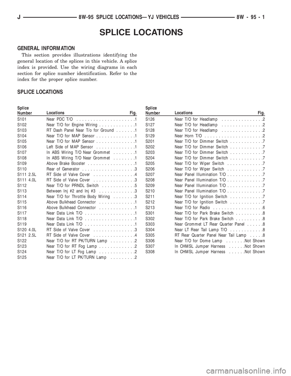
Splice
NumberLocations Fig.
S101 Near PDC T/O.....................1
S102 Near T/O for Engine Wiring.............1
S103 RT Dash Panel Near T/o for Ground.......1
S104 Near T/O for MAP Sensor..............1
S105 Near T/O for MAP Sensor..............1
S106 Left Side of MAP Sensor..............1
S107 In ABS Wiring T/O Near Grommet........1
S108 In ABS Wiring T/O Near Grommet........1
S109 Above Brake Booster.................1
S110 Rear of Generator...................3
S111 2.5L RT Side of Valve Cover...............4
S111 4.0L RT Side of Valve Cover...............3
S112 Near T/O for PRNDL Switch............5
S113 Between Inj #2 and Inj #3.............3
S114 Near T/O for Throttle Body Wiring........3
S115 Above Bulkhead Connector.............1
S116 Above Bulkhead Connector.............1
S117 Near Data Link T/O..................1
S118 Near Data Link T/O..................1
S119 Near Data Link T/O..................1
S120 4.0L RT Side of Valve Cover...............3
S121 2.5L RT Side of Valve Cover...............4
S122 Near T/O for RT PK/TURN Lamp.........2
S123 Near T/O for RT Fog Lamp.............2
S124 Near T/O for LT Fog Lamp.............2
S125 Near T/O for LT PK/TURN Lamp.........2
Page 1440 of 2158
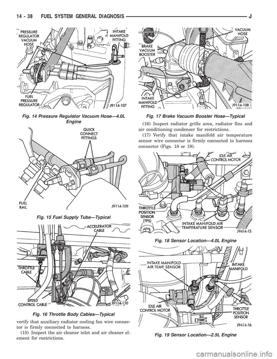
Fig. 15 Fuel Supply TubeÐTypical
Fig. 16 Throttle Body CablesÐTypical
Fig. 17 Brake Vacuum Booster HoseÐTypical
Fig. 18 Sensor LocationÐ4.0L Engine
Fig. 19 Sensor LocationÐ2.5L Engine
14 - 38 FUEL SYSTEM GENERAL DIAGNOSISJ