driver JEEP WRANGLER 2009 JK / 3.G Service Manual
[x] Cancel search | Manufacturer: JEEP, Model Year: 2009, Model line: WRANGLER, Model: JEEP WRANGLER 2009 JK / 3.GPages: 502, PDF Size: 14.47 MB
Page 208 of 502
21. Odometer / Trip Odometer Reset Button
Press this button to change the display from odometer to
either of the two trip odometer settings. Trip A or Trip B
will appear when in the trip odometer mode. Press and
hold the button for two seconds to reset the trip odometer
to 0 miles or kilometers. The odometer must be in trip
mode to reset.
22. Shift Lever Indicator
The Shift Lever Indicator is self-contained within the
instrument cluster. It displays the gear position of the
automatic transmission.
23. Tire Pressure Monitoring Telltale LightEach tire, including the spare (if provided),
should be checked monthly, when cold and
inflated to the inflation pressure recommended
by the vehicle manufacturer on the vehicle placard or tire
inflation pressure label. (If your vehicle has tires of a
different size than the size indicated on the vehicle placard or tire inflation pressure label, you should deter-
mine the proper tire inflation pressure for those tires.)
As an added safety feature, your vehicle has been
equipped with a Tire Pressure Monitoring System
(TPMS) that illuminates a low tire pressure telltale when
one or more of your tires is significantly under-inflated.
Accordingly, when the low tire pressure telltale illumi-
nates, you should stop and check your tires as soon as
possible, and inflate them to the proper pressure. Driving
on a significantly under-inflated tire causes the tire to
overheat and can lead to tire failure. Under-inflation also
reduces fuel efficiency and tire tread life, and may affect
the vehicle’s handling and stopping ability.
Please note that the TPMS is not a substitute for proper
tire maintenance, and it is the driver ’s responsibility to
maintain correct tire pressure, even if under-inflation has
not reached the level to trigger illumination of the TPMS
low tire pressure telltale.
206 UNDERSTANDING YOUR INSTRUMENT PANEL
Page 212 of 502
NOTE:If the indicator message illuminates when you
start the vehicle, the oil change indicator system did not
reset. If necessary repeat this procedure.
25. Malfunction Indicator Light (MIL) The Malfunction Indicator Light (MIL) is a part of
an Onboard Diagnostic System called OBD II that
monitors engine and automatic transmission con-
trol systems. The light will illuminate when the ignition
is in the ON position, before engine start. If the bulb does
not come on when turning the key from OFF to ON, have
the condition checked promptly.
Certain conditions such as a loose or missing gas cap,
poor quality fuel, etc. may illuminate the light after
engine start. The vehicle should be serviced if the light
stays on through several typical driving styles. In most
situations, the vehicle will drive normally and will not
require towing.CAUTION!
Prolonged driving with the MIL on could cause
damage to the engine control system. It also could
affect fuel economy and drivability. If the MIL is
flashing, severe catalytic converter damage and
power loss will soon occur. Immediate service is
required.
WARNING!
A malfunctioning catalytic converter, as referenced
above, can reach higher temperatures than in normal
operating conditions. This can cause a fire if you
drive slowly or park over flammable substances such
as dry plants or wood or cardboard, etc. This could
result in death or serious injury to the driver, occu-
pants or others.
210 UNDERSTANDING YOUR INSTRUMENT PANEL
Page 213 of 502
26.Electronic Stability Program (ESP) Indicator Light /
Traction Control System (TCS) Indicator Light
If the Electronic Stability Program (ESP) /
Traction Control System (TCS) Indicator Light
begins to flash during acceleration, ease up on
the accelerator and apply as little throttle as
possible. This indicator light starts to flash as soon as the
tires lose traction and the Electronic Stability Program
(ESP) becomes active. The ESP/TCS Indicator Light also
flashes when TCS is active. Be sure to adapt your speed
and driving to the prevailing road conditions. If the
ESP/TCS Indicator Light is on solid, the ESP system has
been turned off by the driver or a temporary condition
exists that will not allow full ESP function.
27. O/D (Overdrive) Off Indicator Light This light will illuminate when the O/D OFF
button has been selected and overdrive has been
turned off. The O/D OFF button is located on the center
console. 28. Sway Bar Indicator Light — If Equipped
This indicator will illuminate when the front
sway bar is disconnected.
29. Electronic Stability Program (ESP) / Brake Assist
System (BAS) Warning Light The Electronic Stability Program (ESP) / Brake
Assist System (BAS) warning light in the in-
strument cluster comes on when the ignition
switch is turned to the ON position. The light
should go out with the engine running. If the ESP/BAS
warning light comes on continuously with the engine
running, a malfunction has been detected in either the
ESP or the BAS system. If this light stays illuminated,
have the ESP and BAS checked at an authorized dealer as
soon as possible. Refer to “Electronic Brake Control
System” in Section 5 for more information.
4
UNDERSTANDING YOUR INSTRUMENT PANEL 211
Page 215 of 502
32. Compass / Mini-Trip Computer Button—If
Equipped
Press this button to switch between the different
functions.
COMPASS AND TRIP COMPUTER — IF
EQUIPPED
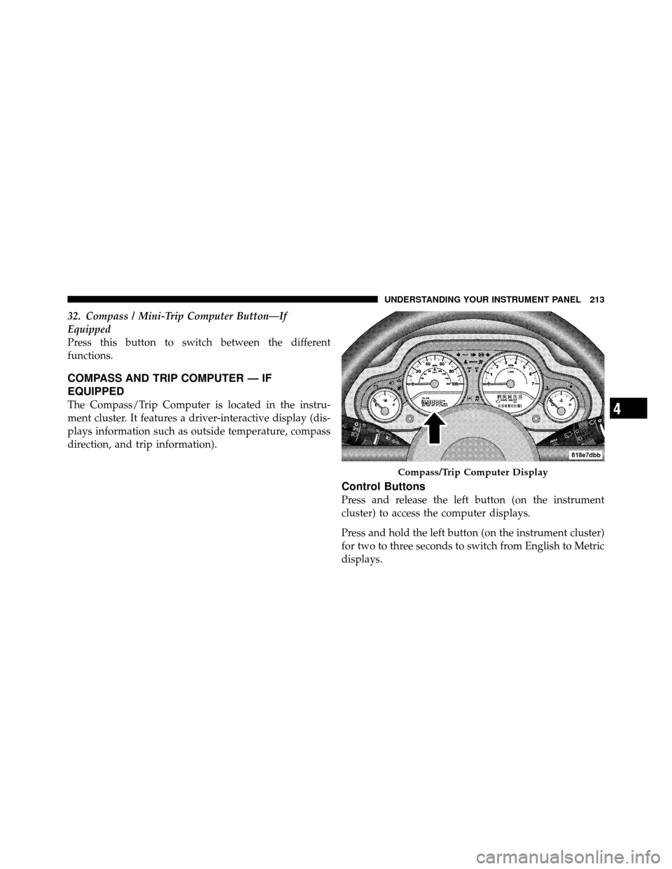
The Compass/Trip Computer is located in the instru-
ment cluster. It features a driver-interactive display (dis-
plays information such as outside temperature, compass
direction, and trip information).
Control Buttons
Press and release the left button (on the instrument
cluster) to access the computer displays.
Press and hold the left button (on the instrument cluster)
for two to three seconds to switch from English to Metric
displays.
Compass/Trip Computer Display
4
UNDERSTANDING YOUR INSTRUMENT PANEL 213
Page 283 of 502
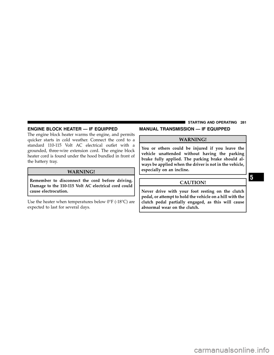
ENGINE BLOCK HEATER — IF EQUIPPED
The engine block heater warms the engine, and permits
quicker starts in cold weather. Connect the cord to a
standard 110-115 Volt AC electrical outlet with a
grounded, three-wire extension cord. The engine block
heater cord is found under the hood bundled in front of
the battery tray.
WARNING!
Remember to disconnect the cord before driving.
Damage to the 110-115 Volt AC electrical cord could
cause electrocution.
Use the heater when temperatures below 0°F (-18°C) are
expected to last for several days.
MANUAL TRANSMISSION — IF EQUIPPED
WARNING!
You or others could be injured if you leave the
vehicle unattended without having the parking
brake fully applied. The parking brake should al-
ways be applied when the driver is not in the vehicle,
especially on an incline.
CAUTION!
Never drive with your foot resting on the clutch
pedal, or attempt to hold the vehicle on a hill with the
clutch pedal partially engaged, as this will cause
abnormal wear on the clutch.
5
STARTING AND OPERATING 281
Page 286 of 502
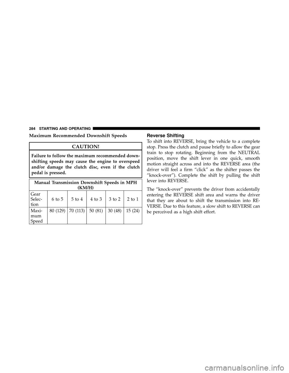
Maximum Recommended Downshift Speeds
CAUTION!
Failure to follow the maximum recommended down-
shifting speeds may cause the engine to overspeed
and/or damage the clutch disc, even if the clutch
pedal is pressed.
Manual Transmission Downshift Speeds in MPH(KM/H)
Gear
Selec-
tion 6to5 5to4 4to3 3to2 2to1
Maxi-
mum
Speed 80 (129) 70 (113) 50 (81) 30 (48) 15 (24)
Reverse Shifting
To shift into REVERSE, bring the vehicle to a complete
stop. Press the clutch and pause briefly to allow the gear
train to stop rotating. Beginning from the NEUTRAL
position, move the shift lever in one quick, smooth
motion straight across and into the REVERSE area (the
driver will feel a firm “click” as the shifter passes the
“knock-over”). Complete the shift by pulling the shift
lever into REVERSE.
The “knock-over” prevents the driver from accidentally
entering the REVERSE shift area and warns the driver
that they are about to shift the transmission into RE-
VERSE. Due to this feature, a slow shift to REVERSE can
be perceived as a high shift effort.
284 STARTING AND OPERATING
Page 288 of 502
Brake/Transmission Interlock System
This vehicle is equipped with a Brake Transmission Shift
Interlock System (BTSI) that holds the shift lever in the
PARK position when the ignition switch is in the LOCK
position. To move the shift lever out of the PARK
position, the ignition switch must be turned to any other
switch position (ACC, ON, or START) (engine running or
not) and the brake pedal must be pressed.
Brake/Transmission Interlock Manual Override
Your vehicle may be equipped with a shift lock manual
override. The manual override may be used in the event
that the shift lever should fail to move from PARK with
the key in the ON position and the brake pedal pressed.
To operate the shift lock manual override, perform the
following steps:
1. Turn the key to the ON position but do not start the
engine.
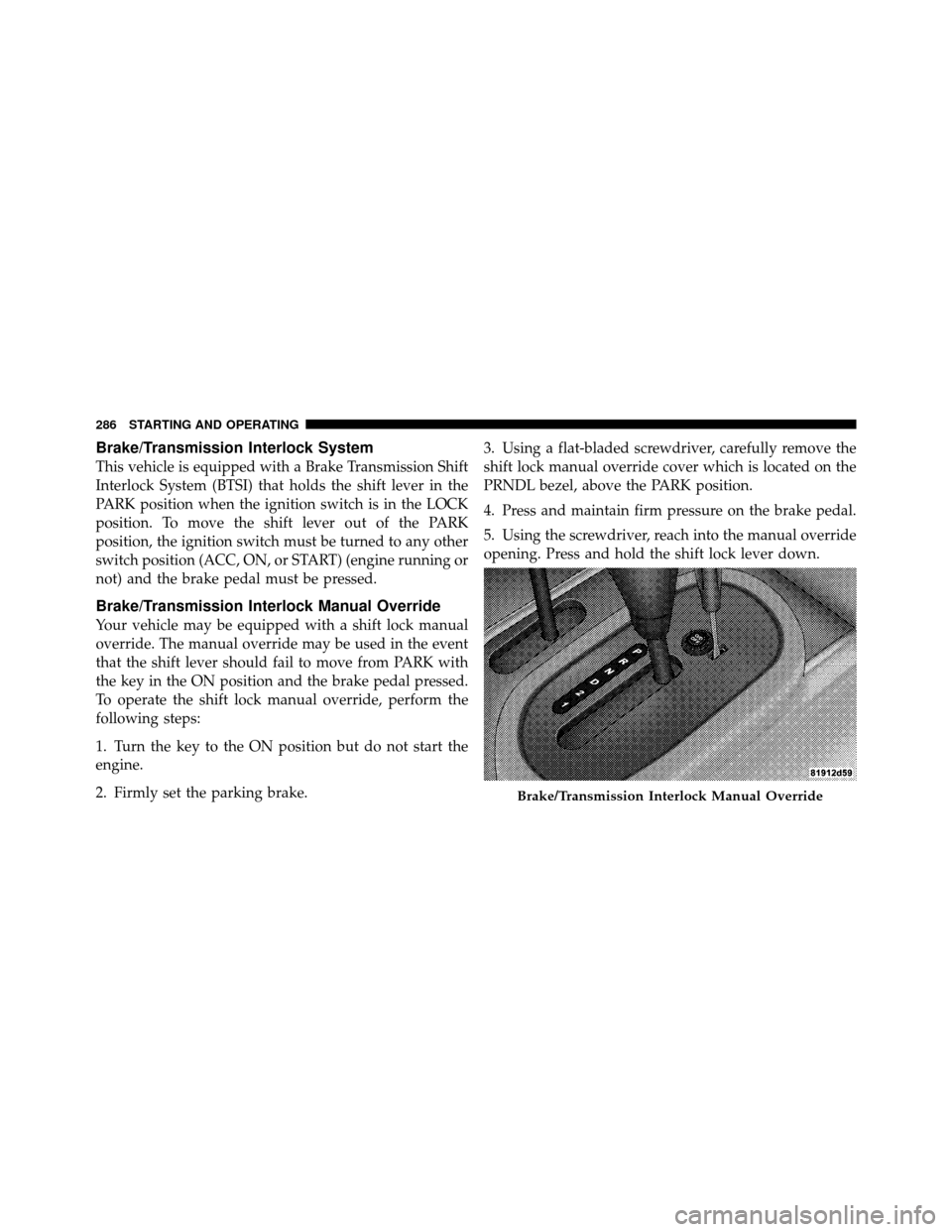
2. Firmly set the parking brake.3. Using a flat-bladed screwdriver, carefully remove the
shift lock manual override cover which is located on the
PRNDL bezel, above the PARK position.
4. Press and maintain firm pressure on the brake pedal.
5. Using the screwdriver, reach into the manual override
opening. Press and hold the shift lock lever down.
Brake/Transmission Interlock Manual Override
286 STARTING AND OPERATING
Page 294 of 502
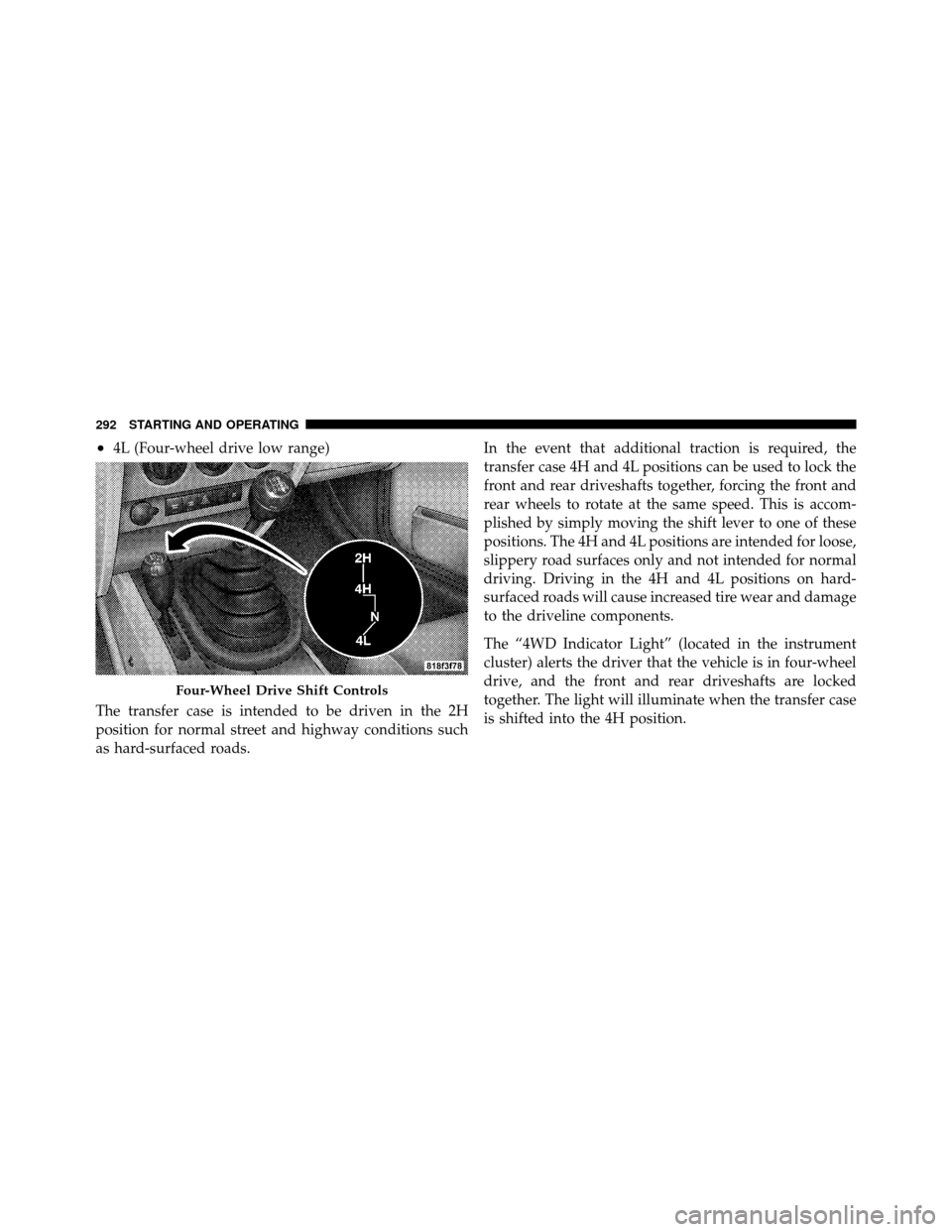
•4L (Four-wheel drive low range)
The transfer case is intended to be driven in the 2H
position for normal street and highway conditions such
as hard-surfaced roads. In the event that additional traction is required, the
transfer case 4H and 4L positions can be used to lock the
front and rear driveshafts together, forcing the front and
rear wheels to rotate at the same speed. This is accom-
plished by simply moving the shift lever to one of these
positions. The 4H and 4L positions are intended for loose,
slippery road surfaces only and not intended for normal
driving. Driving in the 4H and 4L positions on hard-
surfaced roads will cause increased tire wear and damage
to the driveline components.
The “4WD Indicator Light” (located in the instrument
cluster) alerts the driver that the vehicle is in four-wheel
drive, and the front and rear driveshafts are locked
together. The light will illuminate when the transfer case
is shifted into the 4H position.
Four-Wheel Drive Shift Controls
292 STARTING AND OPERATING
Page 295 of 502
NOTE:Do not attempt to shift when only the front or
rear wheels are spinning. The transfer case is not
equipped with a synchronizer, and the front and rear
driveshaft speeds must be equal for a shift to take place.
Shifting while only the front or rear wheels are spinning
can cause damage to the transfer case.
When operating your vehicle in 4L, the engine speed will
be approximately three times (four times for Rubicon
models) that of the 2H or 4H positions at a given road
speed. Take care not to overspeed the engine.
Proper operation of four-wheel drive vehicles depends
on tires of equal size, type, and circumference on each
wheel. Any difference will adversely affect shifting and
cause damage to the transfer case.
Because four-wheel drive provides improved traction,
there is a tendency to exceed safe turning and stopping
speeds. Do not go faster than road conditions permit.WARNING!
You or others could be injured if you leave the
vehicle unattended with the transfer case in the N
(Neutral) position without first fully engaging the
parking brake. The transfer case N (Neutral) position
disengages both the front and rear driveshaft from
the powertrain, and will allow the vehicle to move
regardless of the transmission position. The parking
brake should always be applied when the driver is
not in the vehicle.
Shift Positions
For additional information on the appropriate use of each
transfer case mode position, see the information below:
2H Position
This range is used for normal street and highway driving
on hard-surfaced roads.
5
STARTING AND OPERATING 293
Page 318 of 502
Be sure the parking brake is firmly set when parked, and
the shift lever is in the PARK position (automatic trans-
mission), or REVERSE, or first gear (manual transmis-
sion). When parking on a hill, you should apply the
parking brake before placing the shift lever in PARK;
otherwise, the load on the transmission locking mecha-
nism may make it difficult to move the shifter out of
PARK.
WARNING!
•Always fully apply the parking brake when leav-
ing your vehicle, or it may roll and cause damage
or injury. Also, be certain to leave an automatic
transmission in PARK, a manual transmission in
REVERSE or first gear. Failure to do so may allow
the vehicle to roll and cause damage or injury.(Continued)
WARNING! (Continued)
•Never leave children alone in a vehicle. Leaving
unattended children in a vehicle is dangerous for a
number of reasons. A child or others could be
seriously or fatally injured. Do not leave the key in
the ignition. A child could operate power win-
dows, other controls, or move the vehicle.
When parking on a hill, turn the front wheels toward the
curb on a downhill grade and away from the curb on an
uphill grade.
The parking brake should always be applied whenever
the driver is not in the vehicle.
ANTI-LOCK BRAKE SYSTEM
The Anti-Lock Brake System (ABS) is designed to aid the
driver in maintaining vehicle control under adverse
braking conditions. The system operates with a separate
316 STARTING AND OPERATING