ignition JEEP WRANGLER 2009 JK / 3.G Repair Manual
[x] Cancel search | Manufacturer: JEEP, Model Year: 2009, Model line: WRANGLER, Model: JEEP WRANGLER 2009 JK / 3.GPages: 502, PDF Size: 14.47 MB
Page 299 of 502
To activate the system, press the bottom of the AXLE
LOCK switch once to lock the rear axle only (the “Rear
Axle Lock Indicator Light” will illuminate), press the
bottom of the switch again to lock the front axle (the
“Front Axle Lock Indicator Light” will illuminate). When
the rear axle is locked, pressing the switch again will lock
or unlock the front axle.
NOTE:The indicator lights will flash until the axles are
fully locked or unlocked.
To unlock the axles, press the top of the AXLE LOCK
switch.
Axle lock will disengage if the vehicle is taken out of 4L
(Low) range, or the ignition switch is turned to the OFF
position.REAR AXLE LOCK (FOUR-WHEEL DRIVE
NON-RUBICON MODELS) — IF EQUIPPED
The REAR AXLE LOCK switch is located on the lower
switch bank (below the climate controls).
This feature will only activate when the following con-
ditions are met:
•Key in ignition, vehicle in 4L (Low) range.
•Vehicle speed should be 10 mph (16 km/h) or less.
To activate the system, press the REAR AXLE LOCK
switch down to lock the rear axle (the “Rear Axle Lock
Indicator Light” will illuminate); press the switch up to
unlock the rear axle.
NOTE: The indicator lights will flash until the axle is
fully locked or unlocked.5
STARTING AND OPERATING 297
Page 300 of 502
The rear axle lock will disengage if the vehicle is taken
out of 4L (Low) range, or the ignition switch is turned to
the LOCK position.
ELECTRONIC SWAY BAR DISCONNECT — IF
EQUIPPED
Your vehicle may be equipped with an electronic discon-
necting stabilizer/sway bar. This system allows greater
front suspension travel in off-road situations.
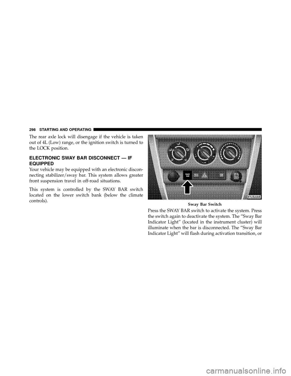
This system is controlled by the SWAY BAR switch
located on the lower switch bank (below the climate
controls).Press the SWAY BAR switch to activate the system. Press
the switch again to deactivate the system. The “Sway Bar
Indicator Light” (located in the instrument cluster) will
illuminate when the bar is disconnected. The “Sway Bar
Indicator Light” will flash during activation transition, or
Sway Bar Switch
298 STARTING AND OPERATING
Page 317 of 502
If necessary, add fluid to restore to the proper indicated
level. With a clean cloth, wipe any spilled fluid from all
surfaces. Refer to “Fluids, Lubricants, and Genuine
Parts” in Section 7 for the correct fluid type.
PARKING BRAKE
NOTE:This vehicle is not equipped with a self-
adjusting parking brake system. Refer to the “Mainte-
nance Schedule” in Section 8 for the proper maintenance
intervals.
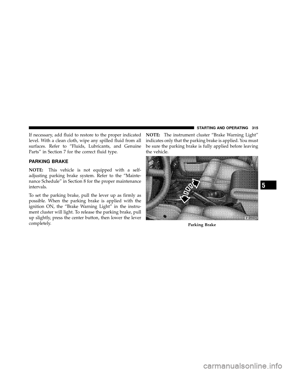
To set the parking brake, pull the lever up as firmly as
possible. When the parking brake is applied with the
ignition ON, the “Brake Warning Light” in the instru-
ment cluster will light. To release the parking brake, pull
up slightly, press the center button, then lower the lever
completely. NOTE:
The instrument cluster “Brake Warning Light”
indicates only that the parking brake is applied. You must
be sure the parking brake is fully applied before leaving
the vehicle.
Parking Brake
5
STARTING AND OPERATING 315
Page 318 of 502
Be sure the parking brake is firmly set when parked, and
the shift lever is in the PARK position (automatic trans-
mission), or REVERSE, or first gear (manual transmis-
sion). When parking on a hill, you should apply the
parking brake before placing the shift lever in PARK;
otherwise, the load on the transmission locking mecha-
nism may make it difficult to move the shifter out of
PARK.
WARNING!
•Always fully apply the parking brake when leav-
ing your vehicle, or it may roll and cause damage
or injury. Also, be certain to leave an automatic
transmission in PARK, a manual transmission in
REVERSE or first gear. Failure to do so may allow
the vehicle to roll and cause damage or injury.(Continued)
WARNING! (Continued)
•Never leave children alone in a vehicle. Leaving
unattended children in a vehicle is dangerous for a
number of reasons. A child or others could be
seriously or fatally injured. Do not leave the key in
the ignition. A child could operate power win-
dows, other controls, or move the vehicle.
When parking on a hill, turn the front wheels toward the
curb on a downhill grade and away from the curb on an
uphill grade.
The parking brake should always be applied whenever
the driver is not in the vehicle.
ANTI-LOCK BRAKE SYSTEM
The Anti-Lock Brake System (ABS) is designed to aid the
driver in maintaining vehicle control under adverse
braking conditions. The system operates with a separate
316 STARTING AND OPERATING
Page 319 of 502
computer to modulate hydraulic pressure to prevent
wheel lock-up and help avoid skidding on slippery
surfaces.
All vehicle wheels and tires must be the same size and
type, and tires must be properly inflated to produce
accurate signals for the computer.
WARNING!
Significant over or under-inflation of tires, or mixing
sizes of tires or wheels on the vehicle can lead to loss
of braking effectiveness.
The Anti-Lock Brake System conducts a low speed self-
test at about 12 mph (20 km/h). If for any reason your
foot is on the brake when the vehicle reaches 12 mph
(20 km/h), this check will be delayed until 25 mph
(40 km/h). The Anti-Lock Brake System pump motor runs during
the self-test, and during an ABS stop, to provide the
regulated hydraulic pressure. The motor pump makes a
low humming noise during operation; this is normal.
During off-road use, loss of traction can temporarily
defeat the system and cause the warning light to illumi-
nate. Turn the ignition to LOCK and ON again to restore
Anti-Lock Brake System function.WARNING!
•Pumping of the Anti-Lock Brakes will diminish
their effectiveness and may lead to an accident.
Pumping makes the stopping distance longer. Just
press firmly on your brake pedal when you need
to slow down or stop.
(Continued)
5
STARTING AND OPERATING 317
Page 326 of 502
3. With the engine running, the brake applied, and the
clutch out, rotate the steering wheel 180° counterclock-
wise from center.
4. Press the ESP OFF switch four times within twenty
seconds.
5. Rotate the steering wheel 360° clockwise (180° clock-
wise from center).
6. Cycle ignition switch OFF then ON.
7. If the sequence was completed properly, the “ESP/
TCS Indicator Light” will blink several times to confirm
HSA is off.
Steps 1-7 must be completed within 90 seconds to turn off
HSA. Repeat steps 1-7 to re-enable HSA functionality.
Electronic Roll Mitigation (ERM)
This system anticipates the potential for wheel lift by
monitoring the driver ’s steering wheel input and thespeed of the vehicle. When ERM determines that the rate
of change of the steering wheel angle and vehicle’s speed
are sufficient to potentially cause wheel lift, it applies the
appropriate brake and may reduce engine power to
lessen the chance that wheel lift will occur. ERM will only
intervene during very severe or evasive driving maneu-
vers.
Electronic Roll Mitigation (ERM) can only reduce the
chance of wheel lift occurring during severe or evasive
driving maneuvers. It cannot prevent wheel lift due to
other factors such as road conditions, leaving the road-
way or striking objects or other vehicles.
NOTE:
Anytime the ESP system is in the “Full Off”
mode, ERM is disabled. Refer to ESP (Electronic Stability
Program) for a complete explanation of the available ESP
modes.
324 STARTING AND OPERATING
Page 332 of 502
ESP and defeat the functionality of the ESP switch.
Repeating the procedure will return the system to normal
ESP operation and restore ESP switch functionality al-
lowing ESP “Partial” or “Off” modes.
WARNING!
With ESP in the permanent disable mode, enhanced
vehicle stability offered by the ESP and ERM sys-
tems is unavailable. In an emergency evasive maneu-
ver, the ESP and ERM systems will not engage to
assist in maintaining stability. This disabled mode is
intended for off-highway or off-road use only. Ve-
hicle modifications requiring the owner to configure
the vehicle in the ESP disabled mode, will seriously
affect the vehicle’s roadworthiness and safety and
may lead to loss of control and/or accident resulting
in possible serious or fatal injuries.The following procedure will disable (or re-enable) ESP
functionality in the vehicle:
1. Shift the transfer case into the 4H range position.
2. Turn the steering wheel until it is centered and the
wheels are pointed straight ahead.
3. Cycle the ignition key OFF to ON.
4. Wait approximately five seconds for the system bulb
check.
5. Turn and hold the steering wheel one-half turn to the
right (clockwise).
6. Press and hold the ESP OFF button for seven seconds.
7. Turn the steering wheel back to center, and turn and
hold an additional one-half turn to the left (counterclock-
wise).
8. Press and hold the ESP OFF button for seven seconds.
330 STARTING AND OPERATING
Page 333 of 502
9. Turn the steering wheel back to center.
10. Press and hold the ESP OFF button for seven seconds.
11. Cycle the ignition key to OFF.
After performing the ESP disable procedure correctly,
“ESP OFF” will be displayed in the odometer for approxi-
mately 12 seconds each time the ignition is moved to ON.
Repeating the ESP disable procedure will re-enable nor-
mal ESP operation.
ESP/BAS Warning Light
The malfunction indicator lamp for the ESP is
combined with the BAS indicator. The “ESP/
BAS Warning Light” in the instrument cluster
comes on when the ignition switch is turned to
the “ON” position. It should go out with the engine
running. If the “ESP/BAS Warning Light” comes on continuously
with the engine running, a malfunction has been detected
in either the ESP or the BAS system, or both. If this light
remains on after several ignition cycles, and the vehicle
has been driven several miles/kilometers at speeds
greater than 30 mph (48 km/h), see your authorized
dealer as soon as possible to have the problem diagnosed
and corrected.
NOTE:
•The “ESP/BAS Warning Light” comes on momentarily
each time the ignition switch is turned ON.
•Each time the ignition is turned ON, the ESP System
will be ON even if it was previously turned off.
•The ESP Control System will make buzzing or clicking
sounds when it is active. This is normal; the sounds
will stop when ESP becomes inactive following the
maneuver that caused the ESP activation.
5
STARTING AND OPERATING 331
Page 356 of 502
The Tire Pressure Monitor System (TPMS) consists of the
following components:
•Receiver Module
•Four Tire Pressure Monitoring Sensors
•Tire Pressure Monitoring Telltale Light
A tire pressure monitoring sensor is located in the spare
wheel if the vehicle is equipped with a matching full size
spare wheel and tire assembly. The matching full size
spare tire can be used in place of any of the four road
tires. A low spare tire will not cause the “Tire Pressure
Monitoring Telltale Light” to illuminate or the chime to
sound. The “Tire Pressure Monitoring Telltale Light” will
illuminate in the instrument cluster, and an au-
dible chime will be activated when one or more of
the four active road tire pressures are low. Should this
occur, you should stop as soon as possible, check the inflation pressure of each tire on your vehicle, and inflate
each tire to the vehicle’s recommended cold placard
pressure value. The system will automatically update
and the “Tire Pressure Monitoring Telltale Light” will
extinguish once the updated tire pressures have been
received. The vehicle may need to be driven for up to
20 minutes above 15 mph (25 km/h) to receive this
information.
The “Tire Pressure Monitoring Telltale Light” will flash
on and off for 75 seconds, and will remain on solid when
a system fault is detected. The system fault will also
sound a chime. If the ignition key is cycled, this sequence
will repeat, providing the system fault still exists. A
system fault can occur by any of the following scenarios:
1. Jamming due to electronic devices or driving next to
facilities emitting the same Radio Frequencies as the TPM
sensors.
354 STARTING AND OPERATING
Page 357 of 502
2. Installing some form of aftermarket window tinting
that affects radio wave signals.
3. Lots of snow or ice around the wheels or wheel
housings.
4. Using tire chains on the vehicle.
5. Using wheels/tires not equipped with TPM sensors.
NOTE:
•If your vehicle is equipped with a matching full-size
spare wheel and tire assembly, it has a tire pressure
monitoring sensor, and can be monitored by the Tire
Pressure Monitoring System (TPMS). In the event that
the matching full-size spare tire is swapped with a low
pressure road tire, the next ignition key cycle will still
show the “Tire Pressure Monitoring Telltale Light” to
be ON, and a chime to sound. Driving the vehicle for
up to 20 minutes above 15 mph (25 km/h) will turnOFF the “Tire Pressure Monitoring Telltale Light” as
long as none of the road tires are below the low
pressure warning threshold.
•If your vehicle is not equipped with a matching
full-size spare wheel and tire assembly, it does not
have a tire pressure monitoring sensor in the spare tire.
The TPMS will not be able to monitor the tire pressure.
If you install the spare tire in place of a road tire that
has a pressure below the low-pressure warning limit,
upon the next ignition key cycle, a chime will sound
and the “Tire Pressure Monitoring Telltale Light” will
turn ON. After driving the vehicle for up to 20 minutes
above 15 mph (25 km/h), the “Tire Pressure Monitor-
ing Telltale Light” will flash on and off for 75 seconds
and then remain on solid. For each subsequent ignition
key cycle, a chime will sound and the “Tire Pressure
Monitoring Telltale Light” will flash on and off for
75 seconds and then remain on solid. Once you repair
or replace the original road tire, and reinstall it on the
5
STARTING AND OPERATING 355