tire type JEEP WRANGLER 2010 JK / 3.G Owners Manual
[x] Cancel search | Manufacturer: JEEP, Model Year: 2010, Model line: WRANGLER, Model: JEEP WRANGLER 2010 JK / 3.GPages: 554, PDF Size: 10.76 MB
Page 47 of 554
Automatic Locking Retractors (ALR) Mode — If
Equipped
In this mode, the shoulder belt is automatically pre-
locked. The belt will still retract to remove any slack in
the shoulder belt. The Automatic Locking Mode is avail-
able on all passenger-seating positions with a combina-
tion lap/shoulder belt.
When To Use The Automatic Locking Mode
Use the Automatic Locking Mode anytime a child safety
seat is installed in a seating position that has a belt with
this feature. Children 12 years old and under should
always be properly restrained in the rear seat.
How To Engage The Automatic Locking Mode
1. Buckle the combination lap and shoulder belt.
2. Grasp the shoulder portion and pull downward until
the entire belt is extracted.3. Allow the belt to retract. As the belt retracts, you will
hear a clicking sound. This indicates the safety belt is
now in the Automatic Locking Mode.
How To Disengage The Automatic Locking Mode
Unbuckle the combination lap/shoulder belt and allow it
to retract completely to disengage the Automatic Locking
Mode and activate the vehicle sensitive (emergency)
locking mode.
Seat Belts In Passenger Seating Positions
The seat belts in the passenger seating positions are
equipped with Automatic Locking Retractors (ALR)
which are used to secure a child restraint system. For
additional information refer to “Installing Child Re-
straints Using the Vehicle Seat Belt” under the “Child
Restraints” section. The chart below defines the type of
feature for each seating position.
46 THINGS TO KNOW BEFORE STARTING YOUR VEHICLE
Page 65 of 554
Here are some tips for getting the most out of your child
restraint:
•Before buying any restraint system, make sure that it
has a label certifying that it meets all applicable Safety
Standards. The manufacturer also recommends that
you try a child restraint in the vehicle seats where you
will use it before you buy it.
•The restraint must be appropriate for your child’s
weight and height. Check the label on the restraint for
weight and height limits.
•Carefully follow the instructions that come with the
restraint. If you install the restraint improperly, it may
not work when you need it.
•The seat belts in the passenger seating positions are
equipped with either an Automatic Locking Retractor
(ALR) or a cinching latch plate or both. Both types of
seat belts are designed to keep the lap portion of the
seat belt tight around the child restraint so that it is notnecessary to use a locking clip. The ALR will make a
ratcheting noise if you extract the entire belt from the
retractor and then allow the belt to retract into the
retractor. For additional information on ALR, refer to
“Automatic Locking Mode”.
•In the rear seat, you may have trouble tightening the
lap/shoulder belt on the child restraint because the
buckle or latch plate is too close to the belt path
opening on the restraint. Disconnect the latch plate
from the buckle and twist the short buckle-end belt
several times to shorten it. Insert the latch plate into
the buckle with the release button facing out.
•If the belt still cannot be tightened, or if pulling and
pushing on the restraint loosens the belt, disconnect
the latch plate from the buckle, turn the buckle
around, and insert the latch plate into the buckle
again. If you still cannot make the child restraint
secure, try a different seating position.
64 THINGS TO KNOW BEFORE STARTING YOUR VEHICLE
Page 73 of 554
WARNING!
Improper installation of a child restraint to the
LATCH anchorages can lead to failure of an infant or
child restraint. The child could be badly injured or
killed. Follow the manufacturer’s directions exactly
when installing an infant or child restraint.
Installing Child Restraints Using the Vehicle Seat
Belt
The seat belts in the passenger seating positions are
equipped with an Automatic Locking Retractor to secure
a Child Restraint System (CRS). These types of seat belts
are designed to keep the lap portion of the seat belt tight
around the child restraint so that it is not necessary to use
a locking clip. The ALR will make a ratcheting noise if
you extract the entire belt from the retractor and then
allow the belt to retract into the retractor. For additional
information on ALR, refer to “Automatic Locking Mode”description under “Seat Belts in Passenger Seating Posi-
tions” section. The chart below defines the seating posi-
tions with an Automatic Locking Retractor (ALR) or a
cinching latch plate.
Left Center Right
CRS Lock CRS Lock CRS Lock
First Row ALR
Second Row ALR ALR ALR Third Row
Installing a Child Restraint with an ALR:
1. To install a child restraint with ALR, first, pull enough
of the seat belt webbing from the retractor to route it
through the belt path of the child restraint. Slide the latch
plate into the buckle until you hear a “click.” Next,
extract all the seat belt webbing out of the retractor and
then allow the belt to retract into the retractor. As the belt
retracts, you will hear a ratcheting sound. This indicates
the safety belt is now in the Automatic Locking mode.
72 THINGS TO KNOW BEFORE STARTING YOUR VEHICLE
Page 254 of 554
maintain correct tire pressure, even if under-inflation has
not reached the level to trigger illumination of the TPMS
low tire pressure telltale.
Your vehicle has also been equipped with a TPMS
malfunction indicator to indicate when the system is not
operating properly. The TPMS malfunction indicator is
combined with the low tire pressure telltale. When the
system detects a malfunction, the telltale will flash for
approximately one minute and then remain continuously
illuminated. This sequence will continue upon subse-
quent vehicle start-ups as long as the malfunction exists.
When the malfunction indicator is illuminated, the sys-
tem may not be able to detect or signal low tire pressure
as intended. TPMS malfunctions may occur for a variety
of reasons, including the installation of replacement or
alternate tires or wheels on the vehicle that prevent the
TPMS from functioning properly. Always check the
TPMS malfunction telltale after replacing one or moretires or wheels on your vehicle, to ensure that the
replacement or alternate tires and wheels allow the TPMS
to continue to function properly.
CAUTION!
The TPMS has been optimized for the original
equipment tires and wheels. TPMS pressures and
warning have been established for the tire size
equipped on your vehicle. Undesirable system opera-
tion or sensor damage may result when using re-
placement equipment that is not of the same size,
type, and/or style. Aftermarket wheels can cause
sensor damage. Do not use tire sealant from a can, or
balance beads if your vehicle is equipped with a
TPMS, as damage to the sensors may result.
4
UNDERSTANDING YOUR INSTRUMENT PANEL 253
Page 348 of 554
NOTE:Do not attempt to shift when only the front or
rear wheels are spinning. The transfer case is not
equipped with a synchronizer, and the front and rear
driveshaft speeds must be equal for a shift to take place.
Shifting while only the front or rear wheels are spinning
can cause damage to the transfer case.
When operating your vehicle in 4L, the engine speed will
be approximately three times (four times for Rubicon
models) that of the 2H or 4H positions at a given road
speed. Take care not to overspeed the engine.
Proper operation of four-wheel drive vehicles depends
on tires of equal size, type, and circumference on each
wheel. Any difference will adversely affect shifting and
cause damage to the transfer case.
Because four-wheel drive provides improved traction,
there is a tendency to exceed safe turning and stopping
speeds. Do not go faster than road conditions permit.WARNING!
You or others could be injured if you leave the
vehicle unattended with the transfer case in the N
(Neutral) position without first fully engaging the
parking brake. The transfer case N (Neutral) position
disengages both the front and rear driveshaft from
the powertrain, and will allow the vehicle to move
regardless of the transmission position. The parking
brake should always be applied when the driver is
not in the vehicle.
Shift Positions
For additional information on the appropriate use of each
transfer case mode position, see the information below:
2H Position
This range is used for normal street and highway driving
on hard-surfaced roads.
5
STARTING AND OPERATING 347
Page 359 of 554
previous vehicles getting stuck. As a good practice before
entering any mud hole, get out and determine how deep
it is, if there are any hidden obstacles and if the vehicle
can be safely recovered if stuck.
Sand
Soft sand is very difficult to travel through with full tire
pressure. When crossing soft, sandy spots in a trail,
maintain your vehicle’s momentum and do not stop. The
key to driving in soft sand is using the appropriate tire
pressure, accelerating slowly, avoiding abrupt maneu-
vers and maintaining the vehicle’s momentum. If you are
going to be driving on large soft sandy areas or dunes,
reduce your tire pressure to a minimum of 15 psi
(103 kPa) to allow for a greater tire surface area. Reduced
tire pressure will drastically improve your traction and
handling while driving on the soft sand, but you must
return the tires to normal air pressure before driving on
pavement or other hard surfaces. Be sure you have a way
to reinflate the tires prior to reducing the pressure.
CAUTION!
Reduced tire pressures may cause tire unseating and
total loss of air pressure. To reduce the risk of tire
unseating, while at a reduced tire pressure, reduce your
speed and avoid sharp turns or abrupt maneuvers.
Crossing Obstacles (Rocks and Other High
Points)
While driving off-road, you will encounter many types of
terrain. These varying types of terrain bring different
types of obstacles. Before proceeding, review the path
ahead to determine the correct approach and your ability
to safely recover the vehicle if something goes wrong.
Keeping a firm grip on the steering wheel, bring the
vehicle to a complete stop and then inch the vehicle
forward until it makes contact with the object. Apply the
throttle lightly while holding a light brake pressure and
ease the vehicle up and over the object.
358 STARTING AND OPERATING
Page 364 of 554
WARNING!
Driving across an incline increases the risk of a
rollover, which may result in severe injury.
If You Stall or Begin to Lose Headway
If you stall or begin to lose headway while climbing a
steep hill, allow your vehicle to come to a stop and
immediately apply the brake. Restart the engine and shift
into REVERSE. Back slowly down the hill allowing
engine braking to control the descent and apply your
brakes, if necessary, but do not allow the tires to lock.
WARNING!
If the engine stalls or you lose headway or cannot
make it to the top of a steep hill or grade, never
attempt to turn around. To do so may result in
tipping and rolling the vehicle, which may result in
severe injury. Always back carefully straight down a
hill in REVERSE gear. Never back down a hill in
NEUTRAL using only the vehicle brakes. Never
drive diagonally across a hill; always drive straight
up or down.
Driving Through Water
Extreme care should be taken crossing any type of water.
Water crossings should be avoided, if possible, and only
be attempted when necessary in a safe, responsible
manner. You should only drive through areas which are
designated and approved. You should tread lightly and
avoid damage to the environment. You should know
5
STARTING AND OPERATING 363
Page 366 of 554
muddy waters; check for hidden obstacles. Make sure
you will not be intruding on any wildlife, and you can
recover the vehicle if necessary. The key to a safe crossing
is the water depth, current and bottom conditions. On
soft bottoms, the vehicle will sink in, effectively increasing
the water level on the vehicle. Be sure to consider this when
determining the depth and the ability to safely cross.
Crossing Puddles, Pools, Flooded Areas or Other
Standing Water
Puddles, pools, flooded or other standing water areas
normally contain murky or muddy waters. These water
types normally contain hidden obstacles and make it
difficult to determine an accurate water depth, approach
angle, and bottom condition. Murky or muddy water
holes are where you want to hook up tow straps prior to
entering. This makes for a faster, cleaner and easier
vehicle recovery. If you are able to determine you can
safely cross, than proceed using the low and slow
method.
CAUTION!
Muddy waters can reduce the cooling system effec-
tiveness by depositing debris onto the radiator.
Crossing Ditches, Streams, Shallow Rivers or
Other Flowing Water
Flowing water can be extremely dangerous. Never at-
tempt to cross a fast running stream or river even in
shallow water. Fast moving water can easily push your
vehicle downstream, sweeping it out of control. Even in
very shallow water, a high current can still wash the dirt
out from around your tires putting you and your vehicle
in jeopardy. There is still a high risk of personal injury
and vehicle damage with slower water currents in depths
greater than the vehicle’s running ground clearance. You
should never attempt to cross flowing water which is
deeper than the vehicle’s running ground clearance. Even
5
STARTING AND OPERATING 365
Page 372 of 554
WARNING! (Continued)
•Always fully apply the parking brake when leav-
ing your vehicle or it may roll and cause damage or
injury. Also, be certain to leave an automatic
transmission in PARK, a manual transmission in
REVERSE or first gear. Failure to do so may cause
the vehicle to roll and cause damage or injury.
CAUTION!
If the “Brake Warning Light” remains on with the
parking brake released, a brake system malfunction
is indicated. Have the brake system serviced by an
authorized dealer immediately.
ANTI-LOCK BRAKE SYSTEM
The Anti-Lock Brake System (ABS) is designed to aid the
driver in maintaining vehicle control under adversebraking conditions. The system operates with a separate
computer to modulate hydraulic pressure to prevent
wheel lock-up and help avoid skidding on slippery
surfaces.
All vehicle wheels and tires must be the same size and
type, and tires must be properly inflated to produce
accurate signals for the computer.
WARNING!
Significant over or under-inflation of tires, or mixing
sizes of tires or wheels on the vehicle can lead to loss
of braking effectiveness.
The Anti-Lock Brake System conducts a low speed self-
test at about 12 mph (20 km/h). If for any reason your
foot is on the brake when the vehicle reaches 12 mph
(20 km/h), this check will be delayed until 25 mph
(40 km/h).
5
STARTING AND OPERATING 371
Page 400 of 554
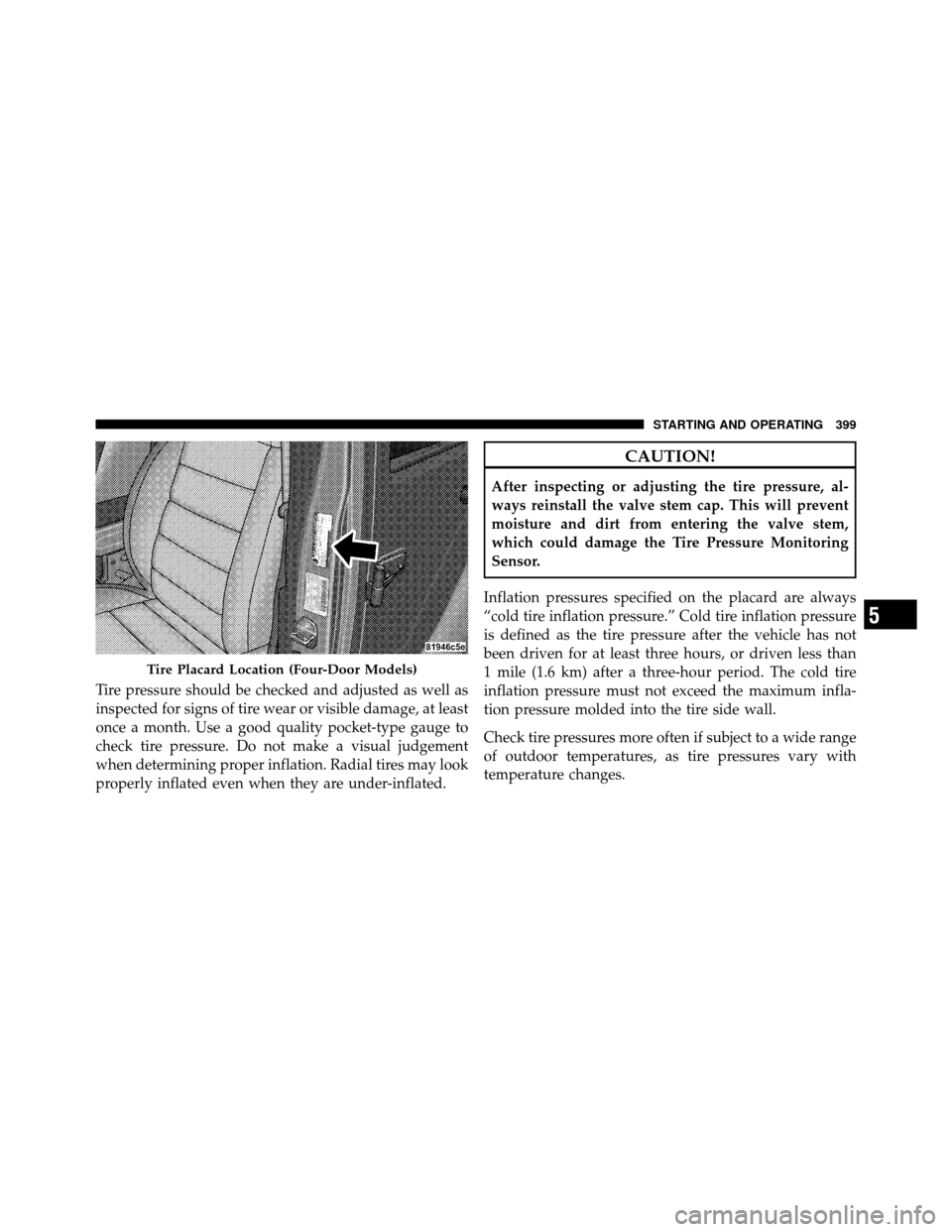
Tire pressure should be checked and adjusted as well as
inspected for signs of tire wear or visible damage, at least
once a month. Use a good quality pocket-type gauge to
check tire pressure. Do not make a visual judgement
when determining proper inflation. Radial tires may look
properly inflated even when they are under-inflated.
CAUTION!
After inspecting or adjusting the tire pressure, al-
ways reinstall the valve stem cap. This will prevent
moisture and dirt from entering the valve stem,
which could damage the Tire Pressure Monitoring
Sensor.
Inflation pressures specified on the placard are always
“cold tire inflation pressure.” Cold tire inflation pressure
is defined as the tire pressure after the vehicle has not
been driven for at least three hours, or driven less than
1 mile (1.6 km) after a three-hour period. The cold tire
inflation pressure must not exceed the maximum infla-
tion pressure molded into the tire side wall.
Check tire pressures more often if subject to a wide range
of outdoor temperatures, as tire pressures vary with
temperature changes.
Tire Placard Location (Four-Door Models)
5
STARTING AND OPERATING 399