wheel size JEEP WRANGLER 2014 JK / 3.G Owners Manual
[x] Cancel search | Manufacturer: JEEP, Model Year: 2014, Model line: WRANGLER, Model: JEEP WRANGLER 2014 JK / 3.GPages: 678, PDF Size: 4.97 MB
Page 52 of 678
OCCUPANT RESTRAINTS
Some of the most important safety features in your
vehicle are the restraint systems:
•Three-point lap and shoulder belts for the driver and
all passengers
• Advanced Front Air Bags for driver and front passen-
ger
• Supplemental Seat-Mounted Side Air Bags (SAB) — if
equipped
• An energy-absorbing steering column and steering
wheel
• Knee bolsters/blockers for front seat occupants
• Front seat belts incorporate pretensioners that may
enhance occupant protection by managing occupant
energy during an impact event •
All seat belt systems (except the driver’s) include
Automatic Locking Retractors (ALRs), which lock the
seat belt webbing into position by extending the belt
all the way out and then adjusting the belt to the
desired length to restrain a child seat or secure a large
item in a seat — if equipped
Please pay close attention to the information in this
section. It tells you how to use your restraint system
properly, to keep you and your passengers as safe as
possible.
If you will be carrying children too small for adult-sized
seat belts, the seat belts or the Lower Anchors and Tether
for CHildren (LATCH) feature also can be used to hold
infant and child restraint systems. For more information
on LATCH, refer to Lower Anchors and Tether for
CHildren (LATCH).
50 THINGS TO KNOW BEFORE STARTING YOUR VEHICLE
Page 75 of 678
are possible, based on several factors, including the
collision type and severity. The steering wheel hub trim
cover and the upper right side of the instrument panel
separate and fold out of the way as the air bags inflate to
their full size. The air bags fully inflate in about 50 to 70
milliseconds. This is about half of the time it takes to
blink your eyes. The air bags then quickly deflate while
helping to restrain the driver and front passenger.
The Advanced Front Air Bag gas is vented through the
vent holes in the sides of the air bag. In this way, the air
bags do not interfere with your control of the vehicle.
Supplemental Seat-Mounted Side Air Bags (SAB)
Inflator Units — If Equipped
The Supplemental Seat-Mounted Side Air Bags Inflator
Units (if equipped) are designed to activate only in
certain side collisions.The ORC determines if a side collision requires the side
air bags to inflate, based on the severity and type of
collision.
Based on the severity and type of collision, the side air
bag inflator on the crash side of the vehicle is triggered
releasing a quantity of non-toxic gas. The inflating SAB
exits through the seat seam into the space between the
occupant and the door. The SAB fully inflate in about 10
milliseconds. The side air bag moves at a very high speed
and with such a high force that it could injure you if you
are not seated properly, or if items are positioned in the
area where the side air bag inflates. This especially
applies to children.Front And Side Impact Sensors
In front and side impacts, impact sensors can aid the
ORC in determining appropriate response to impact
events.
2
THINGS TO KNOW BEFORE STARTING YOUR VEHICLE 73
Page 316 of 678
WARNING!(Continued)
Vehicle”. Follow the warnings under the Cooling
System Pressure Cap paragraph.
19. Cruise Indicator This indicator shows when the electronic speed
control system is turned on.
20. 4WD Indicator Light — If Equipped
This light alerts the driver that the vehicle is in
the four-wheel drive mode, and the front and
rear driveshafts are mechanically locked to-
gether forcing the front and rear wheels to
rotate at the same speed.
21. Odometer / Trip Odometer / ECO (Fuel Saver Indi-
cator) Button
Press this button to change the display from odometer to
either of the two trip odometer settings or the “ECO” display. Trip A or Trip B will appear when in the trip
odometer mode. Press and hold the button for two
seconds to reset the trip odometer to 0 miles or kilome-
ters. The odometer must be in trip mode to reset.
22. Shift Lever Indicator
The Shift Lever Indicator is self-contained within the
instrument cluster. It displays the gear position of the
automatic transmission.
23. Tire Pressure Monitoring Telltale Light
Each tire, including the spare (if provided),
should be checked monthly when cold and
inflated to the inflation pressure recommended
by the vehicle manufacturer on the vehicle
placard or tire inflation pressure label. (If your vehicle
has tires of a different size than the size indicated on the
vehicle placard or tire inflation pressure label, you should
determine the proper tire inflation pressure for those
tires.)
314 UNDERSTANDING YOUR INSTRUMENT PANEL
Page 318 of 678

CAUTION!
The TPMS has been optimized for the original
equipment tires and wheels. TPMS pressures and
warning have been established for the tire size
equipped on your vehicle. Undesirable system opera-
tion or sensor damage may result when using re-
placement equipment that is not of the same size,
type, and/or style. Aftermarket wheels can cause
sensor damage. Do not use tire sealant from a can or
balance beads if your vehicle is equipped with a
TPMS, as damage to the sensors may result.
24. Odometer / Trip Odometer Display Area
The odometer display shows the total distance the ve-
hicle has been driven. The trip odometer shows indi-
vidual trip mileage. Refer to “Odometer / Trip Odometer
/ ECO (Fuel Saver Indicator) Button” for additional
information. U.S. Federal regulations require that upon transfer of
vehicle ownership, the seller certify to the purchaser the
correct mileage that the vehicle has been driven. If your
odometer needs to be repaired or serviced, the repair
technician should leave the odometer reading the same
as it was before the repair or service. If s/he cannot do so,
then the odometer must be set at zero, and a sticker must
be placed in the door jamb stating what the mileage was
before the repair or service. It is a good idea for you to
make a record of the odometer reading before the repair/
service, so that you can be sure that it is properly reset, or
that the door jamb sticker is accurate if the odometer
must be reset at zero.
316 UNDERSTANDING YOUR INSTRUMENT PANEL
Page 442 of 678
rear wheels to rotate at the same speed. The 4H and 4L
positions are intended for loose, slippery road surfaces
only and not intended for normal driving. Driving in the
4H and 4L positions on hard-surfaced roads will cause
increased tire wear and damage to the driveline compo-
nents. Refer to “Shifting Procedures” in this section for
further information on shifting into 4H or 4L.
The “4WD Indicator Light” (located in the instrument
cluster) alerts the driver that the vehicle is in four-wheel
drive, and the front and rear driveshafts are locked
together. The light will illuminate when the transfer case
is shifted into the 4H position.
NOTE:Do not attempt to shift when only the front or
rear wheels are spinning. The transfer case is not
equipped with a synchronizer, and the front and rear
driveshaft speeds must be equal for a shift to take place.
Shifting while only the front or rear wheels are spinning
can cause damage to the transfer case. When operating your vehicle in 4L, the engine speed will
be approximately three times (four times for Rubicon
models) that of the 2H or 4H positions at a given road
speed. Take care not to overspeed the engine.
Proper operation of four-wheel drive vehicles depends
on tires of equal size, type, and circumference on each
wheel. Any difference will adversely affect shifting and
cause damage to the transfer case.
Because four-wheel drive provides improved traction,
there is a tendency to exceed safe turning and stopping
speeds. Do not go faster than road conditions permit.
WARNING!
You or others could be injured if you leave the
vehicle unattended with the transfer case in the
NEUTRAL (N) position without first fully engaging
(Continued)
440 STARTING AND OPERATING
Page 467 of 678
WARNING!(Continued)
•Always fully apply the parking brake when leav-
ing your vehicle or it may roll and cause damage or
injury. Also, be certain to leave an automatic trans-
mission in PARK, a manual transmission in RE-
VERSE or first gear. Failure to do so may cause the
vehicle to roll and cause damage or injury.
CAUTION!
If the “Brake Warning Light” remains on with the
parking brake released, a brake system malfunction
is indicated. Have the brake system serviced by an
authorized dealer immediately.
ANTI-LOCK BRAKE SYSTEM
The Anti-Lock Brake System (ABS) is designed to aid the
driver in maintaining vehicle control under adverse
braking conditions. The system operates with a separate
computer to modulate hydraulic pressure to prevent
wheel lock-up and help avoid skidding on slippery
surfaces.
All vehicle wheels and tires must be the same size and
type, and tires must be properly inflated to produce
accurate signals for the computer.
WARNING!
Significant over or under-inflation of tires, or mixing
sizes of tires or wheels on the vehicle can lead to loss
of braking effectiveness.
5
STARTING AND OPERATING 465
Page 503 of 678
Spare Tires — If Equipped
NOTE:For vehicles equipped with TIREFIT instead of a
spare tire, please refer to “TIREFIT KIT” in “What To Do
In Emergencies” for further information.
CAUTION!
Because of the reduced ground clearance, do not take
your vehicle through an automatic car wash with a
compact, full size or limited-use temporary spare
installed. Damage to the vehicle may result.
Spare Tire Matching Original Equipped Tire And
Wheel — If Equipped
Your vehicle may be equipped with a spare tire and
wheel equivalent in look and function to the original
equipment tire and wheel found on the front or rear axle
of your vehicle. This spare tire may be used in the tire rotation for your vehicle. If your vehicle has this option,
refer to an authorized tire dealer for the recommended
tire rotation pattern.
Compact Spare Tire — If Equipped
The compact spare is for temporary emergency use only.
You can identify if your vehicle is equipped with a
compact spare by looking at the spare tire description on
the Tire and Loading Information Placard located on the
driver ’s side door opening or on the sidewall of the tire.
Compact spare tire descriptions begin with the letter “T”
or “S” preceding the size designation. Example: T145/
80D18 103M.
T, S = Temporary Spare Tire
Since this tire has limited tread life, the original equip-
ment tire should be repaired (or replaced) and reinstalled
on your vehicle at the first opportunity.
5
STARTING AND OPERATING 501
Page 504 of 678
Do not install a wheel cover or attempt to mount a
conventional tire on the compact spare wheel, since the
wheel is designed specifically for the compact spare tire.
Do not install more than one compact spare tire and
wheel on the vehicle at any given time.
WARNING!
Compact spares are for temporary emergency use
only. With these spares, do not drive more than
50 mph (80 km/h). Temporary use spares have limited
tread life. When the tread is worn to the tread wear
indicators, the temporary use spare tire needs to be
replaced. Be sure to follow the warnings, which
apply to your spare. Failure to do so could result in
spare tire failure and loss of vehicle control.
Full Size Spare — If Equipped
The full size spare is for temporary emergency use only.
This tire may look like the originally equipped tire on thefront or rear axle of your vehicle, but it is not. This spare
tire may have limited tread life. When the tread is worn
to the tread wear indicators, the temporary use full size
spare tire needs to be replaced. Since it is not the same as
your original equipment tire, replace (or repair) the
original equipment tire and reinstall on the vehicle at the
first opportunity.
Limited-Use Spare — If Equipped
The limited-use spare tire is for temporary emergency
use only. This tire is identified by a label located on the
limited-use spare wheel. This label contains the driving
limitations for this spare. This tire may look like the
original equipped tire on the front or rear axle of your
vehicle, but it is not. Installation of this limited-use spare
tire affects vehicle handling. Since it is not the same as
your original equipment tire, replace (or repair) the
original equipment tire and reinstall on the vehicle at the
first opportunity.
502 STARTING AND OPERATING
Page 507 of 678
WARNING!
Tires and the spare tire should be replaced after six
years, regardless of the remaining tread. Failure to
follow this warning can result in sudden tire failure.
You could lose control and have a collision resulting
in serious injury or death.
Keep dismounted tires in a cool, dry place with as little
exposure to light as possible. Protect tires from contact
with oil, grease, and gasoline.
Replacement Tires
The tires on your new vehicle provide a balance of many
characteristics. They should be inspected regularly for
wear and correct cold tire inflation pressure. The manu-
facturer strongly recommends that you use tires equiva-
lent to the originals in size, quality and performance
when replacement is needed. Refer to the paragraph on
“Tread Wear Indicator.” Refer to the Tire and Loading Information placard or the Vehicle Certification Label for
the size designation of your tire. The Load Index and
Speed Symbol for your tire will be found on the original
equipment tire sidewall. See the Tire Sizing Chart ex-
ample found in the Tire Safety Information section of this
manual for more information relating to the Load Index
and Speed Symbol of a tire.
It is recommended to replace the two front tires or two
rear tires as a pair. Replacing just one tire can seriously
affect your vehicle’s handling. If you ever replace a
wheel, make sure that the wheel’s specifications match
those of the original wheels.
It is recommended you contact your authorized tire
dealer or original equipment dealer with any questions
you may have on tire specifications or capability. Failure
to use equivalent replacement tires may adversely affect
the safety, handling, and ride of your vehicle.
5
STARTING AND OPERATING 505
Page 508 of 678
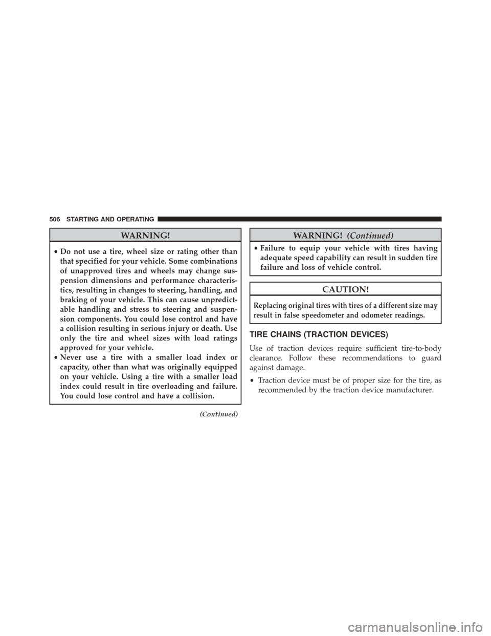
WARNING!
•Do not use a tire, wheel size or rating other than
that specified for your vehicle. Some combinations
of unapproved tires and wheels may change sus-
pension dimensions and performance characteris-
tics, resulting in changes to steering, handling, and
braking of your vehicle. This can cause unpredict-
able handling and stress to steering and suspen-
sion components. You could lose control and have
a collision resulting in serious injury or death. Use
only the tire and wheel sizes with load ratings
approved for your vehicle.
• Never use a tire with a smaller load index or
capacity, other than what was originally equipped
on your vehicle. Using a tire with a smaller load
index could result in tire overloading and failure.
You could lose control and have a collision.
(Continued)
WARNING! (Continued)
•Failure to equip your vehicle with tires having
adequate speed capability can result in sudden tire
failure and loss of vehicle control.
CAUTION!
Replacing original tires with tires of a different size may
result in false speedometer and odometer readings.
TIRE CHAINS (TRACTION DEVICES)
Use of traction devices require sufficient tire-to-body
clearance. Follow these recommendations to guard
against damage.
• Traction device must be of proper size for the tire, as
recommended by the traction device manufacturer.
506 STARTING AND OPERATING