warning light JEEP WRANGLER 2014 JK / 3.G User Guide
[x] Cancel search | Manufacturer: JEEP, Model Year: 2014, Model line: WRANGLER, Model: JEEP WRANGLER 2014 JK / 3.GPages: 148, PDF Size: 12.93 MB
Page 3 of 148
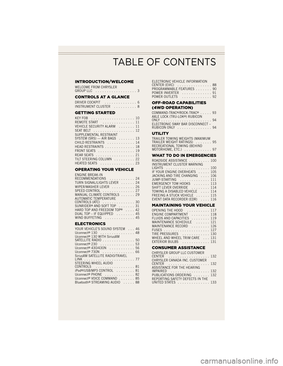
INTRODUCTION/WELCOME
WELCOME FROM CHRYSLER
GROUP LLC.................. 3
CONTROLS AT A GLANCE
DRIVER COCKPIT .............. 6
INSTRUMENT CLUSTER .......... 8
GETTING STARTED
KEYFOB ................... 10
REMOTE START.............. 11
VEHICLE SECURITY ALARM ....... 11
SEATBELT .................. 12
SUPPLEMENTAL RESTRAINT
SYSTEM (SRS) — AIR BAGS ....... 13
CHILD RESTRAINTS ............ 14
HEAD RESTRAINTS ............. 18
FRONT SEATS ................ 19
REAR SEATS ................. 21
TILT STEERING COLUMN ......... 22
HEATEDSEATS ............... 23
OPERATING YOUR VEHICLE
ENGINE BREAK-IN
RECOMMENDATIONS ........... 24
TURN SIGNAL/LIGHTS LEVER ...... 24
WIPER/WASHER LEVER .......... 26
SPEED CONTROL .............. 27
MANUAL CLIMATE CONTROLS ...... 29
AUTOMATIC TEMPERATURE
CONTROLS (ATC) .............. 30
SUNRIDER
®AND SOFT TOP ....... 31
HARD TOP AND FREEDOM TOP®.... 42
DUAL TOP – IF EQUIPPED ........ 45
WIND BUFFETING ............. 45
ELECTRONICS
YOUR VEHICLE'S SOUND SYSTEM . . . 46
Uconnect®130 ............... 48
Uconnect®130 WITH SiriusXM
SATELLITE RADIO .............. 50
Uconnect
®230 ............... 53
Uconnect®430/430N ........... 56
Uconnect®730N .............. 66
SiriusXM SATELLITE RADIO/TRAVEL
LINK ...................... 77
STEERING WHEEL AUDIO
CONTROLS ................. 81
iPod
®/USB/MP3 CONTROL ........ 81
Uconnect®PHONE ............. 82
Uconnect®VOICE COMMAND ....... 85
Bluetooth®STREAMING AUDIO ..... 88ELECTRONIC VEHICLE INFORMATION
CENTER (EVIC)
............... 88
PROGRAMMABLE FEATURES ....... 90
POWER INVERTER ............. 91
POWER OUTLETS ............. 92
OFF-ROAD CAPABILITIES
(4WD OPERATION)
COMMAND-TRAC®/ROCK-TRAC®..... 93
AXLE LOCK (TRU-LOK®) RUBICON
ONLY ...................... 94
ELECTRONIC SWAY BAR DISCONNECT –
RUBICON ONLY ............... 94
UTILITY
TRAILER TOWING WEIGHTS (MAXIMUM
TRAILER WEIGHT RATINGS) ....... 95
RECREATIONAL TOWING (BEHIND
MOTORHOME, ETC.) ............ 97
WHAT TO DO IN EMERGENCIES
ROADSIDE ASSISTANCE ......... 100
INSTRUMENT CLUSTER WARNING
LIGHTS ................... 100
IF YOUR ENGINE OVERHEATS ..... 105
JACKING AND TIRE CHANGING .... 106
JUMP-STARTING ............. 111
EMERGENCY TOW HOOKS ....... 113
SHIFT LEVER OVERRIDE ........ 114
TOWING A DISABLED VEHICLE .... 114
FREEING A STUCK VEHICLE ...... 115
EVENT DATA RECORDER (EDR) .... 116
MAINTAINING YOUR VEHICLE
OPENING THE HOOD.......... 117
ENGINE COMPARTMENT ........ 118
FLUIDS AND CAPACITIES ........ 119
MAINTENANCE SCHEDULE ...... 121
MAINTENANCE RECORD ........ 126
FUSES .................... 127
TIRE PRESSURES ............ 130
WHEEL AND WHEEL TRIM CARE . . . 131
EXTERIOR BULBS ............ 131
CONSUMER ASSISTANCE
CHRYSLER GROUP LLC CUSTOMER
CENTER.................. 132
CHRYSLER CANADA INC. CUSTOMER
CENTER .................. 132
ASSISTANCE FOR THE HEARING
IMPAIRED ................. 132
PUBLICATIONS ORDERING ....... 132
REPORTING SAFETY DEFECTS IN THE
UNITED STATES .............. 133
TABLE OF CONTENTS
Page 8 of 148
DRIVER COCKPIT
1. Electronic Vehicle Information Center (EVIC) Controls pg. 88
2. Turn Signal/Lights Lever (behind steering wheel) pg. 24
3. Electronic Vehicle Information Center (EVIC) Display
4. Instrument Cluster pg. 8
5. Wiper/Washer Lever (behind steering wheel) pg. 26
6. Audio System pg. 46
7. Power Windows
8. Climate Controls pg. 30
9. Switch Panel• Heated Seats pg. 23
• Hazard Warning Light
• Electronic Stability Control (ESC) OFF pg. 103
CONTROLS AT A GLANCE
6
Page 10 of 148
INSTRUMENT CLUSTER
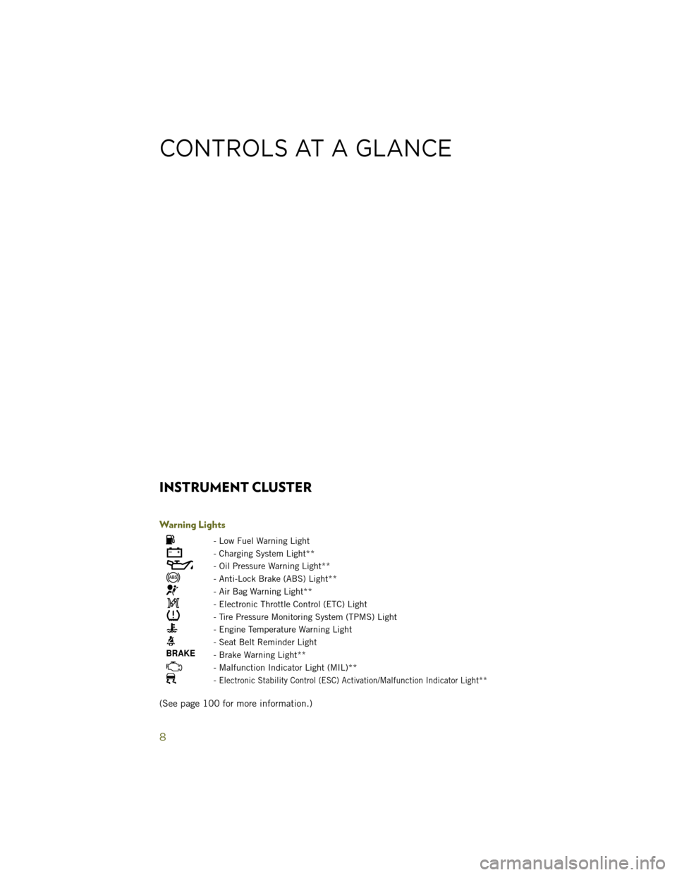
Warning Lights
- Low Fuel Warning Light
- Charging System Light**
- Oil Pressure Warning Light**
- Anti-Lock Brake (ABS) Light**
- Air Bag Warning Light**
- Electronic Throttle Control (ETC) Light
- Tire Pressure Monitoring System (TPMS) Light
- Engine Temperature Warning Light
- Seat Belt Reminder Light
- Brake Warning Light**
- Malfunction Indicator Light (MIL)**
-Electronic Stability Control (ESC) Activation/Malfunction Indicator Light**
(See page 100 for more information.)
CONTROLS AT A GLANCE
8
Page 11 of 148
Indicators
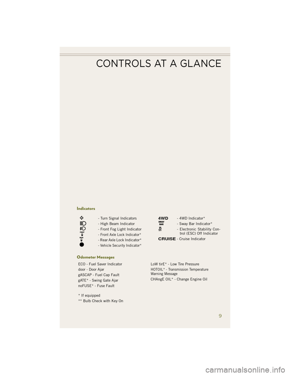
- Turn Signal Indicators
- High Beam Indicator
- Front Fog Light Indicator
-Front Axle Lock Indicator*
- Rear Axle Lock Indicator*
-Vehicle Security Indicator*
- 4WD Indicator*
- Sway Bar Indicator*
- Electronic Stability Con-trol (ESC) Off Indicator
- Cruise Indicator
Odometer Messages
ECO - Fuel Saver Indicator LoW tirE* - Low Tire Pressure
door - Door Ajar
HOTOIL* - Transmission Temperature
Warning Message
gASCAP - Fuel Cap Fault CHAngE OIL* - Change Engine Oil
gATE* - Swing Gate Ajar
noFUSE* - Fuse Fault
* If equipped
** Bulb Check with Key On
CONTROLS AT A GLANCE
9
Page 13 of 148
REMOTE START
• Press the REMOTE START buttonx2on the Key Fob twice within five seconds.
Pressing the REMOTE START button a third time shuts the engine off.
• To drive the vehicle, press the UNLOCK button, insert the key in the ignition and turn to the ON/RUN position.
• With remote start, the engine will only run for 15 minutes (timeout) unless the ignition key is placed in the ON/RUN position.
• The vehicle must be started with the key after two consecutive timeouts.
WARNING!
• Do not start or run an engine in a closed garage or confined area. Exhaust gas contains Carbon Monoxide (CO) which is odorless and colorless. Carbon
Monoxide is poisonous and can cause you or others to be severely injured or
killed when inhaled.
• Keep Key Fob transmitters away from children. Operation of the Remote Start
System, windows, door locks or other controls could cause you and others to be
severely injured or killed.
VEHICLE SECURITY ALARM
This Vehicle Security Alarm monitors the doors, liftgate, and ignition switch for
unauthorized operation.
When the alarm is activated, the interior switches for door locks are disabled. The
Vehicle Security Alarm provides both audio and visual signals repeatedly for three
minutes. If the disturbance is still present (driver's door, passenger door, other doors,
ignition) after three minutes, the parking lights and tail lights will flash for an
additional 15 minutes.
To Arm:
• Lock the door using either the power door lock switch (one door must be open) orthe LOCK button on the Remote Keyless Entry (RKE) transmitter (doors can be
open or closed), and close all doors.
The Vehicle Security Light in the instrument cluster will flash for 16 seconds. This
shows that the Vehicle Security Alarm is arming. During this period, if a door is
opened, the ignition is cycled to ON/RUN, or the power door locks are unlocked in any
manner, the Vehicle Security Alarm will automatically disarm.
NOTE:
• The Vehicle Security Alarm will not arm if you lock the doors with the manual door lock plungers.
• Once armed, the Vehicle Security Alarm disables the unlock switch on the driver door trim panel and passenger door trim panel.
GETTING STARTED
11
Page 14 of 148
To Disarm The System:
• Push the Key Fob UNLOCK button or cycle the ignition to the ON/RUN position.
The Vehicle Security Alarm is designed to protect your vehicle; however, you can create
conditions where the Vehicle Security Alarm will give you a false alarm. If one of the
previously described arming sequences has occurred, the Vehicle Security Alarm will
arm regardless of whether you are in the vehicle or not. If you remain in the vehicle and
open a door, the alarm will sound. If this occurs, disarm the Vehicle Security Alarm.
If the Vehicle Security Alarm is armed and the battery becomes disconnected the Vehicle
Security Alarm will remain armed when the battery is reconnected. The exterior lights will
flash, and the horn will sound. If this occurs, disarm the Vehicle Security Alarm.
SEAT BELT
Be sure everyone in your vehicle is in a seat and using a seat belt properly.
• Position the lap belt across your thighs, below your abdomen. To remove slack inthe lap portion, pull up a bit on the shoulder belt. To loosen the lap belt if it is too
tight, tilt the latch plate and pull on the lap belt. A snug belt reduces the risk of
sliding under the belt in a collision.
• Position the shoulder belt on your chest so that it is comfortable and not resting on your neck. The retractor will withdraw any slack in the belt.
A shoulder belt placed behind you will not protect you from injury during a collision.
You are more likely to hit your head in a collision if you do not wear your shoulder belt.
The lap and shoulder belt are meant to be used together.
A belt that is too loose will not protect you properly. In a sudden stop you could move
too far forward, increasing the possibility of injury. Wear your seat belt snugly.
A frayed or torn belt could rip apart in a collision and leave you with no protection.
Inspect the belt system periodically, checking for cuts, frays, or loose parts. Damaged
parts must be replaced immediately. Do not disassemble or modify the system. Seat
belt assemblies must be replaced after a collision if they have been damaged (bent
retractor, torn webbing, etc.).
The seat belts for both front seating positions are equipped with pretensioning
devices that are designed to remove slack from the seat belt in the event of a
collision.
A deployed pretensioner or a deployed air bag must be replaced immediately.
WARNING!
In a collision, you and your passengers can suffer much greater injuries if you are
not properly buckled up. You can strike the interior of your vehicle or other
passengers, or you can be thrown out of the vehicle. Always be sure you and others
in your vehicle are buckled up properly.
GETTING STARTED
12
Page 15 of 148
SUPPLEMENTAL RESTRAINT SYSTEM (SRS) — AIR BAGS
• This vehicle has Advanced Front Air Bags for both the driver and right frontpassenger as a supplement to the seat belt restraint system. The Advanced Front
Air Bags will not deploy in every type of collision.
• Advanced Front Air Bags are designed to provide additional protection by supplementing the seat belts in certain frontal collisions depending on several
factors, including the severity and type of collision. Advanced Front Air Bags are
not expected to reduce the risk of injury in rear, side, or rollover collisions.
• This vehicle may be equipped with Supplemental Seat-Mounted Side Air Bags to provide enhanced protection to help protect an occupant during a side impact.
• If the Air Bag Warning Light
is not on during starting, stays on, or turns on
while driving, have the vehicle serviced by an authorized service center immedi-
ately.
• Refer to the Owner's Manual on the DVD for further details regarding the Supplemental Restraint System (SRS).
WARNING!
• Relying on the air bags alone could lead to more severe injuries in a collision.
The air bags work with your seat belt to restrain you properly. In some
collisions, the air bags won't deploy at all. Always wear your seat belts even
though you have air bags.
• Being too close to the steering wheel or instrument panel during Advanced
Front Air Bag deployment could cause serious injury, including death. Air bags
need room to inflate. Sit back, comfortably extending your arms to reach the
steering wheel or instrument panel.
• Supplemental Seat-Mounted Side Air Bags need room to inflate. Do not lean
against the door or window. Sit upright in the center of the seat.
• Being too close to the Seat-Mounted Side Air Bag during deployment could
cause you to be severely injured or killed.
• Do not drive your vehicle after the air bags have deployed. If you are involved
in another collision, the air bags will not be in place to protect you.
• After any collision, the vehicle should be taken to an authorized dealer
immediately.
GETTING STARTED
13
Page 93 of 148
POWER INVERTER
• A 115 Volt, 150 Watt AC power in-verter is located on the front of the
center console.
• This outlet can power cellular phones, electronics and other low power de-
vices requiring power up to 150 Watts.
• The power inverter switch is located on the instrument panel below the cli-
mate controls. To turn on the power
outlet, press the switch once. The in-
dicator light will illuminate. Press the
switch a second time to turn the power
inverter outlet off.
NOTE:
The power inverter is designed with built-in overload protection. If the power rating
of 150 Watts is exceeded, the power inverter will automatically shut down. Once the
electrical device has been removed from the outlet, the inverter should automatically
reset. If the power rating exceeds approximately 170 Watts, the power inverter may
have to be reset manually. To reset the inverter manually, unplug the device and plug
it in again. To avoid overloading the circuit, check the power ratings on electrical
devices prior to using the inverter.
WARNING!
To Avoid Serious Injury or Death DO NOT:
• insert any objects into the receptacles
• touch with wet hands
Close the lid when not in use. If this outlet is mishandled, it may cause an electric
shock and failure.
ELECTRONICS
91
Page 102 of 148
ROADSIDE ASSISTANCE
Dial toll-free 1-800-521-2779 for U.S. Residents or 1-800-363-4869 for Canadian
Residents.
• Provide your name, vehicle identification number, license plate number, and yourlocation, including the telephone number from which you are calling.
• Briefly describe the nature of the problem and answer a few simple questions.
• You will be given the name of the service provider and an estimated time of arrival. If you feel you are in an “unsafe situation”, please let us know. With your consent,
we will contact local police or safety authorities.
INSTRUMENT CLUSTER WARNING LIGHTS
- Electronic Stability Control (ESC) Activation/Malfunction Indicator Light
• If the “ESC Activation/Malfunction Indicator Light” comes on continuously withthe engine running, a malfunction has been detected in the ESC system. If this
light remains on after several ignition cycles, and the vehicle has been driven
several miles (kilometers) at speeds greater than 30 mph (48 km/h), we recom-
mend you drive to the nearest service center and have the vehicle serviced
immediately.
• The “ESC Activation/Malfunction Indicator Light” starts to flash as soon as the tires lose traction and the ESC system becomes active. If the light begins to flash
during acceleration, ease up on the accelerator and apply as little throttle as
possible. Be sure to adapt your speed and driving to the prevailing road conditions.
The light also flashes when TCS is active. To improve the vehicle's traction when
starting off in deep snow, sand or gravel, it may be desirable to switch the ESC
system to Partial Off mode by momentarily pressing the ESC Off
switch.
- Tire Pressure Monitoring System (TPMS) Light
Each tire, including the spare (if provided), should be checked monthly when cold
and inflated to the inflation pressure recommended by the vehicle manufacturer on
the vehicle placard or tire inflation pressure label. (If your vehicle has tires of a
different size than the size indicated on the vehicle placard or tire inflation pressure
label, you should determine the proper tire inflation pressure for those tires.)
As an added safety feature, your vehicle has been equipped with a tire pressure
monitoring system (TPMS) that illuminates a low tire pressure telltale when one or
more of your tires is significantly under-inflated. Accordingly, when the low tire
pressure telltale illuminates, you should stop and check your tires as soon as
possible, and inflate them to the proper pressure. Driving on a significantly under-
inflated tire causes the tire to overheat and can lead to tire failure. Under-inflation
also reduces fuel efficiency and tire tread life, and may affect the vehicle’s handling
and stopping ability.
WHAT TO DO IN EMERGENCIES
100
Page 103 of 148
IF THE LIGHT STARTS FLASHING INDICATING A LOW TIRE PRESSURE, ADJUST THE AIR
PRESSURE IN THE LOW TIRE TO THE AIR PRESSURE SHOWN ON THE VEHICLE PLACARD OR
TIRE INFLATION PRESSURE LABEL LOCATED ON THE DRIVER'S DOOR.
NOTE:
AFTER INFLATION, THE VEHICLE MAY NEED TO BE DRIVEN FOR 20 MINUTES
BEFORE THE FLASHING LIGHT WILL TURN OFF.
Please note that the TPMS is not a substitute for proper tire maintenance, and it is
the driver’s responsibility to maintain correct tire pressure, even if under-inflation
has not reached the level to trigger illumination of the TPMS low tire pressure telltale.
Your vehicle has also been equipped with a TPMS malfunction indicator to indicate
when the system is not operating properly. The TPMS malfunction indicator is
combined with the low tire pressure telltale.
When the system detects a malfunction, the telltale will flash for approximately one
minute and then remain continuously illuminated. This sequence will continue upon
subsequent vehicle start-ups as long as the malfunction exists. When the malfunc-
tion indicator is illuminated, the system may not be able to detect or signal low tire
pressure as intended. TPMS malfunctions may occur for a variety of reasons,
including the installation of replacement or alternate tires or wheels on the vehicle
that prevent the TPMS from functioning properly. Always check the TPMS malfunc-
tion telltale after replacing one or more tires or wheels on your vehicle to ensure that
the replacement or alternate tires and wheels allow the TPMS to continue to function
properly.
NOTE:
Tire pressures change by approximately 1 psi (7 kPa) per 12° F (7° C) of air
temperature change. Keep this in mind when checking tire pressure inside a garage,
especially in the Winter. Example: If garage temperature is 68°F (20°C) and the
outside temperature is 32°F (0°C), then the cold tire inflation pressure should be
increased by 3 psi (21 kPa), which equals 1 psi (7 kPa) for every 12°F (7°C) for this
outside temperature condition.
CAUTION!
The TPMS has been optimized for the original equipment tires and wheels. TPMS
pressures and warning have been established for the tire size equipped on your
vehicle. Undesirable system operation or sensor damage may result when using
replacement equipment that is not of the same size, type, and/or style. Aftermar-
ket wheels can cause sensor damage. Do not use tire sealant from a can, or
balance beads if your vehicle is equipped with a TPMS, as damage to the sensors
may result.
WHAT TO DO IN EMERGENCIES
101