battery JEEP WRANGLER 2015 JK / 3.G User Guide
[x] Cancel search | Manufacturer: JEEP, Model Year: 2015, Model line: WRANGLER, Model: JEEP WRANGLER 2015 JK / 3.GPages: 156, PDF Size: 23.54 MB
Page 14 of 156
If the Vehicle Security Alarm is armed and the battery becomes disconnected the
Vehicle Security Alarm will remain armed when the battery is reconnected. The
exterior lights will flash, and the horn will sound. If this occurs, disarm the Vehicle
Security Alarm.
SEAT BELT SYSTEMS
Lap/Shoulder Belts
• All seating positions in your vehicle are equipped with lap/shoulder belts.
• Be sure everyone in your vehicle is in a seat and using a seat belt properly.
• Position the lap belt so that it is snug and lies low across your hips, below your
abdomen. To remove slack in the lap belt portion, pull up on the shoulder belt.
To loosen the lap belt if it is too tight, tilt the latch plate and pull on the lap belt.
A snug seat belt reduces the risk of sliding under the seat belt in a collision.
• Position the shoulder belt across the shoulder and chest with minimal, if any slack
so that it is comfortable and not resting on your neck. The retractor will withdraw
any slack in the shoulder belt.
Seat Belt Pretensioner
• The front seat belt system is equipped with pretensioning devices that are
designed to remove slack from the seat belt in the event of a collision.
• A deployed pretensioner or a deployed air bag must be replaced immediately.
WARNING!
• In a collision, you and your passengers can suffer much greater injuries if you
are not properly buckled up. You can strike the interior of your vehicle or other
passengers, or you can be thrown out of the vehicle. Always be sure you and
others in your vehicle are buckled up properly.
• A shoulder belt placed behind you will not protect you from injury during a
collision. You are more likely to hit your head in a collision if you do not wear
your shoulder belt. The lap and shoulder belt are meant to be used together.
• A seat belt that is too loose will not protect you properly. In a sudden stop, you
could move too far forward, increasing the possibility of injury. Wear your seat
belt snugly.
•A frayed or torn seat belt could rip apart in a collision and leave you with no
protection. Inspect the seat belt system periodically, checking for cuts, frays, or
loose parts. Damaged parts must be replaced immediately. Do not disassemble or
modify the system. Seat belt assemblies must be replaced after a collision.
GETTING STARTED
12
Page 87 of 156
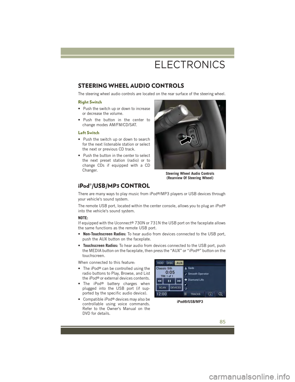
STEERING WHEEL AUDIO CONTROLS
The steering wheel audio controls are located on the rear surface of the steering wheel.
Right Switch
•Push the switch up or down to increase
or decrease the volume.
• Push the button in the center to
change modes AM/FM/CD/SAT.
Left Switch
• Push the switch up or down to search
for the next listenable station or select
the next or previous CD track.
•Push the button in the center to select
the next preset station (radio) or to
change CDs if equipped with a CD
Changer.
iPod®/USB/MP3 CONTROL
There are many ways to play music from iPod®/MP3 players or USB devices through
your vehicle's sound system.
The remote USB port, located within the center console, allows you to plug an iPod®
into the vehicle's sound system.
NOTE:
If equipped with the Uconnect®730N or 731N the USB port on the faceplate allows
the same functions as the remote USB port.
•Non-Touchscreen Radios:To hear audio from devices connected to the USB port,
push the AUX button on the faceplate.
•Touchscreen Radios:To hear audio from devices connected to the USB port, push
the MEDIA button on the faceplate, then press the “AUX” or “iPod®” button on the
touchscreen.
When connected to this feature:
• The iPod®can be controlled using the
radio buttons to Play, Browse, and List
the iPod®or external devices contents.
• The iPod®battery charges whenplugged into the USB port (if sup-ported by the specific audio device).
• Compatible iPod®devices may also becontrollable using voice commands.Refer to the Owner's Manual on theDVD for details.
Steering Wheel Audio Controls(Rearview Of Steering Wheel)
iPod®/USB/MP3
ELECTRONICS
85
Page 98 of 156
POWER OUTLETS
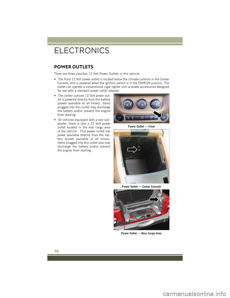
There are three possible 12 Volt Power Outlets in this vehicle.
• The front 12 Volt power outlet is located below the climate controls in the Center
Console, and is powered when the ignition switch is in the ON/RUN position. The
outlet can operate a conventional cigar lighter unit or power accessories designed
for use with a standard power outlet adapter.
• The center console 12 Volt power out-
let is powered directly from the battery
(power available at all times). Items
plugged into this outlet may discharge
the battery and/or prevent the engine
from starting.
• On vehicles equipped with a rear sub-
woofer, there is also a 12 Volt power
outlet located in the rear cargo area
of the vehicle . This power outlet has
power available directly from the bat-
tery (power available at all times).
Items plugged into this outlet also may
discharge the battery and/or prevent
the engine from starting.
Power Outlet — Front
Power Outlet — Center Console
Power Outlet — Rear Cargo Area
ELECTRONICS
96
Page 118 of 156
JUMP-STARTING
• If your vehicle has a discharged bat-
tery it can be jump-started using a set
of jumper cables and a battery in an-
other vehicle or by using a portable
battery booster pack.
• Jump-starting can be dangerous if
done improperly so please follow the
procedures in this section carefully.
NOTE:
When using a portable battery booster
pack follow the manufacturer’s operating
instructions and precautions.
Preparations For Jump-Start
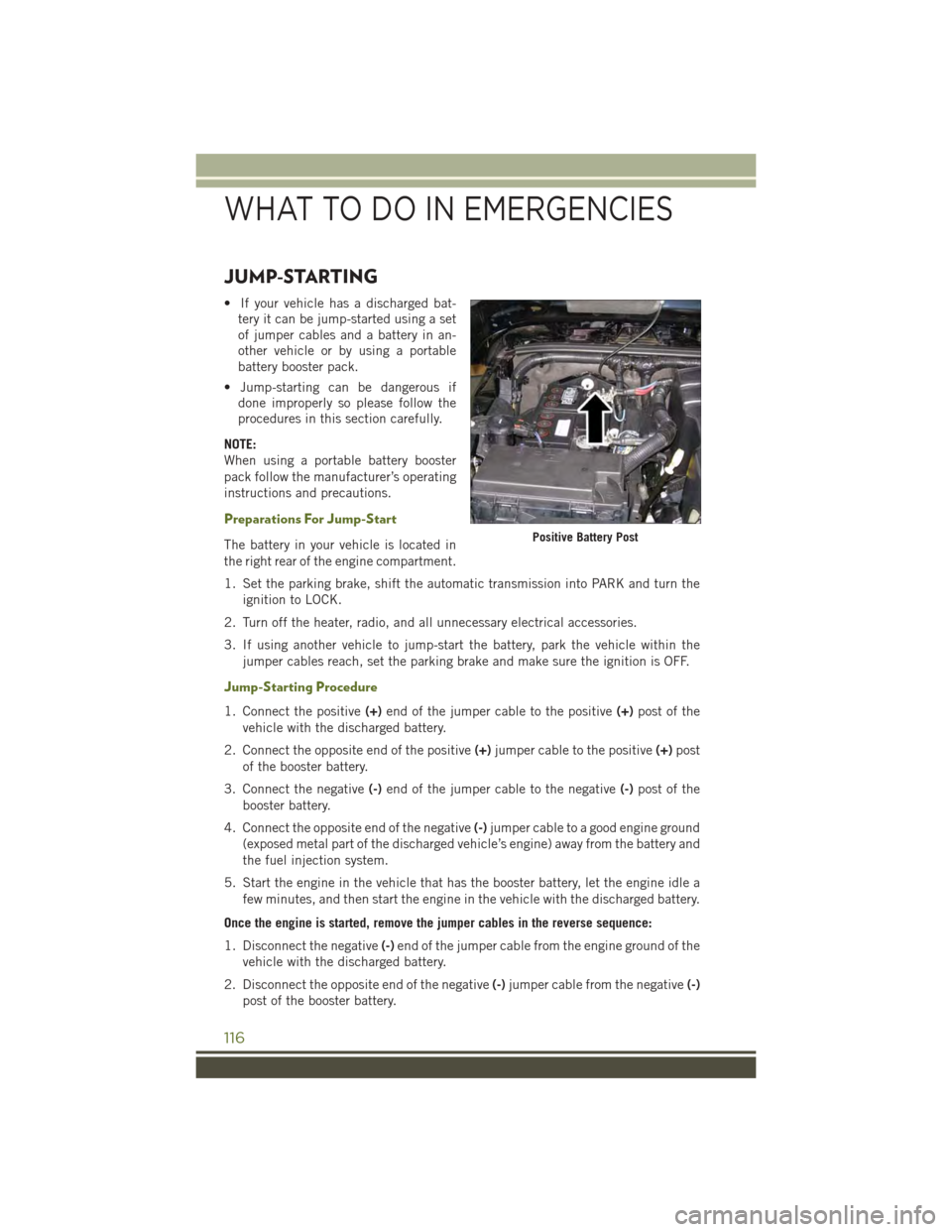
The battery in your vehicle is located in
the right rear of the engine compartment.
1. Set the parking brake, shift the automatic transmission into PARK and turn the
ignition to LOCK.
2. Turn off the heater, radio, and all unnecessary electrical accessories.
3. If using another vehicle to jump-start the battery, park the vehicle within the
jumper cables reach, set the parking brake and make sure the ignition is OFF.
Jump-Starting Procedure
1. Connect the positive(+)end of the jumper cable to the positive(+)post of the
vehicle with the discharged battery.
2. Connect the opposite end of the positive(+)jumper cable to the positive(+)post
of the booster battery.
3. Connect the negative(-)end of the jumper cable to the negative(-)post of the
booster battery.
4. Connect the opposite end of the negative(-)jumper cable to a good engine ground
(exposed metal part of the discharged vehicle’s engine) away from the battery and
the fuel injection system.
5. Start the engine in the vehicle that has the booster battery, let the engine idle a
few minutes, and then start the engine in the vehicle with the discharged battery.
Once the engine is started, remove the jumper cables in the reverse sequence:
1. Disconnect the negative(-)end of the jumper cable from the engine ground of the
vehicle with the discharged battery.
2. Disconnect the opposite end of the negative(-)jumper cable from the negative(-)
post of the booster battery.
Positive Battery Post
WHAT TO DO IN EMERGENCIES
116
Page 119 of 156
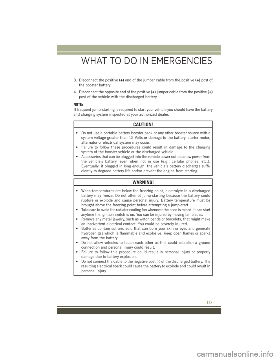
3. Disconnect the positive(+)end of the jumper cable from the positive(+)post of
the booster battery.
4. Disconnect the opposite end of the positive(+)jumper cable from the positive(+)
post of the vehicle with the discharged battery.
NOTE:
If frequent jump-starting is required to start your vehicle you should have the battery
and charging system inspected at your authorized dealer.
CAUTION!
• Do not use a portable battery booster pack or any other booster source with a
system voltage greater than 12 Volts or damage to the battery, starter motor,
alternator or electrical system may occur.
• Failure to follow these procedures could result in damage to the charging
system of the booster vehicle or the discharged vehicle.
• Accessories that can be plugged into the vehicle power outlets draw power from
the vehicle’s battery, even when not in use (e.g., cellular phones, etc.).
Eventually, if plugged in long enough, the vehicle’s battery discharges suffi-
ciently to degrade battery life and/or prevent the engine from starting.
WARNING!
• When temperatures are below the freezing point, electrolyte in a discharged
battery may freeze. Do not attempt jump-starting because the battery could
rupture or explode and cause personal injury. Battery temperature must be
brought above the freezing point before attempting a jump-start.
•Take care to avoid the radiator cooling fan whenever the hood is raised. It can start
anytime the ignition switch is on. You can be injured by moving fan blades.
• Remove any metal jewelry, such as watch bands or bracelets, that might make
an inadvertent electrical contact. You could be severely injured.
• Batteries contain sulfuric acid that can burn your skin or eyes and generate
hydrogen gas which is flammable and explosive. Keep open flames or sparks
away from the battery.
• Do not allow vehicles to touch each other as this could establish a ground
connection and personal injury could result.
• Failure to follow this procedure could result in personal injury or property
damage due to battery explosion.
• Do not connect the cable to the negative post (-) of the discharged battery. The
resulting electrical spark could cause the battery to explode and could result in
personal injury.
WHAT TO DO IN EMERGENCIES
117
Page 124 of 156
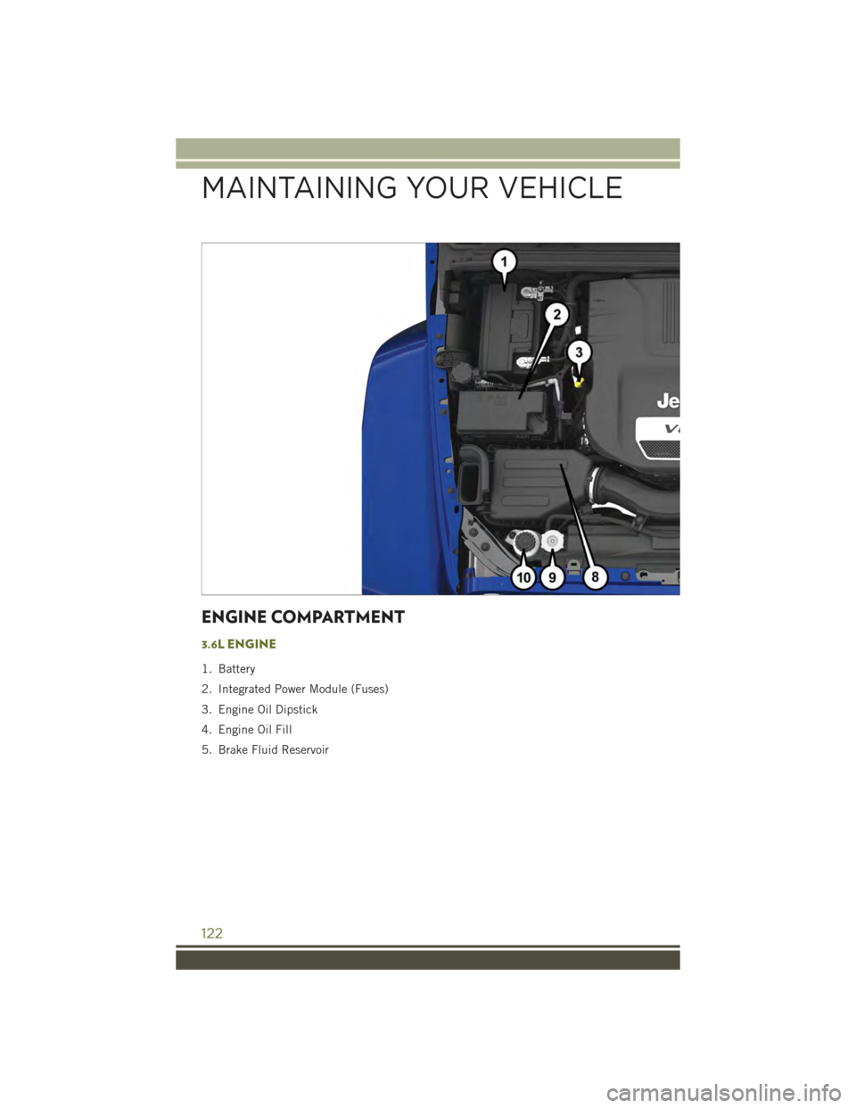
ENGINE COMPARTMENT
3.6L ENGINE
1. Battery
2. Integrated Power Module (Fuses)
3. Engine Oil Dipstick
4. Engine Oil Fill
5. Brake Fluid Reservoir
MAINTAINING YOUR VEHICLE
122
Page 129 of 156
Severe Duty All Models
Change Engine Oil at 4000 miles (6,500 km) if the vehicle is operated in a dusty and
off road environment. This type of vehicle use is considered Severe Duty
Once A Month Or Before A Long Trip:
• Check engine oil level
• Check windshield washer fluid level
• Check the tire inflation pressures and look for unusual wear or damage
• Check the fluid levels of the coolant reservoir, brake master cylinder, power
steering and automatic transmission, and fill as needed
• Check function of all interior and exterior lights
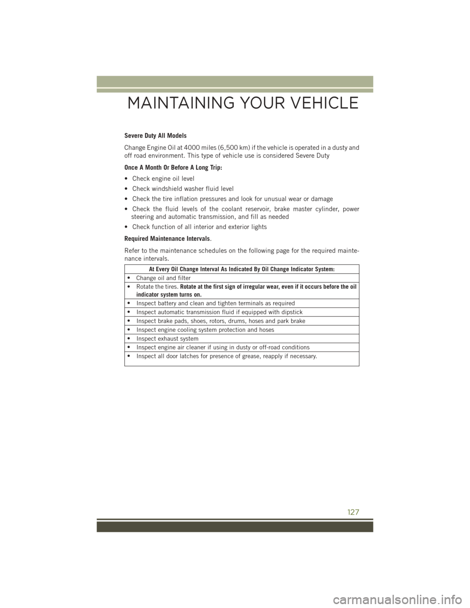
Required Maintenance Intervals.
Refer to the maintenance schedules on the following page for the required mainte-
nance intervals.
At Every Oil Change Interval As Indicated By Oil Change Indicator System:
•Change oil and filter
• Rotate the tires.Rotate at the first sign of irregular wear, even if it occurs before the oil
indicator system turns on.
•Inspect battery and clean and tighten terminals as required
•Inspect automatic transmission fluid if equipped with dipstick
•Inspect brake pads, shoes, rotors, drums, hoses and park brake
•Inspect engine cooling system protection and hoses
•Inspect exhaust system
•Inspect engine air cleaner if using in dusty or off-road conditions
•Inspect all door latches for presence of grease, reapply if necessary.
MAINTAINING YOUR VEHICLE
127
Page 133 of 156
FUSES
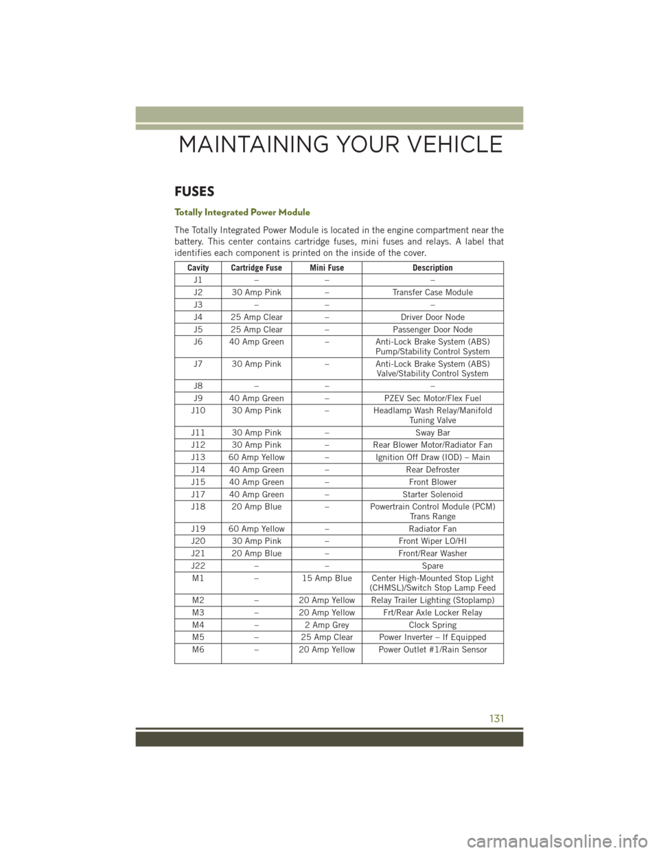
To t a l l y I n t e g r a t e d P o w e r M o d u l e
The Totally Integrated Power Module is located in the engine compartment near the
battery. This center contains cartridge fuses, mini fuses and relays. A label that
identifies each component is printed on the inside of the cover.
Cavity Cartridge Fuse Mini FuseDescription
J1–––
J2 30 Amp Pink–Tr a n s f e r C a s e M o d u l e
J3–––
J4 25 Amp Clear –Driver Door Node
J5 25 Amp Clear –Passenger Door Node
J6 40 Amp Green –Anti-Lock Brake System (ABS)Pump/Stability Control System
J7 30 Amp Pink–Anti-Lock Brake System (ABS)Valve/Stability Control System
J8–––
J9 40 Amp Green –PZEV Sec Motor/Flex Fuel
J10 30 Amp Pink–Headlamp Wash Relay/ManifoldTu n i n g V a l v e
J11 30 Amp Pink–Sway Bar
J12 30 Amp Pink–Rear Blower Motor/Radiator Fan
J13 60 Amp Yellow –Ignition Off Draw (IOD) – Main
J14 40 Amp Green –Rear Defroster
J15 40 Amp Green –Front Blower
J17 40 Amp Green –Starter Solenoid
J18 20 Amp Blue– Powertrain Control Module (PCM)Trans Range
J19 60 Amp Yellow –Radiator Fan
J20 30 Amp Pink–Front Wiper LO/HI
J21 20 Amp Blue–Front/Rear Washer
J22––Spare
M1–15 Amp Blue Center High-Mounted Stop Light(CHMSL)/Switch Stop Lamp Feed
M2– 20 Amp Yellow Relay Trailer Lighting (Stoplamp)
M3– 20 Amp Yellow Frt/Rear Axle Locker Relay
M4–2AmpGreyClock Spring
M5–25AmpClearPowerInverter–IfEquipped
M6– 20 Amp Yellow Power Outlet #1/Rain Sensor
MAINTAINING YOUR VEHICLE
131
Page 144 of 156
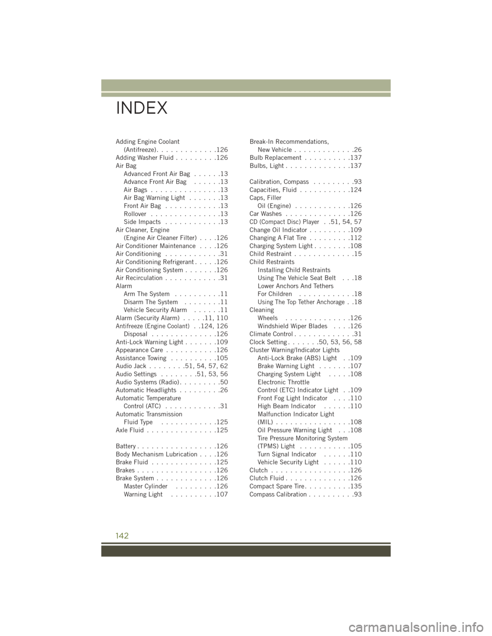
Adding Engine Coolant(Antifreeze).............126Adding Washer Fluid.........126Air BagAdvanced Front Air Bag . . . . . .13Advance Front Air Bag . . . . . .13Air Bags . . . . . . . . . . . . . . .13Air Bag Warning Light . . . . . . .13Front Air Bag . . . . . . . . . . . .13Rollover...............13Side Impacts . . . . . . . . . . . .13Air Cleaner, Engine(Engine Air Cleaner Filter)....126Air Conditioner Maintenance....126Air Conditioning............31Air Conditioning Refrigerant.....126Air Conditioning System.......126Air Recirculation............31AlarmArm The System..........11Disarm The System........11Vehicle Security Alarm......11Alarm (Security Alarm).....11,110Antifreeze (Engine Coolant)..124,126Disposal . . . . . . . . . . . . . .126Anti-Lock Warning Light.......109Appearance Care...........126Assistance Towing..........105Audio Jack........51,54,57,62Audio Settings........51,53,56Audio Systems (Radio).........50Automatic Headlights.........26Automatic TemperatureControl (ATC)............31Automatic TransmissionFluid Type . . . . . . . . . . . .125Axle Fluid . . . . . . . . . . . . . . .125
Battery.................126Body Mechanism Lubrication....126Brake Fluid . . . . . . . . . . . . . .125Brakes . . . . . . . . . . . . . . . . .126Brake System.............126Master Cylinder.........126Warning Light . . . . . . . . . .107
Break-In Recommendations,New Vehicle.............26Bulb Replacement..........137Bulbs, Light . . . . . . . . . . . . . .137
Calibration, Compass.........93Capacities, Fluid...........124Caps, FillerOil (Engine)............126Car Washes . . . . . . . . . . . . . .126CD (Compact Disc) Player..51,54,57Change Oil Indicator.........109Changing A Flat Tire . . . . . . . . .112Charging System Light........108Child Restraint.............15Child RestraintsInstalling Child RestraintsUsing The Vehicle Seat Belt . . .18Lower Anchors And TethersFor Children . . . . . . . . . . . .18Using The Top Tether Anchorage..18CleaningWheels..............126Windshield Wiper Blades....126Climate Control.............31Clock Setting.......50,53,56,58Cluster Warning/Indicator LightsAnti-Lock Brake (ABS) Light . .109Brake Warning Light.......107Charging System Light.....108Electronic ThrottleControl (ETC) Indicator Light . .109Front Fog Light Indicator....110High Beam Indicator......110Malfunction Indicator Light(MIL) . . . . . . . . . . . . . . . .108Oil Pressure Warning Light . . .108Tire Pressure Monitoring System(TPMS) Light...........105Turn Signal Indicator......110Vehicle Security Light......110Clutch . . . . . . . . . . . . . . . . .126Clutch Fluid . . . . . . . . . . . . . .126Compact Spare Tire . . . . . . . . . .135Compass Calibration..........93
INDEX
142
Page 146 of 156
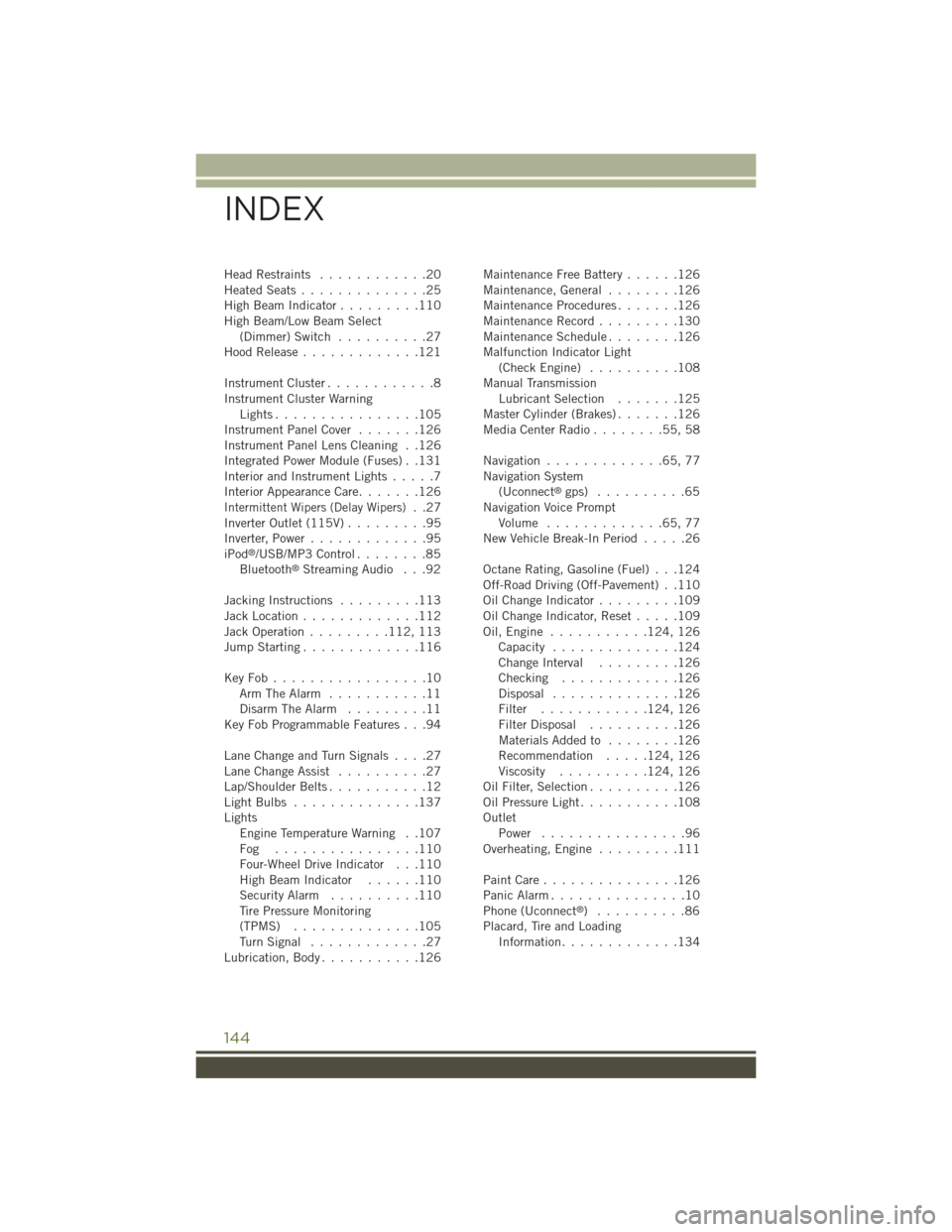
Head Restraints............20Heated Seats..............25High Beam Indicator.........110High Beam/Low Beam Select(Dimmer) Switch..........27Hood Release.............121
Instrument Cluster............8Instrument Cluster WarningLights . . . . . . . . . . . . . . . .105Instrument Panel Cover.......126Instrument Panel Lens Cleaning . .126Integrated Power Module (Fuses) . .131Interior and Instrument Lights.....7Interior Appearance Care.......126Intermittent Wipers (Delay Wipers)..27Inverter Outlet (115V).........95Inverter, Power.............95iPod®/USB/MP3 Control........85Bluetooth®Streaming Audio . . .92
Jacking Instructions.........113Jack Location.............112Jack Operation.........112, 113Jump Starting.............116
Key Fob . . . . . . . . . . . . . . . . .10Arm The Alarm...........11Disarm The Alarm.........11Key Fob Programmable Features . . .94
Lane Change and Turn Signals . . . .27Lane Change Assist..........27Lap/Shoulder Belts...........12Light Bulbs . . . . . . . . . . . . . .137LightsEngine Temperature Warning . .107Fog . . . . . . . . . . . . . . . .110Four-Wheel Drive Indicator . . .110High Beam Indicator......110Security Alarm..........110Tire Pressure Monitoring(TPMS)..............105Tu r n S i g n a l . . . . . . . . . . . . . 2 7Lubrication, Body...........126
Maintenance Free Battery......126Maintenance, General........126Maintenance Procedures.......126Maintenance Record.........130Maintenance Schedule........126Malfunction Indicator Light(Check Engine) . . . . . . . . . .108Manual TransmissionLubricant Selection.......125Master Cylinder (Brakes).......126Media Center Radio . . . . . . . .55, 58
Navigation.............65,77Navigation System(Uconnect®gps) . . . . . . . . . .65Navigation Voice PromptVolume . . . . . . . . . . . . .65, 77New Vehicle Break-In Period.....26
Octane Rating, Gasoline (Fuel) . . .124Off-Road Driving (Off-Pavement) . .110Oil Change Indicator.........109Oil Change Indicator, Reset.....109Oil, Engine . . . . . . . . . . .124, 126Capacity..............124Change Interval.........126Checking.............126Disposal..............126Filter............124, 126Filter Disposal..........126Materials Added to........126Recommendation.....124, 126Viscosity..........124, 126Oil Filter, Selection..........126Oil Pressure Light...........108OutletPower . . . . . . . . . . . . . . . .96Overheating, Engine.........111
Paint Care . . . . . . . . . . . . . . .126Panic Alarm...............10Phone (Uconnect®)..........86Placard, Tire and LoadingInformation.............134
INDEX
144