light JEEP WRANGLER 2015 JK / 3.G User Guide
[x] Cancel search | Manufacturer: JEEP, Model Year: 2015, Model line: WRANGLER, Model: JEEP WRANGLER 2015 JK / 3.GPages: 156, PDF Size: 23.54 MB
Page 3 of 156
INTRODUCTION/WELCOME
WELCOME FROM CHRYSLERGROUP LLC.................. 3
CONTROLS AT A GLANCE
DRIVER COCKPIT.............. 6INSTRUMENT CLUSTER.......... 8
GETTING STARTED
KEY FOB . . . . . . . . . . . . . . . . . . . 10REMOTE START.............. 10VEHICLE SECURITY ALARM....... 11SEAT BELT SYSTEMS........... 12SUPPLEMENTAL RESTRAINTSYSTEM (SRS) — AIR BAGS....... 13CHILD RESTRAINTS............ 15HEAD RESTRAINTS............. 20FRONT SEATS................ 21REAR SEATS................. 23TILT STEERING COLUMN......... 24HEATED SEATS . . . . . . . . . . . . . . . 25
OPERATING YOUR VEHICLE
ENGINE BREAK-INRECOMMENDATIONS........... 26TURN SIGNAL/LIGHTS LEVER...... 26WIPER/WASHER LEVER.......... 27ELECTRONIC SPEED CONTROL..... 28MANUAL CLIMATE CONTROLS...... 30AUTOMATIC TEMPERATURECONTROLS (ATC).............. 31SUNRIDER®AND SOFT TOP....... 32HARD TOP AND FREEDOM TOP®.... 43DUAL TOP – IF EQUIPPED........ 46WIND BUFFETING............. 47
ELECTRONICS
YOUR VEHICLE'S SOUND SYSTEM . . . 48Uconnect®130 . . . . . . . . . . . . . . . 50Uconnect®130 WITH SiriusXMSATELLITE RADIO.............. 52Uconnect®230 . . . . . . . . . . . . . . . 55Uconnect®430/430N........... 58Uconnect®730N.............. 69SiriusXM SATELLITE RADIO/TRAVELLINK . . . . . . . . . . . . . . . . . . . . . . 81STEERING WHEEL AUDIO CONTROLS.. 85iPod®/USB/MP3 CONTROL........ 85Uconnect®PHONE............. 86Uconnect®VOICE COMMAND....... 89
Bluetooth®STREAMING AUDIO..... 92ELECTRONIC VEHICLE INFORMATIONCENTER (EVIC)............... 92PROGRAMMABLE FEATURES....... 94POWER INVERTER............. 95POWER OUTLETS............. 96
OFF-ROAD CAPABILITIES
(4WD OPERATION)
COMMAND-TRAC®/ROCK-TRAC®..... 98AXLE LOCK (TRU-LOK®)RUBICONONLY . . . . . . . . . . . . . . . . . . . . . . 99ELECTRONIC SWAY BAR DISCONNECT –RUBICON ONLY............... 99
UTILITY
TRAILER TOWING WEIGHTS(MAXIMUM TRAILER WEIGHTRATINGS)................. 100RECREATIONAL TOWING(BEHIND MOTORHOME, ETC.)..... 102
WHAT TO DO IN EMERGENCIES
ROADSIDE ASSISTANCE......... 105INSTRUMENT CLUSTERWARNING LIGHTS............ 105INSTRUMENT CLUSTERINDICATOR LIGHTS........... 110IF YOUR ENGINE OVERHEATS..... 111JACKING AND TIRE CHANGING.... 112JUMP-STARTING............. 116EMERGENCY TOW HOOKS....... 118SHIFT LEVER OVERRIDE........ 118TOWING A DISABLED VEHICLE.... 119FREEING A STUCK VEHICLE...... 119EVENT DATA RECORDER (EDR).... 120
MAINTAINING YOUR VEHICLE
OPENING THE HOOD.......... 121ENGINE COMPARTMENT........ 122FLUID CAPACITIES............ 124FLUIDS, LUBRICANTS ANDGENUINE PARTS............. 124MAINTENANCE PROCEDURES..... 126MAINTENANCE SCHEDULE...... 126MAINTENANCE RECORD........ 130FUSES.................... 131TIRE PRESSURES............ 134SPARE TIRES — IF EQUIPPED..... 135WHEEL AND WHEEL TRIM CARE . . . 137REPLACEMENT BULBS......... 137
TABLE OF CONTENTS
Page 8 of 156
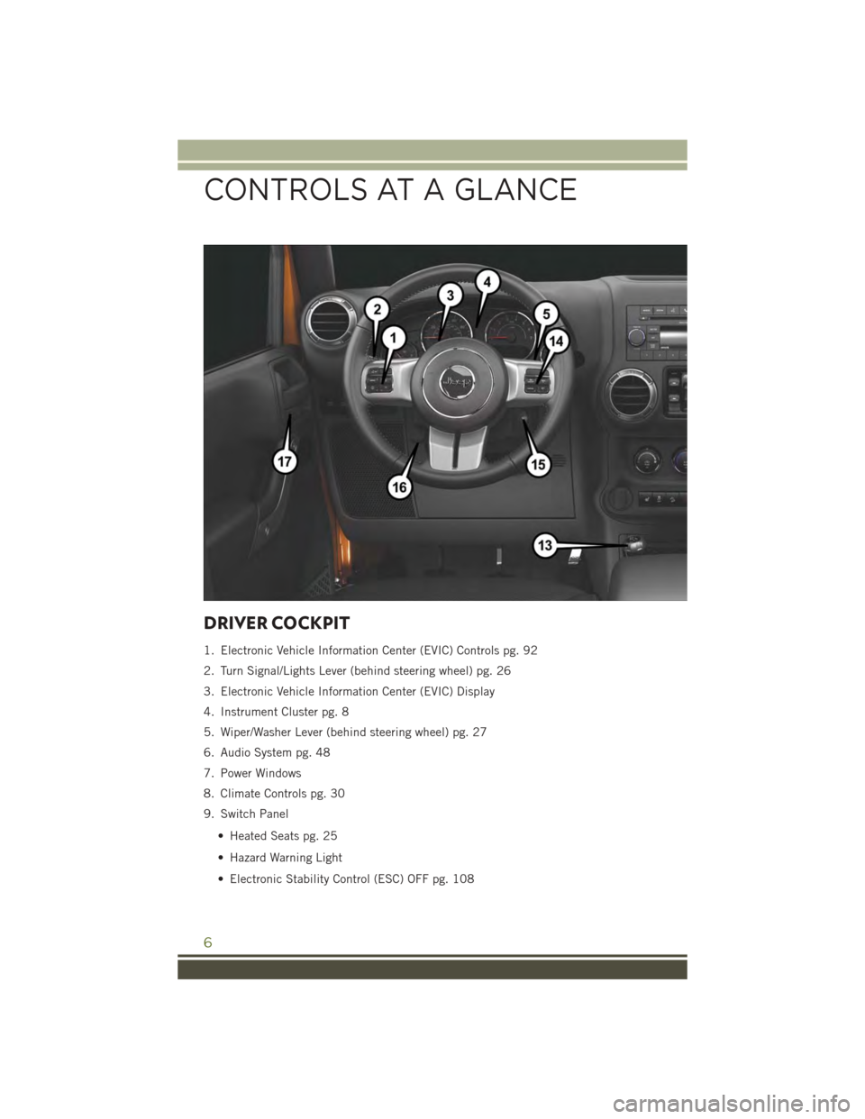
DRIVER COCKPIT
1. Electronic Vehicle Information Center (EVIC) Controls pg. 92
2. Turn Signal/Lights Lever (behind steering wheel) pg. 26
3. Electronic Vehicle Information Center (EVIC) Display
4. Instrument Cluster pg. 8
5. Wiper/Washer Lever (behind steering wheel) pg. 27
6. Audio System pg. 48
7. Power Windows
8. Climate Controls pg. 30
9. Switch Panel
• Heated Seats pg. 25
• Hazard Warning Light
• Electronic Stability Control (ESC) OFF pg. 108
CONTROLS AT A GLANCE
6
Page 10 of 156
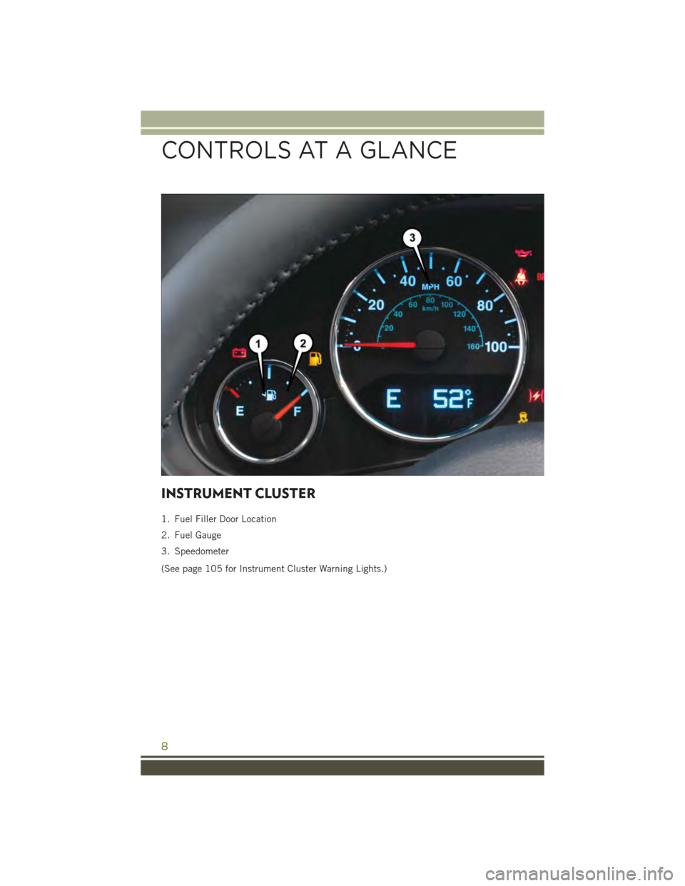
INSTRUMENT CLUSTER
1. Fuel Filler Door Location
2. Fuel Gauge
3. Speedometer
(See page 105 for Instrument Cluster Warning Lights.)
CONTROLS AT A GLANCE
8
Page 11 of 156
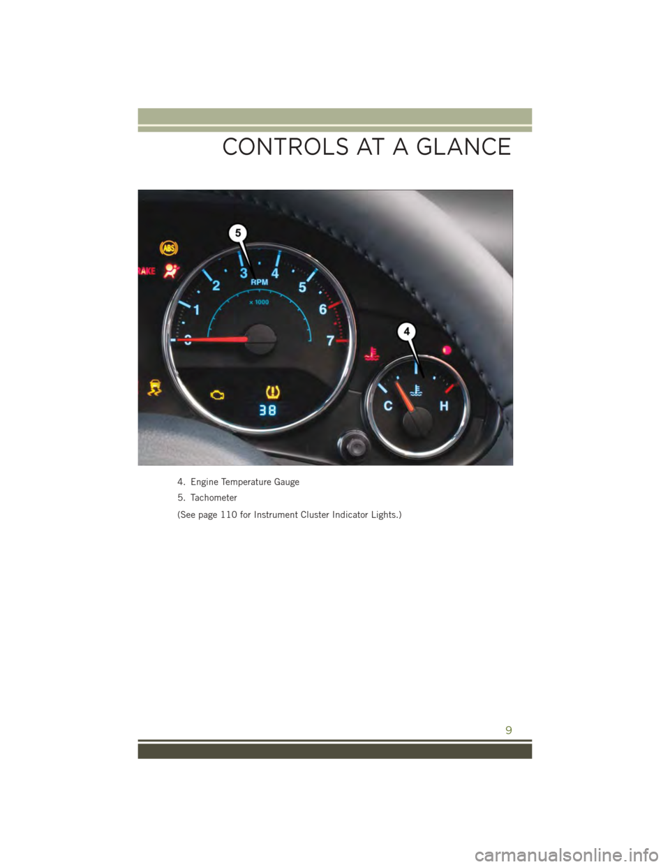
4. Engine Temperature Gauge
5. Tachometer
(See page 110 for Instrument Cluster Indicator Lights.)
CONTROLS AT A GLANCE
9
Page 13 of 156
WARNING!
• Do not start or run an engine in a closed garage or confined area. Exhaust gas
contains Carbon Monoxide (CO) which is odorless and colorless. Carbon
Monoxide is poisonous and can cause you or others to be severely injured or
killed when inhaled.
• Keep Key Fob transmitters away from children. Operation of the Remote Start
System, windows, door locks or other controls could cause you and others to be
severely injured or killed.
VEHICLE SECURITY ALARM
The Vehicle Security Alarm monitors the vehicle doors for unauthorized entry and the
Keyless Enter-N-Go™ START/STOP button for unauthorized operation. While the
Vehicle Security Alarm is armed, interior switches for door locks and decklid release
are disabled. If something triggers the alarm, the Vehicle Security Alarm will provide
the following audible and visible signals: the horn will pulse, the park lamps and/or
turn signals will flash, and the Vehicle Security Light in the instrument cluster will
flash.
To A r m :
• Lock the door using either the power door lock switch (one door must be open) or
the LOCK button on the Remote Keyless Entry (RKE) transmitter (doors can be
open or closed), and close all doors.
The Vehicle Security Light in the instrument cluster will flash for 16 seconds. This
shows that the Vehicle Security Alarm is arming. During this period, if a door is
opened, the ignition is cycled to ON/RUN, or the power door locks are unlocked in any
manner, the Vehicle Security Alarm will automatically disarm.
NOTE:
• The Vehicle Security Alarm will not arm if you lock the doors with the manual door
lock plungers.
• Once armed, the Vehicle Security Alarm disables the unlock switch on the driver
door trim panel and passenger door trim panel.
To D i s a r m T h e S y s t e m :
• Push the Key Fob UNLOCK button or cycle the ignition to the ON/RUN position.
The Vehicle Security Alarm is designed to protect your vehicle; however, you can
create conditions where the Vehicle Security Alarm will give you a false alarm. If one
of the previously described arming sequences has occurred, the Vehicle Security
Alarm will arm regardless of whether you are in the vehicle or not. If you remain in the
vehicle and open a door, the alarm will sound. If this occurs, disarm the Vehicle
Security Alarm.
GETTING STARTED
11
Page 14 of 156
If the Vehicle Security Alarm is armed and the battery becomes disconnected the
Vehicle Security Alarm will remain armed when the battery is reconnected. The
exterior lights will flash, and the horn will sound. If this occurs, disarm the Vehicle
Security Alarm.
SEAT BELT SYSTEMS
Lap/Shoulder Belts
• All seating positions in your vehicle are equipped with lap/shoulder belts.
• Be sure everyone in your vehicle is in a seat and using a seat belt properly.
• Position the lap belt so that it is snug and lies low across your hips, below your
abdomen. To remove slack in the lap belt portion, pull up on the shoulder belt.
To loosen the lap belt if it is too tight, tilt the latch plate and pull on the lap belt.
A snug seat belt reduces the risk of sliding under the seat belt in a collision.
• Position the shoulder belt across the shoulder and chest with minimal, if any slack
so that it is comfortable and not resting on your neck. The retractor will withdraw
any slack in the shoulder belt.
Seat Belt Pretensioner
• The front seat belt system is equipped with pretensioning devices that are
designed to remove slack from the seat belt in the event of a collision.
• A deployed pretensioner or a deployed air bag must be replaced immediately.
WARNING!
• In a collision, you and your passengers can suffer much greater injuries if you
are not properly buckled up. You can strike the interior of your vehicle or other
passengers, or you can be thrown out of the vehicle. Always be sure you and
others in your vehicle are buckled up properly.
• A shoulder belt placed behind you will not protect you from injury during a
collision. You are more likely to hit your head in a collision if you do not wear
your shoulder belt. The lap and shoulder belt are meant to be used together.
• A seat belt that is too loose will not protect you properly. In a sudden stop, you
could move too far forward, increasing the possibility of injury. Wear your seat
belt snugly.
•A frayed or torn seat belt could rip apart in a collision and leave you with no
protection. Inspect the seat belt system periodically, checking for cuts, frays, or
loose parts. Damaged parts must be replaced immediately. Do not disassemble or
modify the system. Seat belt assemblies must be replaced after a collision.
GETTING STARTED
12
Page 15 of 156
SUPPLEMENTAL RESTRAINT SYSTEM (SRS) —
AIR BAGS
Air Bag System Components
Your vehicle may be equipped with the following air bag system components:
• Occupant Restraint Controller (ORC)
• Air Bag Warning Light
• Steering Wheel and Column
• Instrument Panel
• Knee Impact Bolsters
• Advanced Front Air Bags
• Supplemental Side Air Bags
• Front and Side Impact Sensors
• Seat Belt Pretenioners
• Seat Belt Buckle Switch
• Seat Track Position Sensors
Advanced Front Air Bags
• This vehicle has Advanced Front Air Bags for both the driver and front passenger
as a supplement to the seat belt restraint systems. The Advanced Front Air Bags
will not deploy in every type of collision.
• Advanced Front Air Bags are designed to provide additional protection by
supplementing the seat belts. Advanced Front Air Bags are not expected to reduce
the risk of injury in rear, side, or rollover collisions.
• The Advanced Front Air Bags will not deploy in all frontal collisions, including
some that may produce substantial vehicle damage — for example, some pole
collisions, truck underrides, and angle offset collisions.
• On the other hand, depending on the type and location of impact, Advanced Front
Air Bags may deploy in crashes with little vehicle front-end damage but that
produce a severe initial deceleration.
• Because air bag sensors measure vehicle deceleration over time, vehicle speed
and damage by themselves are not good indicators of whether or not an air bag
should have deployed.
• Seat belts are necessary for your protection in all collisions, and also are needed
to help keep you in position, away from an inflating air bag.
GETTING STARTED
13
Page 16 of 156
• The air bags must be ready to inflate for your protection in a collision. The
Occupant Restraint Controller (ORC) monitors the internal circuits and intercon-
necting wiring associated with air bag system electrical components.
• The ORC turns on the Air Bag Warning Light in the instrument panel for
approximately four to eight seconds for a self-check when the ignition switch is
first turned to the ON/RUN position. After the self-check, the Air Bag Warning
Light will turn off. If the ORC detects a malfunction in any part of the system, it
turns on the Air Bag Warning Light, either momentarily or continuously. A single
chime will sound to alert you if the light comes on again after initial startup.
• The ORC monitors the readiness of the electronic parts of the air bag system
whenever the ignition switch is in the START or ON/RUN position. If the ignition
switch is in the OFF position or in the ACC position, the air bag system is not on
and the air bags will not inflate.
• If the Air Bag Warning Light in the instrument panel is not on during the four to
eight seconds when the ignition switch is first turned to the ON/RUN position,
stays on, or turns on while driving, have the vehicle serviced by an authorized
service center immediately.
NOTE:
If the speedometer, tachometer, or any engine related gauges are not working, the
Occupant Restraint Controller (ORC) may also be disabled. In this condition the air
bags may not be ready to inflate for your protection. Have an authorized dealer
service the air bag system immediately.
• After any collision, the vehicle should be taken to an authorized dealer immedi-
ately.
• Do not drive your vehicle after the air bags have deployed. If you are involved in
another collision, the air bags will not be in place to protect you.
• If it is necessary to modify the air bag system for persons with disabilities, contact
your authorized dealer.
• Refer to the Owner's Manual on the DVD for further details regarding the
Supplemental Restraint System (SRS).
GETTING STARTED
14
Page 28 of 156
ENGINE BREAK-IN RECOMMENDATIONS
A long break-in period is not required for the engine and drivetrain (transmission and
axle) in your vehicle.
Drive moderately during the first 300 miles (500 km). After the initial 60 miles (100 km),
speeds up to 50 or 55 mph (80 or 90 km/h) are desirable.
While cruising, brief full-throttle acceleration within the limits of local traffic laws
contributes to a good break-in. Wide-open throttle acceleration in low gear can be
detrimental and should be avoided.
The engine oil installed in the engine at the factory is a high-quality energy
conserving type lubricant. Oil changes should be consistent with anticipated climate
conditions under which vehicle operations will occur. For the recommended viscosity
and quality grades, refer to “Maintaining Your Vehicle.”
NOTE:
A new engine may consume some oil during its first few thousand miles (kilometers) of
operation. This should be considered a normal part of the break-in and not interpreted
as an indication of an engine problem or malfunction.
CAUTION!
Never use Non-Detergent Oil or Straight Mineral Oil in the engine or damage may
result.
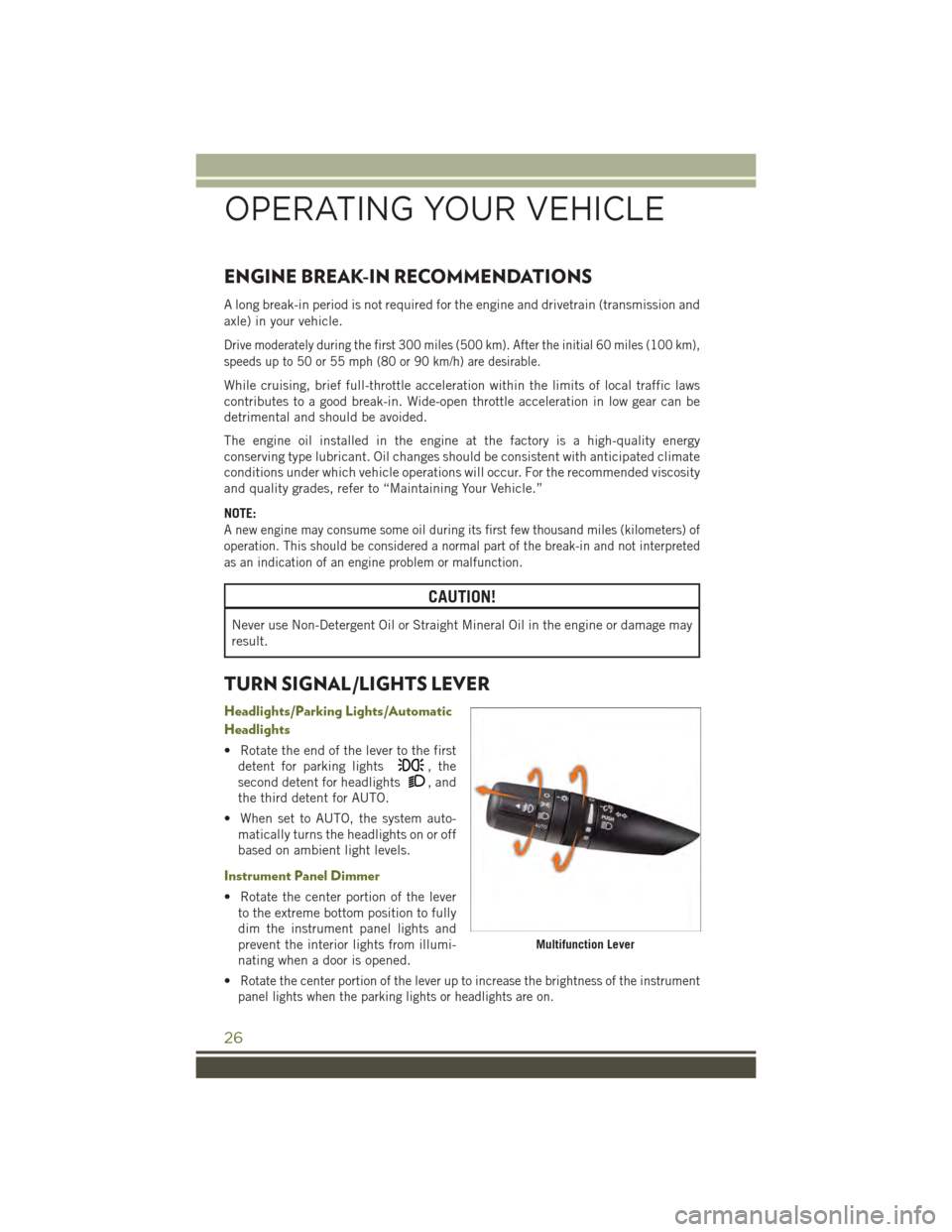
TURN SIGNAL/LIGHTS LEVER
Headlights/Parking Lights/Automatic
Headlights
• Rotate the end of the lever to the first
detent for parking lights, the
second detent for headlights, and
the third detent for AUTO.
• When set to AUTO, the system auto-
matically turns the headlights on or off
based on ambient light levels.
Instrument Panel Dimmer
• Rotate the center portion of the lever
to the extreme bottom position to fully
dim the instrument panel lights and
prevent the interior lights from illumi-
nating when a door is opened.
•Rotate the center portion of the lever up to increase the brightness of the instrument
panel lights when the parking lights or headlights are on.
Multifunction Lever
OPERATING YOUR VEHICLE
26
Page 29 of 156
•Rotate the center portion of the lever upward to the next detent position to brighten
the odometer and radio controls when the parking lights or headlights are on.
• Rotate the center portion of the lever upward to the last detent to turn on the
interior lighting.
Flash To Pass
• Pull the lever toward you to activate the high beams. The high beams will remain
on until the lever is released.
High Beam Operation
• Push the lever forward to activate the high beams.
NOTE:
For safe driving, turn off the high beams when oncoming traffic is present to prevent
headlight glare and as a courtesy to other motorists.
Fog Lights
• Turn on the parking lights or low beam headlights and pull out the end of the lever.
Turn Signals/Lane Change Assist
Tap the lever up or down once and the turn signal (right or left) will flash three times
and automatically turn off.
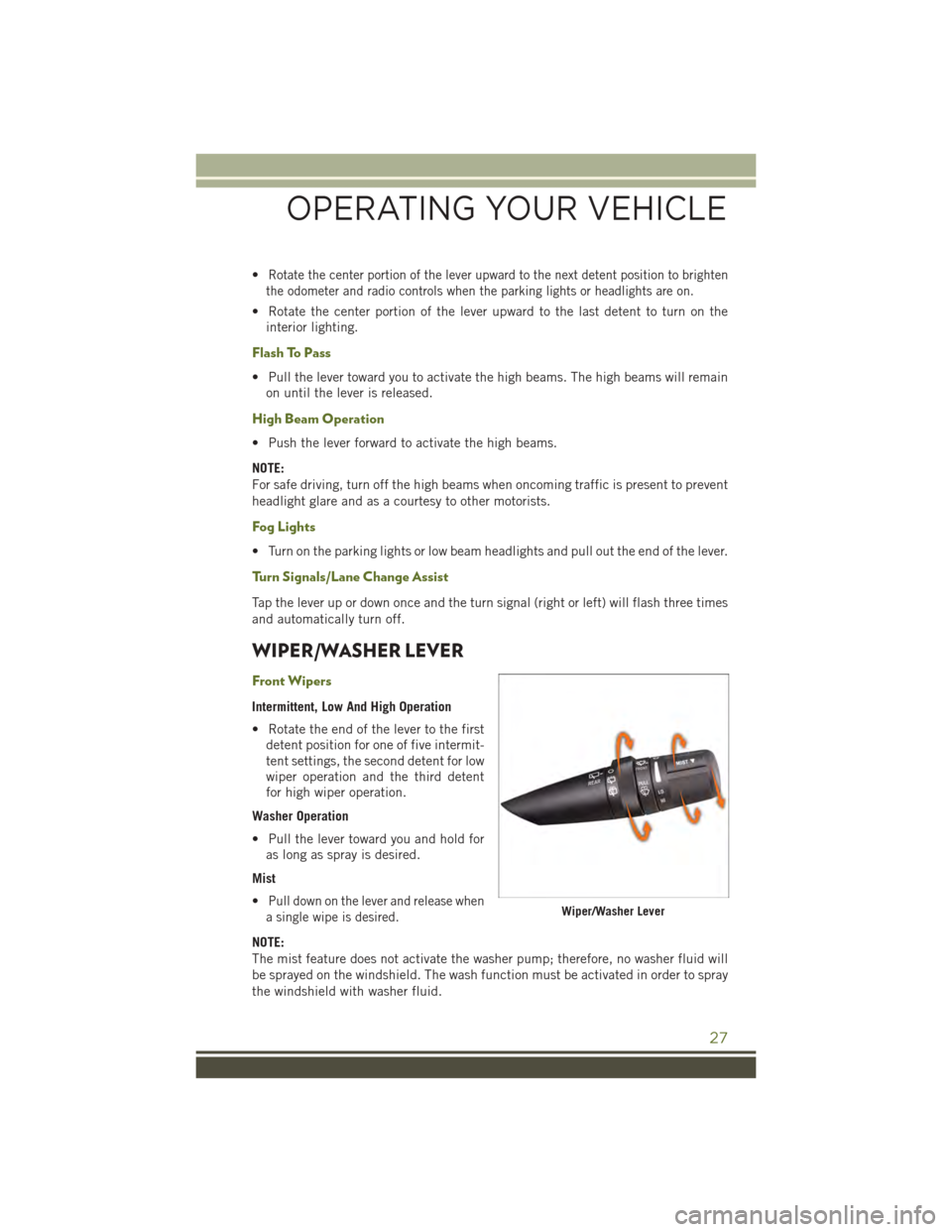
WIPER/WASHER LEVER
Front Wipers
Intermittent, Low And High Operation
• Rotate the end of the lever to the first
detent position for one of five intermit-
tent settings, the second detent for low
wiper operation and the third detent
for high wiper operation.
Washer Operation
• Pull the lever toward you and hold for
as long as spray is desired.
Mist
•Pull down on the lever and release when
a single wipe is desired.
NOTE:
The mist feature does not activate the washer pump; therefore, no washer fluid will
be sprayed on the windshield. The wash function must be activated in order to spray
the windshield with washer fluid.
Wiper/Washer Lever
OPERATING YOUR VEHICLE
27