battery JEEP WRANGLER 2016 JK / 3.G Owner's Guide
[x] Cancel search | Manufacturer: JEEP, Model Year: 2016, Model line: WRANGLER, Model: JEEP WRANGLER 2016 JK / 3.GPages: 705, PDF Size: 5.5 MB
Page 650 of 705
WARNING!(Continued)
•If a general protection fuse for safety systems (air
bag system, braking system), power unit systems
(engine system, gearbox system) or steering system
blows, contact an authorized dealer.
Totally Integrated Power Module
The Totally Integrated Power Module is located in the
engine compartment near the battery. This center con-
tains cartridge fuses, mini fuses and relays. A label that
identifies each component is printed on the inside of the
cover.
Totally Integrated Power Module
648 MAINTAINING YOUR VEHICLE
Page 656 of 705
VEHICLE STORAGE
If you are leaving your vehicle dormant for more than 21
days, you may want to take steps to protect your battery.
You may:
•Remove Cartridge fuse #J13 in the Power Distribution
Center (PDC) labeled Ignition-Off Draw (IOD) and
store it in a safe location within the PDC. •
Or, disconnect the negative cable from the battery.
• Anytime you store your vehicle, or keep it out of
service (i.e., vacation) for two weeks or more, run the
air conditioning system at idle for about five minutes
in the fresh air and high blower setting. This will
ensure adequate system lubrication to minimize the
possibility of compressor damage when the system is
started again.
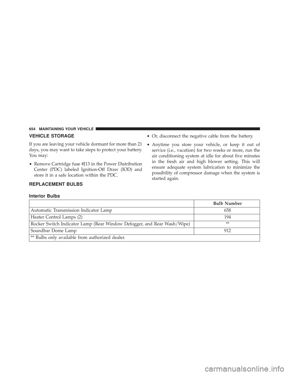
REPLACEMENT BULBS
Interior Bulbs
Bulb Number
Automatic Transmission Indicator Lamp 658
Heater Control Lamps (2) 194
Rocker Switch Indicator Lamp (Rear Window Defogger, and Rear Wash/Wipe) **
Soundbar Dome Lamp 912
** Bulbs only available from authorized dealer.
654 MAINTAINING YOUR VEHICLE
Page 668 of 705
Required Maintenance Intervals
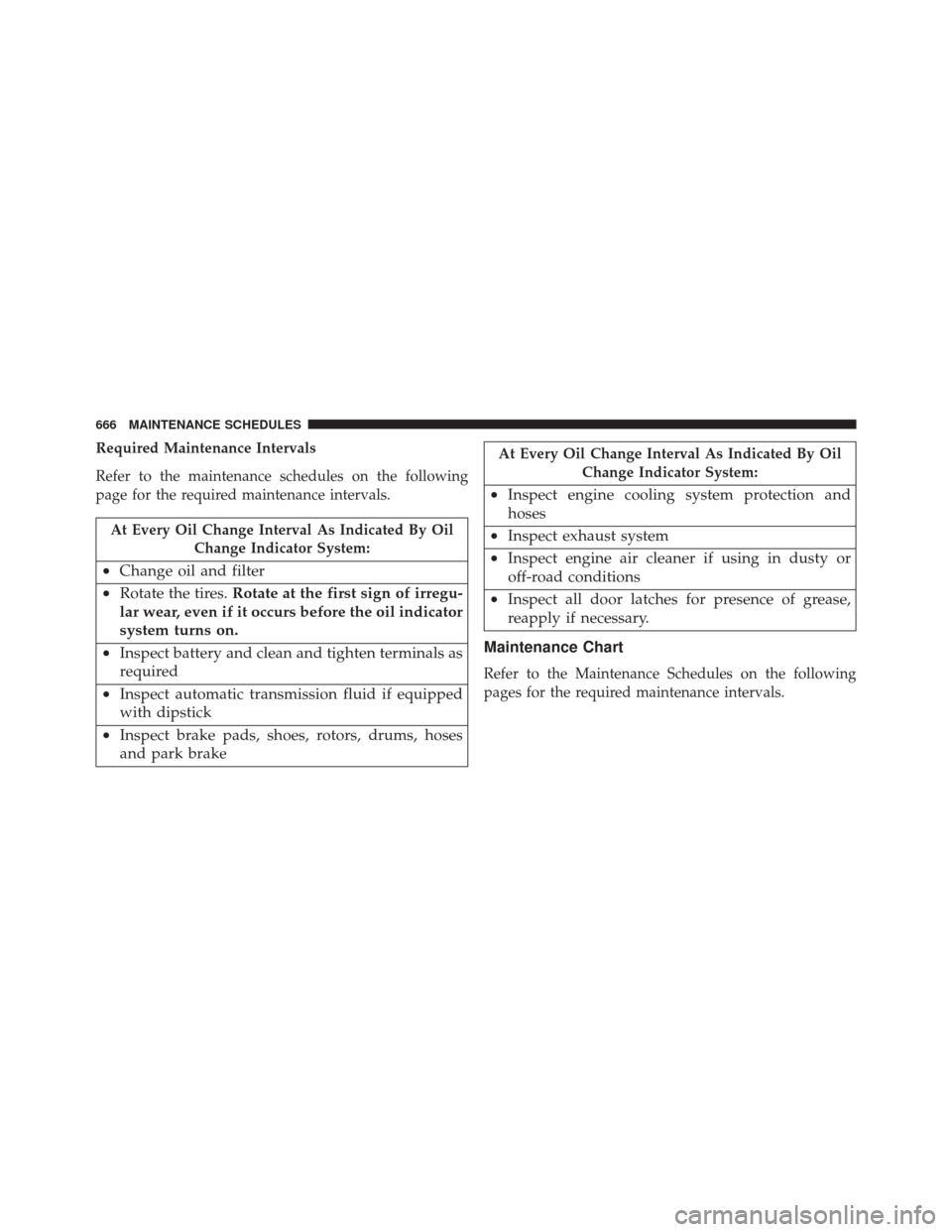
Refer to the maintenance schedules on the following
page for the required maintenance intervals.
At Every Oil Change Interval As Indicated By OilChange Indicator System:
•Change oil and filter
• Rotate the tires. Rotate at the first sign of irregu-
lar wear, even if it occurs before the oil indicator
system turns on.
• Inspect battery and clean and tighten terminals as
required
• Inspect automatic transmission fluid if equipped
with dipstick
• Inspect brake pads, shoes, rotors, drums, hoses
and park brake
At Every Oil Change Interval As Indicated By Oil
Change Indicator System:
•Inspect engine cooling system protection and
hoses
• Inspect exhaust system
• Inspect engine air cleaner if using in dusty or
off-road conditions
• Inspect all door latches for presence of grease,
reapply if necessary.
Maintenance Chart
Refer to the Maintenance Schedules on the following
pages for the required maintenance intervals.
666 MAINTENANCE SCHEDULES
Page 685 of 705
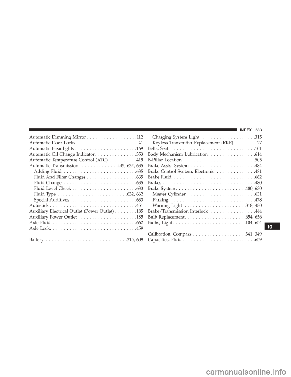
Automatic Dimming Mirror..................112
Automatic Door Locks ......................41
Automatic Headlights ..................... .169
Automatic Oil Change Indicator ...............353
Automatic Temperature Control (ATC) ..........419
Automatic Transmission ..............445, 632, 635
Adding Fluid ......................... .635
Fluid And Filter Changes ..................635
Fluid Change ......................... .635
Fluid Level Check ...................... .633
Fluid Type ........................ .632, 662
Special Additives ...................... .633
Autostick .............................. .451
Auxiliary Electrical Outlet (Power Outlet) ........185
Auxiliary Power Outlet .....................185
Axle Fluid ............................. .662
Axle Lock .............................. .459
Battery ............................ .315, 609Charging System Light
...................315
Keyless Transmitter Replacement (RKE) ........27
Belts, Seat .............................. .101
Body Mechanism Lubrication .................614
B-Pillar Location ......................... .505
Brake Assist System ...................... .484
Brake Control System, Electronic ..............481
Brake Fluid ............................ .662
Brakes ................................ .480
Brake System ........................ .480, 630
Master Cylinder ....................... .631
Parking ............................. .478
Warning Light ..................... .318, 480
Brake/Transmission Interlock .................444
Bulb Replacement ..................... .654, 656
Bulbs, Light ......................... .104, 654
Calibration, Compass .................. .341, 349
Capacities,
Fluid ......................... .659
10
INDEX 683
Page 694 of 705
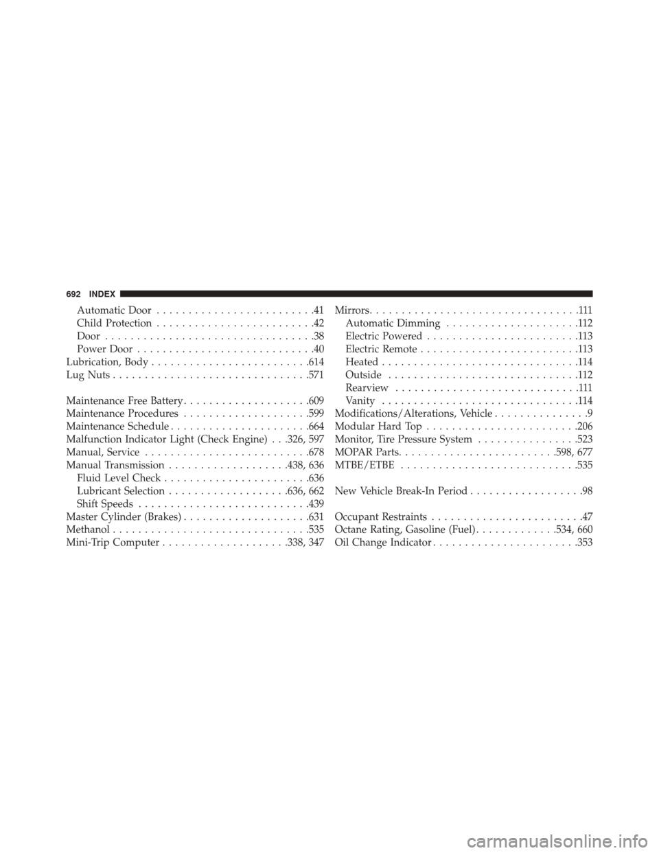
Automatic Door.........................41
Child Protection .........................42
Door .................................38
Power Door ............................40
Lubrication, Body ........................ .614
Lug Nuts .............................. .571
Maintenance Free Battery ....................609
Maintenance Procedures ....................599
Maintenance Schedule ..................... .664
Malfunction Indicator Light (Check Engine) . . .326, 597
Manual, Service ......................... .678
Manual Transmission ...................438, 636
Fluid Level Check ...................... .636
Lubricant Selection ...................636, 662
Shift Speeds .......................... .439
Master Cylinder (Brakes) ....................631
Methanol .............................. .535
Mini-Trip Computer ....................338, 347 Mirrors
.................................111
Automatic Dimming .....................112
Electric Powered ........................113
Electric Remote .........................113
Heated ...............................114
Outside ..............................112
Rearview .............................111
Vanity ...............................114
Modifications/Alterations, Vehicle ...............9
Modular Hard Top ....................... .206
Monitor, Tire Pressure System ................523
MOPAR Parts ........................ .598, 677
MTBE/ETBE ........................... .535
New Vehicle Break-In Period ..................98
Occupant Restraints ........................47
Octane Rating, Gasoline (Fuel) .............534, 660
Oil Change Indicator ...................... .353
692 INDEX
Page 701 of 705
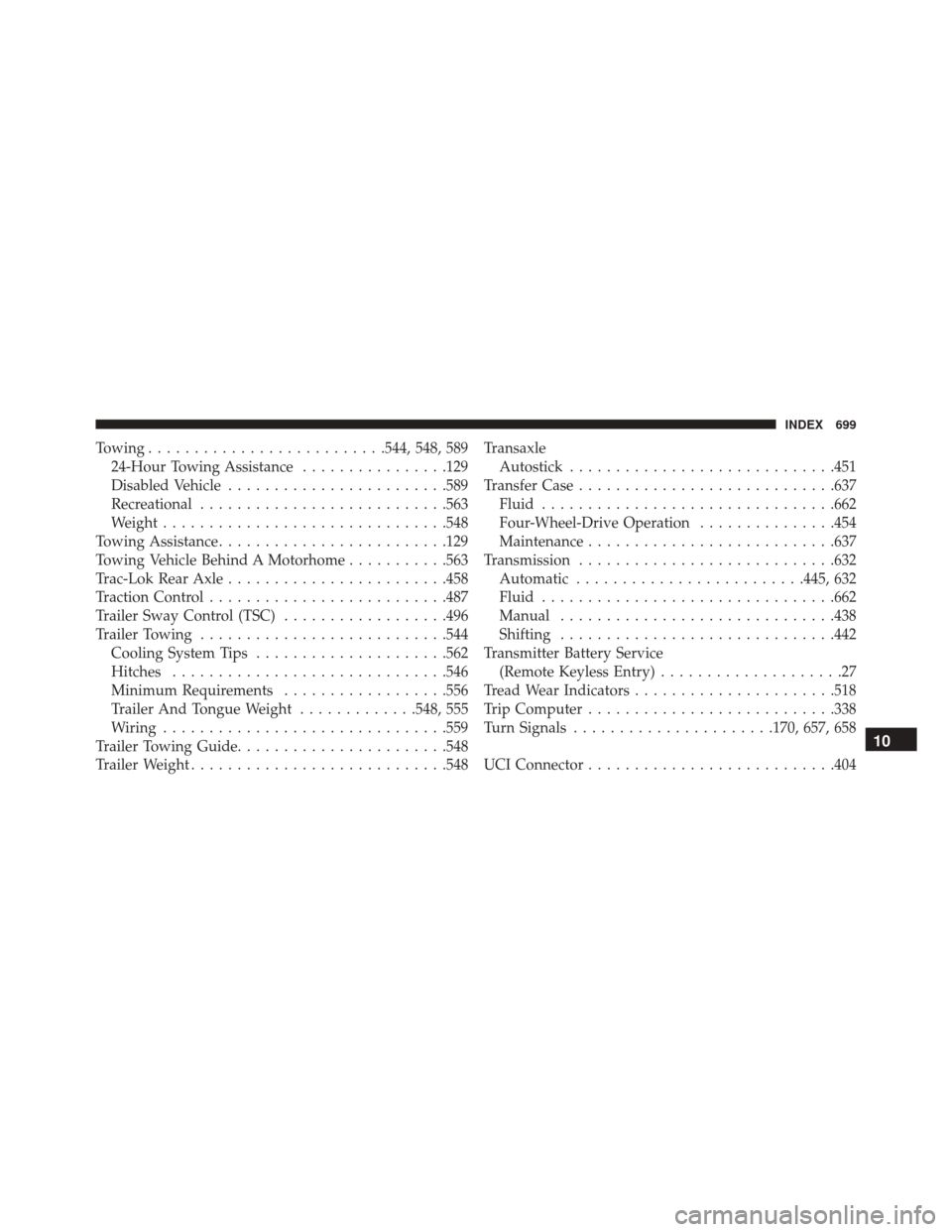
Towing......................... .544, 548, 589
24-Hour Towing Assistance ................129
Disabled Vehicle ....................... .589
Recreational .......................... .563
Weight .............................. .548
Towing Assistance ........................ .129
Towing Vehicle Behind A Motorhome ...........563
Trac-Lok Rear Axle ....................... .458
Traction Control ......................... .487
Trailer Sway Control (TSC) ..................496
Trailer Towing .......................... .544
Cooling System Tips .....................562
Hitches ............................. .546
Minimum Requirements ..................556
Trailer And Tongue Weight .............548, 555
Wiring .............................. .559
Trailer Towing Guide ...................... .548
Trailer Weight ........................... .548Transaxle
Autostick ............................ .451
Transfer Case ........................... .637
Fluid ............................... .662
Four-Wheel-Drive Operation ...............454
Maintenance .......................... .637
Transmission ........................... .632
Automatic ........................ .445, 632
Fluid ............................... .662
Manual ............................. .438
Shifting ............................. .442
Transmitter Battery Service (Remote Keyless Entry) ....................27
Tread Wear Indicators ..................... .518
Trip Computer .......................... .338
Turn Signals ..................... .170, 657, 658
UCI Connector .......................... .404
10
INDEX 699
Page 704 of 705

INSTALLATION OF RADIO TRANSMITTING
EQUIPMENT
Special design considerations are incorporated into this
vehicle’s electronic system to provide immunity to radio
frequency signals. Mobile two-way radios and telephone
equipment must be installed properly by trained person-
nel. The following must be observed during installation.
The positive power connection should be made directly
to the battery and fused as close to the battery as possible.
The negative power connection should be made to body
sheet metal adjacent to the negative battery connection.
This connection should not be fused.
Antennas for two-way radios should be mounted on the
roof or the rear area of the vehicle. Care should be used
in mounting antennas with magnet bases. Magnets may
affect the accuracy or operation of the compass on
vehicles so equipped.The antenna cable should be as short as practical and
routed away from the vehicle wiring when possible. Use
only fully shielded coaxial cable.
Carefully match the antenna and cable to the radio to
ensure a low Standing Wave Ratio (SWR).
Mobile radio equipment with output power greater than
normal may require special precautions.
All installations should be checked for possible interfer-
ence between the communications equipment and the
vehicle’s electronic systems.