JEEP WRANGLER 2016 JK / 3.G Owners Manual
Manufacturer: JEEP, Model Year: 2016, Model line: WRANGLER, Model: JEEP WRANGLER 2016 JK / 3.GPages: 705, PDF Size: 5.5 MB
Page 651 of 705
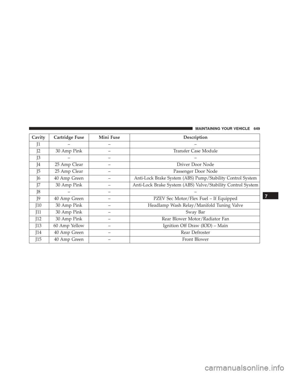
Cavity Cartridge Fuse Mini FuseDescription
J1 – – –
J2 30 Amp Pink –Transfer Case Module
J3 – – –
J4 25 Amp Clear –Driver Door Node
J5 25 Amp Clear –Passenger Door Node
J6 40 Amp Green –
Anti-Lock Brake System (ABS) Pump/Stability Control System
J7 30 Amp Pink– Anti-Lock Brake System (ABS) Valve/Stability Control System
J8 – – –
J9 40 Amp Green –PZEV Sec Motor/Flex Fuel – If Equipped
J10 30 Amp Pink –Headlamp Wash Relay/Manifold Tuning Valve
J11 30 Amp Pink – Sway Bar
J12 30 Amp Pink –Rear Blower Motor/Radiator Fan
J13 60 Amp Yellow –Ignition Off Draw (IOD) – Main
J14 40 Amp Green –Rear Defroster
J15 40 Amp Green – Front Blower
7
MAINTAINING YOUR VEHICLE 649
Page 652 of 705
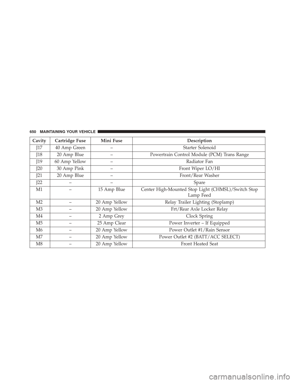
Cavity Cartridge Fuse Mini FuseDescription
J17 40 Amp Green –Starter Solenoid
J18 20 Amp Blue –Powertrain Control Module (PCM) Trans Range
J19 60 Amp Yellow – Radiator Fan
J20 30 Amp Pink –Front Wiper LO/HI
J21 20 Amp Blue –Front/Rear Washer
J22 – – Spare
M1 –15 Amp Blue Center High-Mounted Stop Light (CHMSL)/Switch Stop
Lamp Feed
M2 –20 Amp Yellow Relay Trailer Lighting (Stoplamp)
M3 –20 Amp Yellow Frt/Rear Axle Locker Relay
M4 –2 Amp Grey Clock Spring
M5 –25 Amp Clear Power Inverter – If Equipped
M6 –20 Amp Yellow Power Outlet #1/Rain Sensor
M7 –20 Amp Yellow Power Outlet #2 (BATT/ACC SELECT)
M8 –20 Amp Yellow Front Heated Seat
650 MAINTAINING YOUR VEHICLE
Page 653 of 705
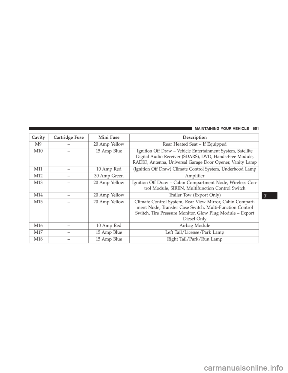
Cavity Cartridge Fuse Mini FuseDescription
M9 –20 Amp Yellow Rear Heated Seat – If Equipped
M10 –15 Amp Blue
Ignition Off Draw – Vehicle Entertainment System, Satellite
Digital Audio Receiver (SDARS), DVD, Hands-Free Module,
RADIO, Antenna, Universal Garage Door Opener, Vanity Lamp
M11 –10 Amp Red(Ignition Off Draw) Climate Control System, Underhood Lamp
M12 –30 Amp Green Amplifier
M13 –20 Amp Yellow Ignition Off Draw – Cabin Compartment Node, Wireless Con-
trol Module, SIREN, Multifunction Control Switch
M14 –20 Amp Yellow Trailer Tow (Export Only)
M15 –20 Amp Yellow Climate Control System, Rear View Mirror, Cabin Compart-
ment Node, Transfer Case Switch, Multi-Function Control
Switch, Tire Pressure Monitor, Glow Plug Module – Export Diesel Only
M16 –10 Amp Red Airbag Module
M17 –15 Amp Blue Left Tail/License/Park Lamp
M18 –15 Amp Blue Right Tail/Park/Run Lamp
7
MAINTAINING YOUR VEHICLE 651
Page 654 of 705
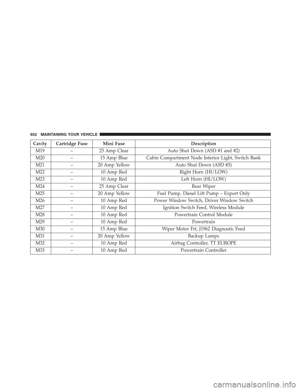
Cavity Cartridge Fuse Mini FuseDescription
M19 –25 Amp Clear Auto Shut Down (ASD #1 and #2)
M20 –15 Amp Blue Cabin Compartment Node Interior Light, Switch Bank
M21 –20 Amp Yellow Auto Shut Down (ASD #3)
M22 –10 Amp Red Right Horn (HI/LOW)
M23 –10 Amp Red Left Horn (HI/LOW)
M24 –25 Amp Clear Rear Wiper
M25 –20 Amp Yellow Fuel Pump, Diesel Lift Pump – Export Only
M26 –10 Amp Red Power Window Switch, Driver Window Switch
M27 –10 Amp Red Ignition Switch Feed, Wireless Module
M28 –10 Amp Red Powertrain Control Module
M29 –10 Amp Red Powertrain
M30 –15 Amp Blue Wiper Motor Frt, J1962 Diagnostic Feed
M31 –20 Amp Yellow Backup Lamps
M32 –10 Amp Red Airbag Controller, TT EUROPE
M33 –10 Amp Red Powertrain Controller
652 MAINTAINING YOUR VEHICLE
Page 655 of 705
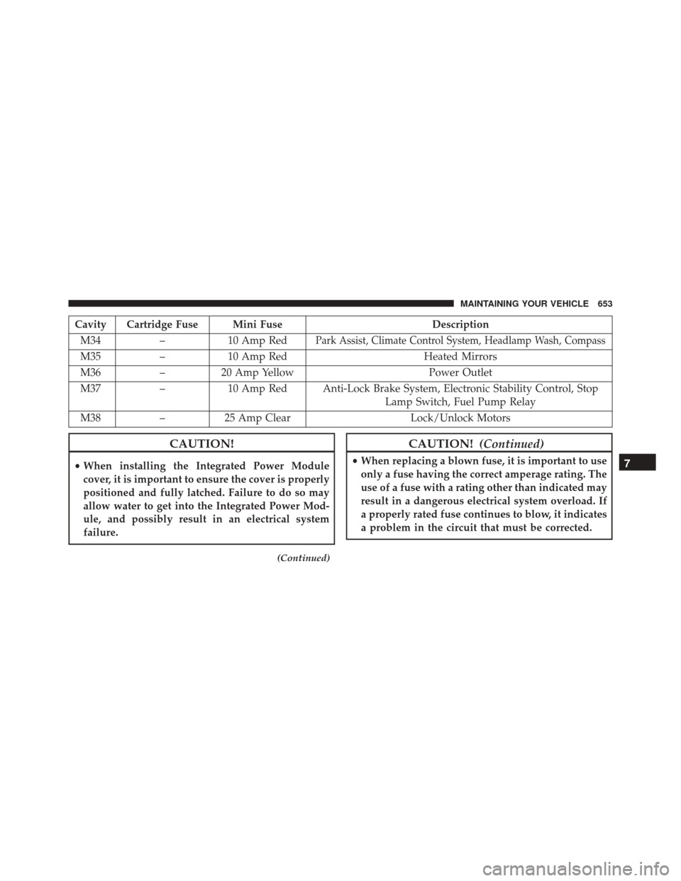
Cavity Cartridge Fuse Mini FuseDescription
M34 –10 Amp Red
Park Assist, Climate Control System, Headlamp Wash, Compass
M35 –10 Amp Red Heated Mirrors
M36 –20 Amp Yellow Power Outlet
M37 –10 Amp Red Anti-Lock Brake System, Electronic Stability Control, Stop
Lamp Switch, Fuel Pump Relay
M38 –25 Amp Clear Lock/Unlock Motors
CAUTION!
•When installing the Integrated Power Module
cover, it is important to ensure the cover is properly
positioned and fully latched. Failure to do so may
allow water to get into the Integrated Power Mod-
ule, and possibly result in an electrical system
failure.
(Continued)
CAUTION! (Continued)
•When replacing a blown fuse, it is important to use
only a fuse having the correct amperage rating. The
use of a fuse with a rating other than indicated may
result in a dangerous electrical system overload. If
a properly rated fuse continues to blow, it indicates
a problem in the circuit that must be corrected.7
MAINTAINING YOUR VEHICLE 653
Page 656 of 705
VEHICLE STORAGE
If you are leaving your vehicle dormant for more than 21
days, you may want to take steps to protect your battery.
You may:
•Remove Cartridge fuse #J13 in the Power Distribution
Center (PDC) labeled Ignition-Off Draw (IOD) and
store it in a safe location within the PDC. •
Or, disconnect the negative cable from the battery.
• Anytime you store your vehicle, or keep it out of
service (i.e., vacation) for two weeks or more, run the
air conditioning system at idle for about five minutes
in the fresh air and high blower setting. This will
ensure adequate system lubrication to minimize the
possibility of compressor damage when the system is
started again.
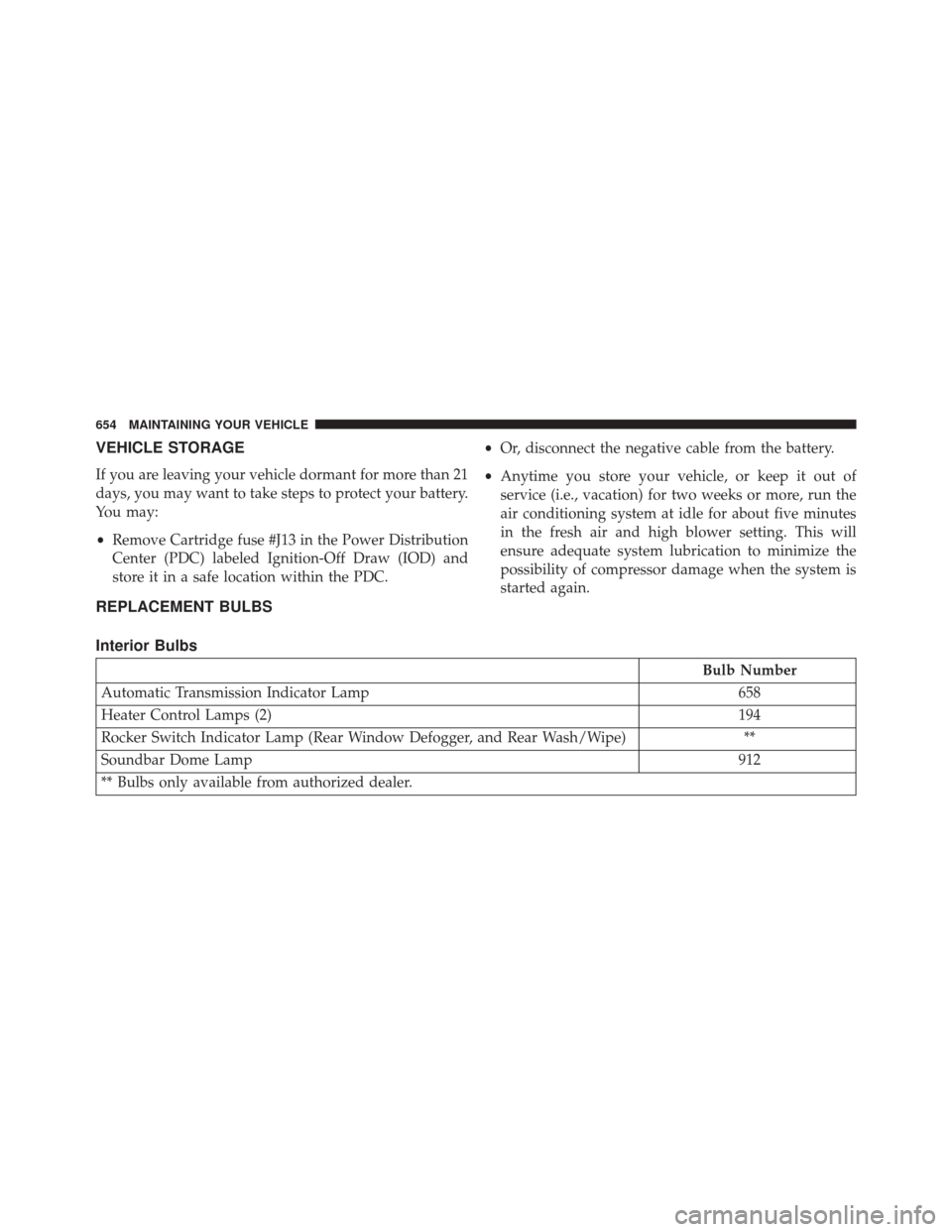
REPLACEMENT BULBS
Interior Bulbs
Bulb Number
Automatic Transmission Indicator Lamp 658
Heater Control Lamps (2) 194
Rocker Switch Indicator Lamp (Rear Window Defogger, and Rear Wash/Wipe) **
Soundbar Dome Lamp 912
** Bulbs only available from authorized dealer.
654 MAINTAINING YOUR VEHICLE
Page 657 of 705
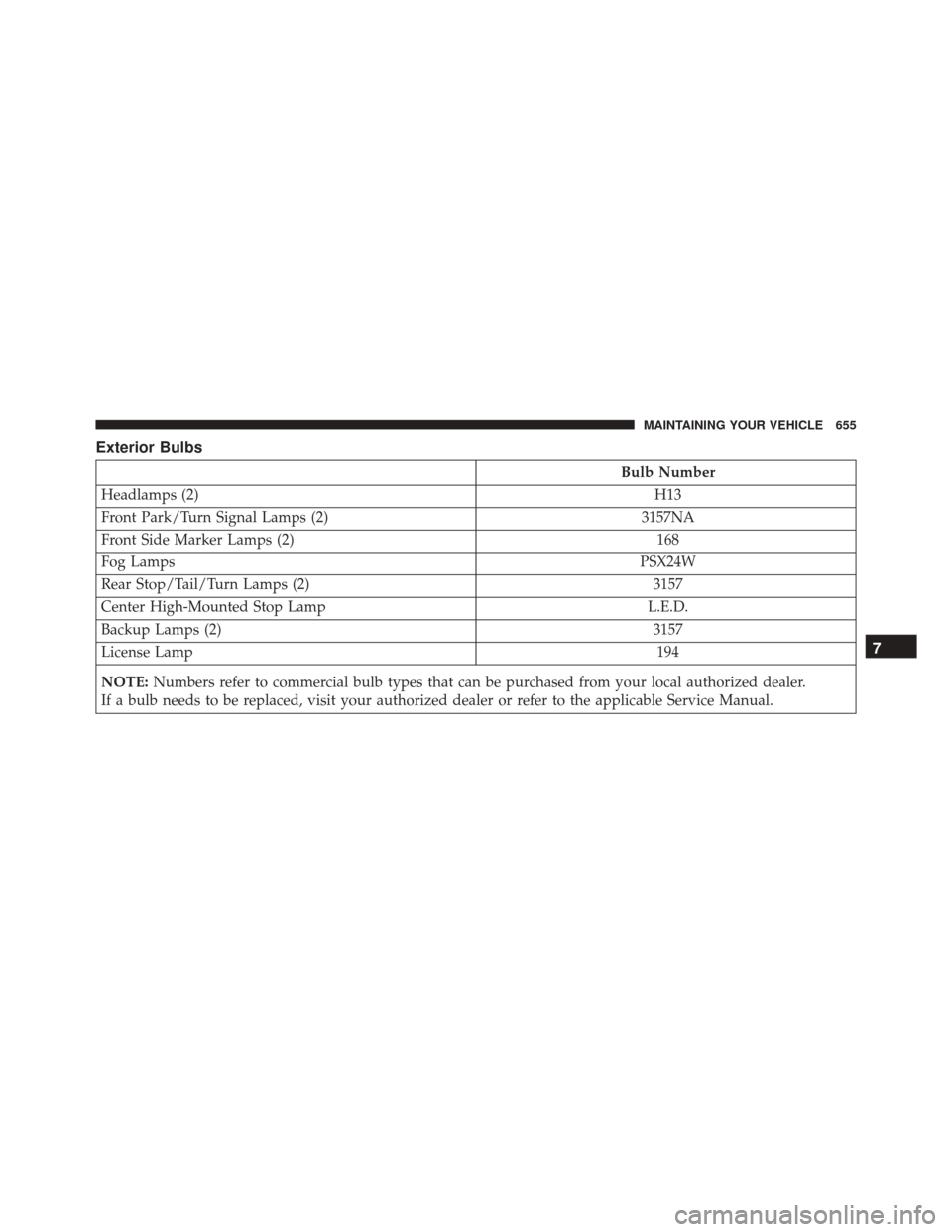
Exterior Bulbs
Bulb Number
Headlamps (2) H13
Front Park/Turn Signal Lamps (2) 3157NA
Front Side Marker Lamps (2) 168
Fog Lamps PSX24W
Rear Stop/Tail/Turn Lamps (2) 3157
Center High-Mounted Stop Lamp L.E.D.
Backup Lamps (2) 3157
License Lamp 194
NOTE: Numbers refer to commercial bulb types that can be purchased from your local authorized dealer.
If a bulb needs to be replaced, visit your authorized dealer or refer to the applicable Service Manual.
7
MAINTAINING YOUR VEHICLE 655
Page 658 of 705
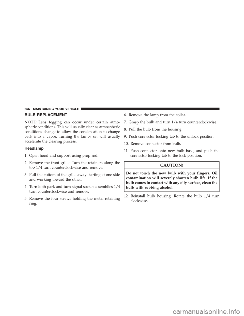
BULB REPLACEMENT
NOTE:Lens fogging can occur under certain atmo-
spheric conditions. This will usually clear as atmospheric
conditions change to allow the condensation to change
back into a vapor. Turning the lamps on will usually
accelerate the clearing process.
Headlamp
1. Open hood and support using prop rod.
2. Remove the front grille. Turn the retainers along the top 1/4 turn counterclockwise and remove.
3. Pull the bottom of the grille away starting at one side and working toward the other.
4. Turn both park and turn signal socket assemblies 1/4 turn counterclockwise and remove.
5. Remove the four screws holding the metal retaining ring. 6. Remove the lamp from the collar.
7. Grasp the bulb and turn 1/4 turn counterclockwise.
8. Pull the bulb from the housing.
9. Push connector locking tab to the unlock position.
10. Remove connector from bulb.
11. Push connector onto new bulb base, and push the
connector locking tab to the lock position.
CAUTION!
Do not touch the new bulb with your fingers. Oil
contamination will severely shorten bulb life. If the
bulb comes in contact with any oily surface, clean the
bulb with rubbing alcohol.
12. Reinstall bulb housing. Rotate the bulb 1/4 turn clockwise.
656 MAINTAINING YOUR VEHICLE
Page 659 of 705
Front Park/Turn Signal
1. Remove the front grille. Turn the retainers along thetop 1/4 turn counterclockwise and remove.
2. Pull the bottom of the grille away starting at one side and working toward the other.
3. Turn the socket assembly 1/4 turn counterclockwise and remove from housing. Pull the bulb straight from
the socket to replace.
Front Side Marker
1. Reach under the front fender flare and locate the frontside marker socket.
2. Turn the socket assembly counterclockwise 1/3 turn and remove it from the housing. Pull the bulb straight
from the socket to replace.
Front Fog Lamp
1. Reach under the vehicle to access the back of the frontfog lamp.
2. Disconnect the wire harness connector from the front fog lamp connector receptacle.
3. Firmly grasp the bulb by the two latch features and squeeze them together to unlock the bulb from the
back of the front fog lamp housing.
4. Pull the bulb straight out from the keyed opening in the housing and then connect the replacement bulb.
CAUTION!
Do not touch the new bulb with your fingers. Oil
contamination will severely shorten bulb life. If the
bulb comes in contact with any oily surface, clean the
bulb with rubbing alcohol.
7
MAINTAINING YOUR VEHICLE 657
Page 660 of 705
Rear Tail, Stop, Turn Signal, And Backup Lamp
1. Remove the two inboard screws attaching the tail lighthousing to the body. DO NOT REMOVE THE OUT-
BOARD SCREWS AT ANY TIME. 2. Separate the housing from the body by pushing the
lamp inboard while pulling the lamp away from the
body.
3. Rotate the appropriate socket 1/4 turn counterclock- wise, then remove it from the housing.
4. Pull the bulb straight from the socket to replace.
Center High-Mounted Stop Lamp (CHMSL)
The stop lamp is mounted on a bracket that extends
upward from the tailgate behind the spare tire. If service
is needed, obtain the LED/Cover Assembly from your
local authorized dealer.
1. Remove the spare tire.
2. Remove the four screws holding the lens/cover in place on the spare tire carrier.
3. Disconnect the wire harness from the back of the LED cover.
Inboard Screw Location
658 MAINTAINING YOUR VEHICLE