brake JEEP WRANGLER 2016 JK / 3.G Owner's Manual
[x] Cancel search | Manufacturer: JEEP, Model Year: 2016, Model line: WRANGLER, Model: JEEP WRANGLER 2016 JK / 3.GPages: 156, PDF Size: 8.82 MB
Page 111 of 156
Preparations For Jacking
1. Park on a firm, level surface. Avoid ice or slippery areas.
WARNING!
Do not attempt to change a tire on the side of the vehicle close to moving traffic,
pull far enough off the road to avoid being hit when operating the jack or changing
the wheel.
2. Turn on the Hazard Warning flasher.
3. Set the parking brake.
4. Shift the automatic transmission into PARK, or a manual transmission into REVERSE.
5. Turn the ignition to LOCK.
6. Block both the front and rear of the wheel diagonally opposite of the jacking position. For example, if changing the right front tire, block the left rear wheel.
NOTE:
Passengers should not remain in the ve-
hicle when the vehicle is being jacked.
Wheel Blocked
WHAT TO DO IN EMERGENCIES
109
Page 112 of 156
Jacking Instructions
WARNING!
Carefully follow these tire changing warnings to help prevent personal injury or
damage to your vehicle:
• Always park on a firm, level surface as far from the edge of the roadway aspossible before raising the vehicle.
• Turn on the Hazard Warning flasher.
• Block the wheel diagonally opposite the wheel to be raised.
• Set the parking brake firmly and set an automatic transmission in PARK; a
manual transmission in REVERSE.
• Never start or run the engine with the vehicle on a jack.
• Do not let anyone sit in the vehicle when it is on a jack.
• Do not get under the vehicle when it is on a jack. If you need to get under a
raised vehicle, take it to a service center where it can be raised on a lift.
• Only use the jack in the positions indicated and for lifting this vehicle during
a tire change.
• If working on or near a roadway, be extremely careful of motor traffic.
• To assure that spare tires, flat or inflated, are securely stowed, spares must be
stowed with the valve stem facing the ground.
CAUTION!
Do not attempt to raise the vehicle by jacking on locations other than those
indicated in the Jacking Instructions for this vehicle.
1. Remove the spare tire, jack and tools from the stored location.
2. Loosen (but do not remove) the wheel lug nuts by turning them to the left one turn while the wheel is still on the ground.
3. Assemble the jack and jacking tools. Connect the jack handle driver to the extension, then to the lug wrench.
Warning Label
WHAT TO DO IN EMERGENCIES
110
Page 116 of 156
WARNING!
•Take care to avoid the radiator cooling fan whenever the hood is raised. It can start
anytime the ignition switch is ON. You can be injured by moving fan blades.
• Remove any metal jewelry such as rings, watch bands and bracelets that couldmake an inadvertent electrical contact. You could be seriously injured.
• Batteries contain sulfuric acid that can burn your skin or eyes and generate
hydrogen gas which is flammable and explosive. Keep open flames or sparks
away from the battery.
1. Set the parking brake, shift the automatic transmission into PARK (manual transmission in NEUTRAL) and turn the ignition to LOCK.
2. Turn off the heater, radio, and all unnecessary electrical accessories.
3. If using another vehicle to jump-start the battery, park the vehicle within the jumper cables reach, set the parking brake and make sure the ignition is OFF.
WARNING!
Do not allow vehicles to touch each other as this could establish a ground
connection and personal injury could result.
Jump Starting Procedure
WARNING!
Failure to follow this jump-starting procedure could result in personal injury or
property damage due to battery explosion.
CAUTION!
Failure to follow these procedures could result in damage to the charging system
of the booster vehicle or the discharged vehicle.
Connecting The Jumper Cables
1. Connect the positive (+)end of the jumper cable to the positive (+)post of the
discharged vehicle.
2. Connect the opposite end of the positive (+)jumper cable to the positive (+)post
of the booster battery.
3. Connect the negative (-)end of the jumper cable to the negative (-)post of the
booster battery.
4. Connect the opposite end of the negative (-)jumper cable to a good engine ground
(exposed metal part of the discharged vehicle’s engine) away from the battery and
the fuel injection system.
WHAT TO DO IN EMERGENCIES
114
Page 118 of 156
CAUTION!
Tow hooks are for emergency use only, to rescue a vehicle stranded off road. Do not
use tow hooks for tow truck hookup or highway towing. You could damage your
vehicle. Tow straps are recommended when towing the vehicle, chains may cause
vehicle damage.
SHIFT LEVER OVERRIDE
If a malfunction occurs and the shift
lever cannot be moved out of the PARK
position, you can use the following pro-
cedure to temporarily move the shift le-
ver:
1. Turn the engine OFF.
2. Firmly apply the parking brake.
3. Using a small screwdriver or similartool, remove the shift lever override
access cover (located to the right of
the shift lever).
4. Turn the ignition to the ACC or ON/ RUN position, but do not start the
engine.
5. Push and maintain firm pressure on the brake pedal.
6. Insert the screwdriver or similar tool into the access port, and push and hold the override release lever down.
7. Move the shift lever to the NEUTRAL position.
8. The vehicle may then be started in NEUTRAL.
9. Reinstall the shift lever override access cover.
Shift Lever Override Location
WHAT TO DO IN EMERGENCIES
116
Page 121 of 156
FREEING A STUCK VEHICLE
If your vehicle becomes stuck in mud, sand or snow, it can often be moved using a
rocking motion. Turn the steering wheel right and left to clear the area around the
front wheels. Then shift back and forth between DRIVE and REVERSE (with
automatic transmission) or 2nd gear and REVERSE (with manual transmission),
while gently pressing the accelerator. Use the least amount of accelerator pedal
pressure that will maintain the rocking motion, without spinning the wheels, or racing
the engine.
CAUTION!
Racing the engine or spinning the wheels may lead to transmission overheating
and failure. Allow the engine to idle with the transmission in NEUTRAL for at least
one minute after every five rocking-motion cycles. This will minimize overheating
and reduce the risk of clutch or transmission failure during prolonged efforts to
free a stuck vehicle.
NOTE:
Push the "ESC Off" switch, to place the Electronic Stability Control (ESC) system in
"Partial Off" mode, before rocking the vehicle. Refer to “Electronic Brake Control” in
“Starting And Operating” in the Owner’s Manual on the DVD for further information.
Once the vehicle has been freed, push the "ESC Off" switch again to restore "ESC On"
mode.
CAUTION!
• When “rocking” a stuck vehicle by shifting between DRIVE/2nd gear and REVERSE, do not spin the wheels faster than 15 mph (24 km/h), or drivetrain
damage may result.
• Revving the engine or spinning the wheels too fast may lead to transmission
overheating and failure. It can also damage the tires. Do not spin the wheels
above 30 mph (48 km/h) while in gear (no transmission shifting occurring).
WARNING!
Fast spinning tires can be dangerous. Forces generated by excessive wheel speeds
may cause damage, or even failure, of the axle and tires. A tire could explode and
injure someone. Do not spin your vehicle's wheels faster than 30 mph (48 km/h)
or for longer than 30 seconds continuously without stopping when you are stuck
and do not let anyone near a spinning wheel, no matter what the speed.
WHAT TO DO IN EMERGENCIES
119
Page 124 of 156
ENGINE COMPARTMENT — 3.6L
1. Battery
2. Integrated Power Module (Fuses)
3. Engine Oil Dipstick
4. Engine Oil Fill
5. Brake Fluid Reservoir
MAINTAINING YOUR VEHICLE
122
Page 127 of 156
CAUTION!
•Mixing of engine coolant (antifreeze) other than specified Organic Additive Tech-
nology (OAT) engine coolant (antifreeze), may result in engine damage and may
decrease corrosion protection. Organic Additive Technology (OAT) engine coolant is
different and should not be mixed with Hybrid Organic Additive Technology (HOAT)
engine coolant (antifreeze) or any “globally compatible” coolant (antifreeze). If a
non-OAT engine coolant (antifreeze) is introduced into the cooling system in an
emergency, the cooling system will need to be drained, flushed, and refilled with
fresh OAT coolant (conforming to MS.90032), by an authorized dealer as soon as
possible.
• Do not use water alone or alcohol-based engine coolant (antifreeze) products.Do not use additional rust inhibitors or antirust products, as they may not be
compatible with the radiator engine coolant and may plug the radiator.
• This vehicle has not been designed for use with propylene glycol-based engine
coolant (antifreeze). Use of propylene glycol-based engine coolant (antifreeze)
is not recommended.
Chassis
Component Fluid, Lubricant, or Genuine Part
Automatic Transmission – If Equipped
Use only ATF+4 Automatic Transmission
Fluid. Failure to use ATF+4 fluid may affect
the function or performance of your transmis-
sion. We recommend MOPAR ATF+4 fluid.
Manual Transmission – If EquippedWe recommend you use MOPAR Manual
Transmission Lubricant meeting the require-
ments of FCA US Material Standard MS-
9224.
Transfer Case We recommend you use MOPAR ATF+4
Automatic Transmission Fluid.
Axle Differential (Front) We recommend you use MOPAR Gear &
Axle Lubricant (SAE 80W-90) (API GL-5).
Axle Differential (Rear)
226 RBI (Model 44) – We recommend you use
MOPAR Gear & Axle Lubricant (SAE 80W-90)
(API GL-5) or equivalent. For trailer towing,
use MOPAR Synthetic Gear & Axle Lubricant
(SAE 75W-140). Models equipped with Trac-
Lok require an additive.
Brake Master Cylinder We recommend you use MOPAR DOT 3
Brake Fluid, SAE J1703. If DOT 3, SAE
J1703 brake fluid is not available, then
DOT 4 is acceptable.
Power Steering Reservoir We recommend you use MOPAR Power
Steering Fluid +4, MOPAR ATF+4 Auto-
matic Transmission Fluid.
MAINTAINING YOUR VEHICLE
125
Page 129 of 156
Once A Month Or Before A Long Trip:
• Check engine oil level
• Check windshield washer fluid level
• Check the tire inflation pressures and look for unusual wear or damage
• Check the fluid levels of the coolant reservoir, brake master cylinder, powersteering and automatic transmission, and fill as needed
• Check function of all interior and exterior lights
Required Maintenance Intervals
Refer to the maintenance schedules on the following page for the required mainte-
nance intervals.
At Every Oil Change Interval As Indicated By Oil Change Indicator System:
• Change oil and filter
• Rotate the tires. Rotate at the first sign of irregular wear, even if it occurs before the oil
indicator system turns on.
• Inspect battery and clean and tighten terminals as required
• Inspect automatic transmission fluid if equipped with dipstick
• Inspect brake pads, shoes, rotors, drums, hoses and park brake
• Inspect engine cooling system protection and hoses
• Inspect exhaust system
• Inspect engine air cleaner if using in dusty or off-road conditions
• Inspect all door latches for presence of grease, reapply if necessary.
MAINTAINING YOUR VEHICLE
127
Page 130 of 156
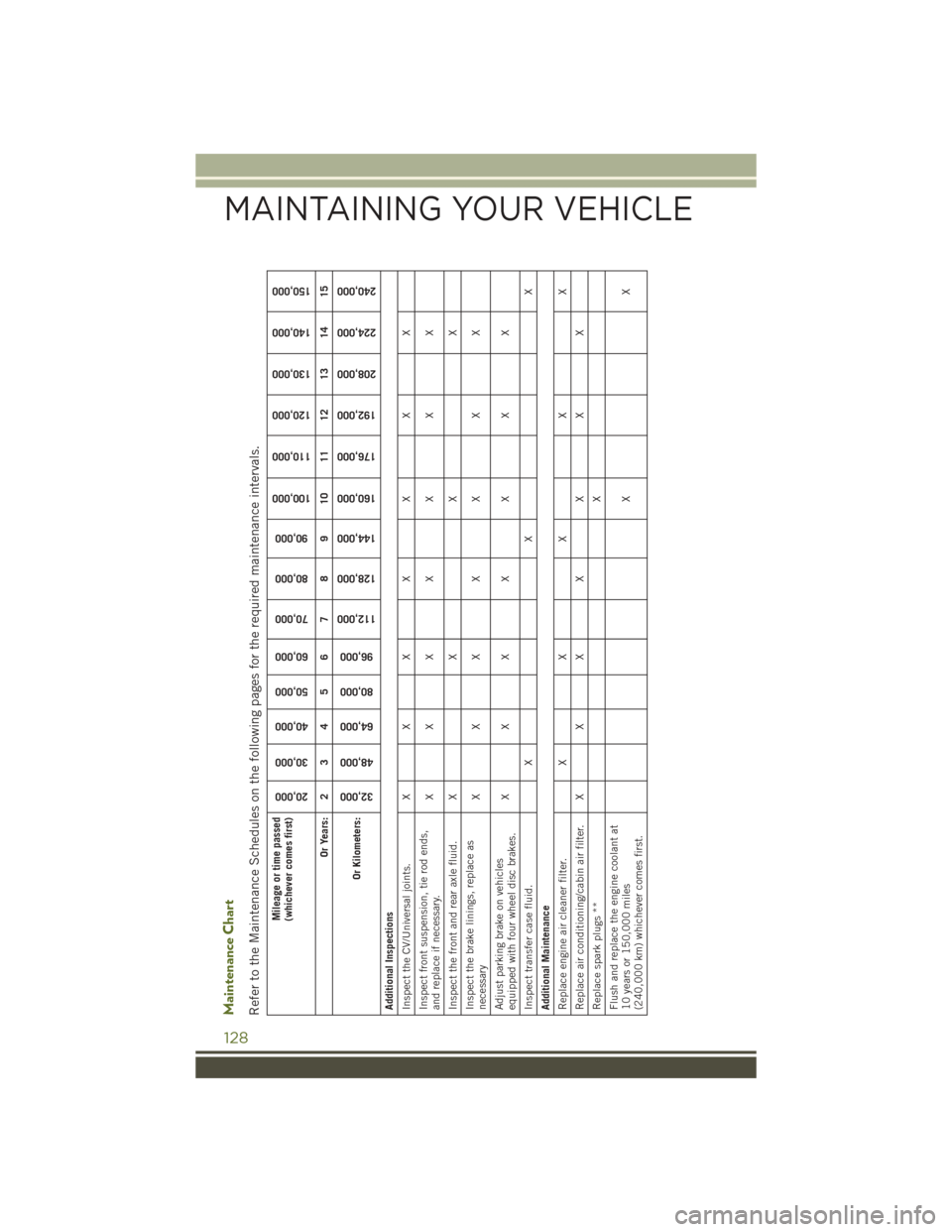
Maintenance ChartRefer to the Maintenance Schedules on the following pages for the required maintenance intervals.
Mileage or time passed
(whichever comes first)
20,000
30,000
40,000
50,000
60,000
70,000
80,000
90,000
100,000
110,000
120,000
130,000
140,000
150,000
Or Years: 2 3 4 5 6 7 8 9 10 11 12 13 14 15
Or Kilometers:
32,000
48,000
64,000
80,000
96,000
112,000
128,000
144,000
160,000
176,000
192,000
208,000
224,000
240,000
Additional Inspections
Inspect the CV/Universal joints. X X X X X X X
Inspect front suspension, tie rod ends,
and replace if necessary. XXX X X X X
Inspect the front and rear axle fluid. X X X X
Inspect the brake linings, replace as
necessary XXX X X X X
Adjust parking brake on vehicles
equipped with four wheel disc brakes. XXX X X X X
Inspect transfer case fluid. X X X
Additional Maintenance
Replace engine air cleaner filter. X X X X X
Replace air conditioning/cabin air filter. X X X X X X X
Replace spark plugs ** X
Flush and replace the engine coolant at
10 years or 150,000 miles
(240,000 km) whichever comes first. XX
MAINTAINING YOUR VEHICLE
128
Page 134 of 156
FUSES
WARNING!
• When replacing a blown fuse, always use an appropriate replacement fuse withthe same amp rating as the original fuse. Never replace a fuse with another
fuse of higher amp rating. Never replace a blown fuse with metal wires or any
other material. Failure to use proper fuses may result in serious personal injury,
fire and/or property damage.
• Before replacing a fuse, make sure that the ignition is off and that all the other
services are switched off and/or disengaged.
• If the replaced fuse blows again, contact an authorized dealer.
• If a general protection fuse for safety systems (air bag system, braking system),
power unit systems (engine system, gearbox system) or steering system blows,
contact an authorized dealer.
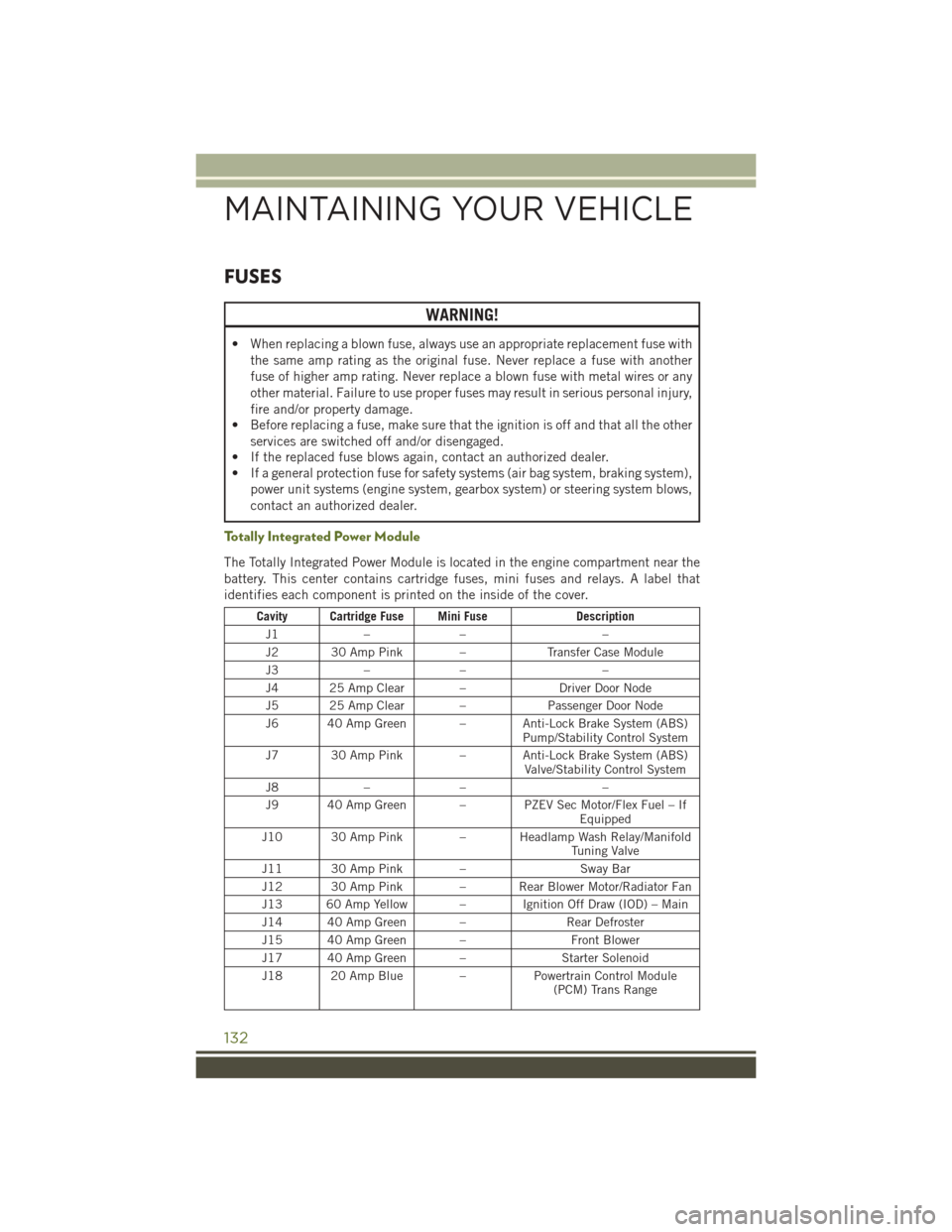
Totally Integrated Power Module
The Totally Integrated Power Module is located in the engine compartment near the
battery. This center contains cartridge fuses, mini fuses and relays. A label that
identifies each component is printed on the inside of the cover.
Cavity Cartridge Fuse Mini Fuse Description
J1 –– –
J2 30 Amp Pink – Transfer Case Module
J3 –– –
J4 25 Amp Clear – Driver Door Node
J5 25 Amp Clear – Passenger Door Node
J6 40 Amp Green – Anti-Lock Brake System (ABS) Pump/Stability Control System
J7 30 Amp Pink – Anti-Lock Brake System (ABS) Valve/Stability Control System
J8 –– –
J9 40 Amp Green – PZEV Sec Motor/Flex Fuel – If Equipped
J10 30 Amp Pink – Headlamp Wash Relay/Manifold Tuning Valve
J11 30 Amp Pink – Sway Bar
J12 30 Amp Pink – Rear Blower Motor/Radiator Fan
J13 60 Amp Yellow – Ignition Off Draw (IOD) – Main
J14 40 Amp Green – Rear Defroster
J15 40 Amp Green – Front Blower
J17 40 Amp Green – Starter Solenoid
J18 20 Amp Blue – Powertrain Control Module
(PCM) Trans Range
MAINTAINING YOUR VEHICLE
132