automatic transmission JEEP WRANGLER 2020 Owner handbook (in English)
[x] Cancel search | Manufacturer: JEEP, Model Year: 2020, Model line: WRANGLER, Model: JEEP WRANGLER 2020Pages: 276, PDF Size: 4.47 MB
Page 15 of 276
KEY FOB
Your vehicle uses a key start ignition system.
The ignition system consists of a Remote
Keyless Entry (RKE) key fob with an ignition
switch.
Key Fob
The key fob allows you to lock or unlock the
doors and liftgate from distances up to ap-
proximately 66 ft (20 m) using a handheld
key fob. The key fob does not need to be
pointed at the vehicle to activate the system.
NOTE:
In the ON/RUN position, the lock button is
disabled. Only the unlock button is enabled.
To Unlock The Doors And Swing Gate
Push and release the key fob unlock button
once to unlock the driver's door only, or twice
to unlock all the doors and swing gate. Whenthe key fob unlock button is pushed, the
Illuminated Entry will initiate, and the turn
signal lights will flash twice.
To Lock The Doors And Swing Gate
Push and release the lock button on the key
fob to lock all doors. The turn signals will
flash to acknowledge the lock signal.
IGNITION SWITCH
Ignition Key Removal
1. Place the gear selector in PARK (if
equipped with an automatic
transmission).
2. Turn the ignition switch to the ACC (Ac-
cessory) position.
3. Push the key and cylinder inward and
rotate the key to the LOCK position.
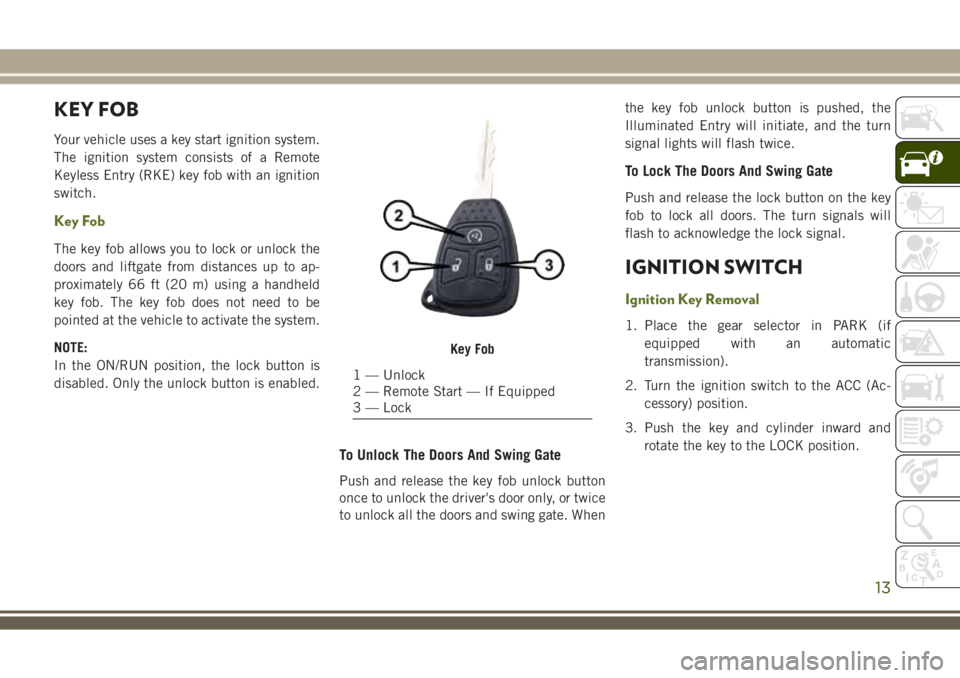
Key Fob
1 — Unlock
2 — Remote Start — If Equipped
3 — Lock
13
Page 16 of 276
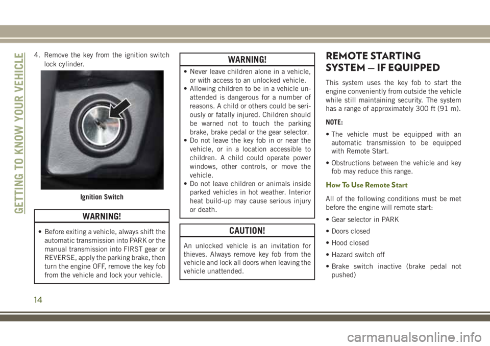
4. Remove the key from the ignition switch
lock cylinder.
WARNING!
• Before exiting a vehicle, always shift the
automatic transmission into PARK or the
manual transmission into FIRST gear or
REVERSE, apply the parking brake, then
turn the engine OFF, remove the key fob
from the vehicle and lock your vehicle.
WARNING!
• Never leave children alone in a vehicle,
or with access to an unlocked vehicle.
• Allowing children to be in a vehicle un-
attended is dangerous for a number of
reasons. A child or others could be seri-
ously or fatally injured. Children should
be warned not to touch the parking
brake, brake pedal or the gear selector.
• Do not leave the key fob in or near the
vehicle, or in a location accessible to
children. A child could operate power
windows, other controls, or move the
vehicle.
• Do not leave children or animals inside
parked vehicles in hot weather. Interior
heat build-up may cause serious injury
or death.
CAUTION!
An unlocked vehicle is an invitation for
thieves. Always remove key fob from the
vehicle and lock all doors when leaving the
vehicle unattended.
REMOTE STARTING
SYSTEM — IF EQUIPPED
This system uses the key fob to start the
engine conveniently from outside the vehicle
while still maintaining security. The system
has a range of approximately 300 ft (91 m).
NOTE:
• The vehicle must be equipped with an
automatic transmission to be equipped
with Remote Start.
• Obstructions between the vehicle and key
fob may reduce this range.
How To Use Remote Start
All of the following conditions must be met
before the engine will remote start:
• Gear selector in PARK
• Doors closed
• Hood closed
• Hazard switch off
• Brake switch inactive (brake pedal not
pushed)Ignition Switch
GETTING TO KNOW YOUR VEHICLE
14
Page 31 of 276
Daytime Running Lights — If Equipped
The headlights come on at a low intensity level
when shifted into any position other than PARK
(auto transmission) or when the vehicle begins
to move (manual transmission).
NOTE:
The Daytime Running Light, on the same side
of the vehicle as the active turn signal, will
turn off automatically when a turn signal is in
operation and turn on again when the turn
signal is not operating.
High/Low Beam Switch
Push the multifunction lever toward the in-
strument panel to switch the headlights to
high beams. Pulling the multifunction lever
back toward the steering wheel will return the
lights to low beams.
Flash-To-Pass
You can signal another vehicle with your
headlights by lightly pulling the multifunc-
tion lever toward you. This will cause the high
beam headlights to turn on, and remain on,
until the lever is released.
Automatic Headlights — If Equipped
This system automatically turns the head-
lights on or off according to ambient light
levels. To turn the system on, turn the end of
the multifunction lever to the AUTO position
(third detent). When the system is on, the
Headlight Time Delay feature is also on. This
means the headlights will stay on for up to
90 seconds after you turn the ignition switch
to the LOCK position. To turn the Automatic
System off, turn the end of the multifunction
lever out of the AUTO position.
NOTE:
The engine must be running before the head-
lights will turn on in the Automatic mode.
Front Fog Lights
The front fog light switch is located on the
multifunction lever. To activate the front fog
lights, turn on the parking or low beam head-
lights and pull out the end of the lever.NOTE:
The fog lights will only operate with the park-
ing lights or the headlights on low beam.
Selecting high beam headlights will turn off
the fog lights.
Rear Fog Lights — If Equipped
The rear fog lights may be operated, as de-
sired, when visibility is poor due to fog. To
activate the rear fog lights, turn on the low
beam, high beam, or front fog lamps, pull out
the end of the multifunction lever and rotate
the lever to the last detent.
Turn Signals
Move the multifunction lever up or down and
the arrows on each side of the instrument
cluster flash to show proper operation of the
front and rear turn signal lights.
29
Page 59 of 276
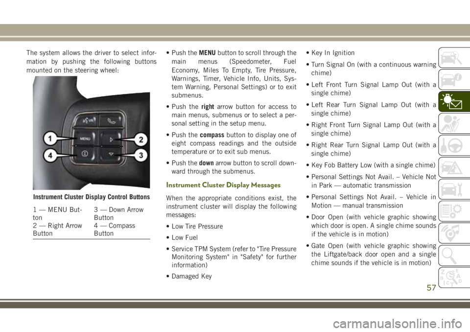
The system allows the driver to select infor-
mation by pushing the following buttons
mounted on the steering wheel:• Push theMENUbutton to scroll through the
main menus (Speedometer, Fuel
Economy, Miles To Empty, Tire Pressure,
Warnings, Timer, Vehicle Info, Units, Sys-
tem Warning, Personal Settings) or to exit
submenus.
• Push therightarrow button for access to
main menus, submenus or to select a per-
sonal setting in the setup menu.
• Push thecompassbutton to display one of
eight compass readings and the outside
temperature or to exit sub menus.
• Push thedownarrow button to scroll down-
ward through the submenus.
Instrument Cluster Display Messages
When the appropriate conditions exist, the
instrument cluster will display the following
messages:
• Low Tire Pressure
• Low Fuel
• Service TPM System (refer to "Tire Pressure
Monitoring System" in "Safety" for further
information)
• Damaged Key• Key In Ignition
• Turn Signal On (with a continuous warning
chime)
• Left Front Turn Signal Lamp Out (with a
single chime)
• Left Rear Turn Signal Lamp Out (with a
single chime)
• Right Front Turn Signal Lamp Out (with a
single chime)
• Right Rear Turn Signal Lamp Out (with a
single chime)
• Key Fob Battery Low (with a single chime)
• Personal Settings Not Avail. – Vehicle Not
in Park — automatic transmission
• Personal Settings Not Avail. – Vehicle in
Motion — manual transmission
• Door Open (with vehicle graphic showing
which door is open. A single chime sounds
if the vehicle is in motion)
• Gate Open (with vehicle graphic showing
the Liftgate/back door open and a single
chime sounds if the vehicle is in motion)Instrument Cluster Display Control Buttons
1 — MENU But-
ton3 — Down Arrow
Button
2 — Right Arrow
Button4 — Compass
Button
57
Page 60 of 276
• Check Gascap (refer to “Refueling The Ve-
hicle” in “Starting And Operating” for fur-
ther information)
• Oil Change Required (with a single chime)
• ECO (Fuel Saver Indicator) — if equipped
Gear Shift Indicator (GSI) — If Equipped
The Gear Shift Indicator (GSI) system is en-
abled on vehicles with a manual transmis-
sion, or when a vehicle with an automatic
transmission is in manual shift mode. The
GSI provides the driver with a visual indica-
tion when the recommended gear shift point
has been reached. This indication notifies
the driver that changing gear will allow a
reduction in fuel consumption. When the up
shift indicator is shown on the display, the
GSI is advising the driver to engage a higher
gear. When the down shift indicator is shown
on the display, the GSI is advising the driver
to engage a lower gear.
The GSI indicator remains illuminated until
the driver changes gear, or the driving condi-
tions return to a situation where changing gear
is not required to improve fuel consumption.
Oil Change Required
Your vehicle is equipped with an engine oil
change indicator system. The “Oil Change
Required” message will display in the instru-
ment cluster display for approximately
10 seconds after a single chime has sounded
to indicate the next scheduled oil change
interval. The engine oil change indicator sys-
tem is duty cycle based, which means the
engine oil change interval may fluctuate de-
pendent upon your personal driving style.
Unless reset, this message will continue to
display each time you turn the ignition switch
to the ON position. To turn off the message
temporarily, push and release theMENUbut-
ton. To reset the oil change indicator system
(after performing the scheduled mainte-
nance), perform the following procedure:
WARNING LIGHTS AND
MESSAGES
The warning/indicator lights will illuminate in
the instrument panel together with a dedi-
cated message and/or acoustic signal when
applicable. These indications are indicativeand precautionary and as such must not be
considered as exhaustive and/or alternative
to the information contained in the Owner’s
Manual, which you are advised to read care-
fully in all cases. Always refer to the informa-
tion in this chapter in the event of a failure
indication. All active telltales will display first
if applicable. The system check menu may
appear different based upon equipment op-
tions and current vehicle status. Some tell-
tales are optional and may not appear.
Red Warning Lights
— Air Bag Warning Light
This light indicates a fault with the air bag,
and will turn on for four to eight seconds as a
bulb check when the ignition is placed in the
ON/RUN or ACC/ON/RUN position. This light
will illuminate with a single chime when a
fault with the air bag has been detected, it
will stay on until the fault is cleared. If the
light is either not on during startup, stays on,
or turns on while driving, have the system
inspected at an authorized dealer as soon as
possible.
GETTING TO KNOW YOUR INSTRUMENT PANEL
58
Page 64 of 276
and automatic transmission control systems.
The light will illuminate when the ignition is
in the ON/RUN position before engine start.
If the bulb does not come on when turning
the ignition switch from OFF to ON/RUN,
have the condition checked promptly.
Certain conditions, such as a loose or missing
gas cap, poor quality fuel, etc., may illumi-
nate the light after engine start. The vehicle
should be serviced if the light stays on
through several typical driving styles. In most
situations, the vehicle will drive normally and
will not require towing.
When the engine is running, the MIL may
flash to alert serious conditions that could
lead to immediate loss of power or severe
catalytic converter damage. The vehicle
should be serviced as soon as possible if this
occurs.
WARNING!
A malfunctioning catalytic converter, as
referenced above, can reach higher tem-
peratures than in normal operating condi-
tions. This can cause a fire if you drive
WARNING!
slowly or park over flammable substances
such as dry plants, wood, cardboard, etc.
This could result in death or serious injury
to the driver, occupants or others.
CAUTION!
Prolonged driving with the Malfunction
Indicator Light (MIL) on could cause dam-
age to the vehicle control system. It also
could affect fuel economy and driveability.
If the MIL is flashing, severe catalytic
converter damage and power loss will soon
occur. Immediate service is required.
— Tire Pressure Monitoring System
(TPMS) Warning Light
The warning light switches on and a message
is displayed to indicate that the tire pressure
is lower than the recommended value and/or
that slow pressure loss is occurring. In these
cases, optimal tire duration and fuel con-
sumption may not be guaranteed.Should one or more tires be in the condition
mentioned above, the display will show the
indications corresponding to each tire in
sequence.
CAUTION!
Do not continue driving with one or more
flat tires as handling may be compro-
mised. Stop the vehicle, avoiding sharp
braking and steering. If a tire puncture
occurs, repair immediately using the dedi-
cated tire repair kit and contact your au-
thorized dealer as soon as possible.
Each tire, including the spare (if provided),
should be checked monthly when cold and
inflated to the inflation pressure recom-
mended by the vehicle manufacturer on the
vehicle placard or tire inflation pressure la-
bel. (If your vehicle has tires of a different
size than the size indicated on the vehicle
placard or tire inflation pressure label, you
should determine the proper tire inflation
pressure for those tires.)
GETTING TO KNOW YOUR INSTRUMENT PANEL
62
Page 78 of 276
WARNING!
Many factors, such as vehicle loading,
road conditions and driving conditions,
influence the chance that wheel lift or
rollover may occur. ERM cannot prevent
all wheel lift or roll overs, especially those
that involve leaving the roadway or striking
objects or other vehicles. The capabilities
of an ERM-equipped vehicle must never
be exploited in a reckless or dangerous
manner which could jeopardize the user's
safety or the safety of others.
Trailer Sway Control (TSC)
TSC uses sensors in the vehicle to recognize
an excessively swaying trailer and will take
the appropriate actions to attempt to stop the
sway. TSC will become active automatically
once an excessively swaying trailer is recog-
nized.NOTE:
TSC cannot stop all trailers from swaying.
Always use caution when towing a trailer and
follow the trailer tongue weight recommenda-
tions. Refer to “Trailer Towing” in “Starting
And Operating” for further information.
When TSC is functioning, the “ESC
Activation/Malfunction Indicator Light” will
flash, the engine power may be reduced and
you may feel the brakes being applied to
individual wheels to attempt to stop the
trailer from swaying. TSC is disabled when
the ESC system is in the “Partial Off” or “Full
Off” modes.WARNING!
If TSC activates while driving, slow the
vehicle down, stop at the nearest safe
location, and adjust the trailer load to
eliminate trailer sway.
Hill Descent Control (HDC) — If Equipped
HDC is only intended for low speed off-road
driving. HDC maintains vehicle speed while
descending hills in off-road driving condi-
tions by applying the brakes when necessary.
The symbol indicates the status
of the Hill Descent Control
(HDC) feature. The lamp will be
on solid when HDC is armed.
HDC can only be armed when the
transfer case is in the “4WD LOW” position
and the vehicle speed is less then 30 mph
(48 km/h). If these conditions are not met
while attempting to use the HDC feature, the
HDC indicator light will flash on/off.
When enabled, HDC senses the terrain and acti-
vates when the vehicle is descending a hill. HDC
speed may be adjusted by the driver to suit the
driving conditions. The speed corresponds to the
transmission gear selected.
Gear Approximate HDC Set
Speed
1st 1 mph (1.5 km/h)
2nd 2.5 mph (4 km/h)
SAFETY
76
Page 117 of 276
STARTING AND OPERATING
STARTING THE ENGINE.......117
Manual Transmission — If Equipped . .117
Automatic Transmission — If
Equipped...................117
Normal Starting — Gasoline Engine . . .117
Extreme Cold Weather (Below –22°F Or
−30°C)....................117
If Engine Fails To Start..........118
After Starting.................119
Normal Starting — Diesel Engine. . . .119
ENGINE BREAK-IN RECOMMENDA-
TIONS....................121
PARKING BRAKE............121
MANUAL TRANSMISSION — IF
EQUIPPED.................123
Shifting....................123
Downshifting.................124
Reverse Shifting...............125
AUTOMATIC TRANSMISSION — IF
EQUIPPED................126
Key Ignition Park Interlock........127
Brake/Transmission Shift Interlock
System....................127
Five-Speed Automatic Transmission — If
Equipped...................127
Autostick...................128
FOUR–WHEEL DRIVE OPERATION
(COMMAND-TRAC I OR ROCK-
TRAC)....................129
Operating Instructions/Precautions . . .129
Shift Positions................130
Shifting Procedures.............131
Trac-Lok Rear Axle — If Equipped . . .132
Axle Lock (Tru-Lok) — Rubicon
Models....................132
Electronic Sway Bar Disconnect — If
Equipped...................133
STOP/START SYSTEM — DIESEL
MODELS WITH MANUAL TRANS-
MISSION ONLY..............134
Automatic Mode...............134
SPEED CONTROL............136
To Activate..................137
To Set A Desired Speed..........137
To Vary The Speed Setting.........137
To Accelerate For Passing.........138
To Resume Speed.............138
To Deactivate................138
REFUELING THE VEHICLE.....139
Fuel Filler Cap...............139
Loose Fuel Filler Cap Message......140
STARTING AND OPERATING
115
Page 119 of 276
STARTING THE ENGINE
Before starting your vehicle, adjust your seat,
adjust both inside and outside mirrors, and
fasten your seat belts.
WARNING!
• When exiting the vehicle, always remove
the key fob from the ignition and lock
your vehicle.
• Never leave children alone in a vehicle,
or with access to an unlocked vehicle.
• Allowing children to be in a vehicle un-
attended is dangerous for a number of
reasons. A child or others could be seri-
ously or fatally injured. Children should
be warned not to touch the parking
brake, brake pedal or the gear selector.
• Do not leave the key fob in or near the
vehicle, or in a location accessible to
children. A child could operate power
windows, other controls, or move the
vehicle.
• Do not leave children or animals inside
parked vehicles in hot weather. Interior
WARNING!
heat build-up may cause serious injury
or death.
Manual Transmission — If Equipped
Apply the parking brake, place the gear se-
lector in NEUTRAL, and press the clutch
pedal before starting the vehicle. This vehicle
is equipped with a clutch interlocking igni-
tion system. It will not start unless the clutch
pedal is pressed to the floor.
Four-Wheel Drive Models Only
In 4L mode, this vehicle will start regardless
of whether or not the clutch pedal is pressed
to the floor. This feature enhances off-road
performance by allowing the vehicle to start
when in 4L without having to press the clutch
pedal. The “4WD Low Indicator Light” will
illuminate when the transfer case has been
shifted into this mode.
Automatic Transmission — If Equipped
Start the vehicle with the gear selector in the
PARK position (vehicle can also be started in
NEUTRAL). Apply the brake before shifting
to any driving range.
Normal Starting — Gasoline Engine
NOTE:
Normal starting of either a cold or a warm
engine is obtained without pumping or press-
ing the accelerator pedal.
Cycle the ignition switch to the START posi-
tion and release when the engine starts. If the
engine fails to start within 10 seconds, cycle
the ignition switch to the LOCK/OFF position,
wait 10 to 15 seconds, then repeat the “Nor-
mal Starting” procedure.
Extreme Cold Weather (Below –22°F Or
−30°C)
To ensure reliable starting at these tempera-
tures, use of an externally powered electric
engine block heater (available from your au-
thorized dealer) is recommended.
117
Page 120 of 276
If Engine Fails To Start
WARNING!
• Never pour fuel or other flammable liq-
uid into the throttle body air inlet open-
ing in an attempt to start the vehicle.
This could result in flash fire causing
serious personal injury.
• Do not attempt to push or tow your
vehicle to get it started. Vehicles
equipped with an automatic transmis-
sion cannot be started this way. Un-
burned fuel could enter the catalytic
converter and once the engine has
started, ignite and damage the converter
and vehicle.
• If the vehicle has a discharged battery,
booster cables may be used to obtain a
start from a booster battery or the battery
in another vehicle. This type of start can
be dangerous if done improperly. Refer
to “Jump Starting Procedure” in “In
Case Of Emergency” for further informa-
tion.Without Tip Start — Manual Transmission Only
If the engine fails to start after you have
followed the “Normal Starting” or “Extreme
Cold Weather” procedures, it may be flooded.
Push the accelerator pedal all the way to the
floor and hold it there while cranking the
engine. This should clear any excess fuel in
case the engine is flooded.
CAUTION!
To prevent damage to the starter, do not
crank the engine for more than 15 seconds
at a time. Wait 10 to 15 seconds before
trying again.
If the engine has been flooded, it may start to
run, but not have enough power to continue
running when the key is released. If this
occurs, continue cranking with the accelera-
tor pedal pushed all the way to the floor.
Release the accelerator pedal and the key
once the engine is running smoothly.If the engine shows no sign of starting after
two 15-second periods of cranking with the
accelerator pedal held to the floor, repeat the
“Normal Starting” or “Extreme Cold
Weather” procedures.
With Tip Start — Automatic Transmission Only
If the engine fails to start after you have
followed the “Normal Starting” or “Extreme
Cold Weather” procedures, it may be flooded.
To clear any excess fuel, push the accelerator
pedal all the way to the floor and hold it.
Then, turn the ignition switch to the START
position and release it as soon as the starter
engages. The starter motor will disengage
automatically in 10 seconds. Once this oc-
curs, release the accelerator pedal, turn the
ignition switch to the LOCK position, wait
10 to 15 seconds, then repeat the “Normal
Starting” procedure.
CAUTION!
To prevent damage to the starter, wait
10 to 15 seconds before trying again.
STARTING AND OPERATING
118