change time JEEP WRANGLER 2020 Owner handbook (in English)
[x] Cancel search | Manufacturer: JEEP, Model Year: 2020, Model line: WRANGLER, Model: JEEP WRANGLER 2020Pages: 276, PDF Size: 4.47 MB
Page 13 of 276
GETTING TO KNOW YOUR VEHICLE
KEYFOB...................13
KeyFob.....................13
IGNITION SWITCH............13
Ignition Key Removal............13
REMOTE STARTING SYSTEM — IF
EQUIPPED.................14
How To Use Remote Start..........14
Remote Start Abort Message........15
To Enter Remote Start............15
To Exit Remote Start Mode Without Driving
The Vehicle...................16
To Exit Remote Start Mode And Drive The
Vehicle.....................16
SENTRY KEY................16
Replacement Key Fobs...........17
Customer Key Programming........17
VEHICLE SECURITY ALARM — IF
EQUIPPED.................18
Rearming The System............18
To Arm The System.............18
To Disarm The System............18
DOORS....................19
Upper Half Door Window Removal — If
Equipped....................19
Front Door Removal..............19
Rear Door Removal (Four-Door Models) . .20
SEATS ....................21
Heated Seats — If Equipped........21
60/40 Split Folding Rear Seat —
Four Door Models..............22
Front Passenger Easy Entry Seat —
Two Door Models...............23
Tip ‘n Slide Seats — Two Door Models . .24
Removing The Rear Seat — Two Door
Models.....................24
HEAD RESTRAINTS...........25
Front Head Restraints............25
Rear Head Restraints — 2 Door Model . .26
Rear Head Restraints — 4 Door Model . .27
STEERING WHEEL............28
Tilt Steering Column.............28
MIRRORS..................28
Heated Mirrors — If Equipped.......28
EXTERIOR LIGHTS............28
Headlights And Parking Lights.......28
Daytime Running Lights — If Equipped .29
High/Low Beam Switch...........29
Flash-To-Pass.................29
Automatic Headlights — If Equipped . .29
Front Fog Lights...............29
Rear Fog Lights — If Equipped......29
Turn Signals..................29
Lane Change Assist — If Equipped....30
Lights-On Reminder.............30
Headlight Leveling System — If
Equipped...................30
WINDSHIELD WIPERS AND WASH-
ERS ......................30
Windshield Wiper Operation.........31
Rear Window Wiper/Washer — If
Equipped...................32
GETTING TO KNOW YOUR VEHICLE
11
Page 24 of 276
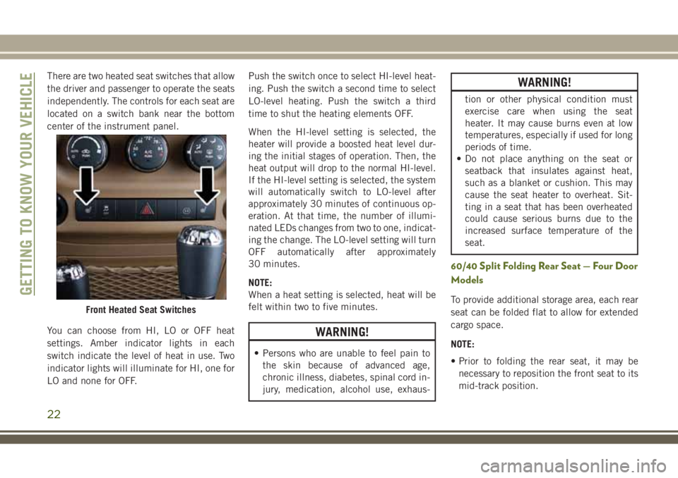
There are two heated seat switches that allow
the driver and passenger to operate the seats
independently. The controls for each seat are
located on a switch bank near the bottom
center of the instrument panel.
You can choose from HI, LO or OFF heat
settings. Amber indicator lights in each
switch indicate the level of heat in use. Two
indicator lights will illuminate for HI, one for
LO and none for OFF.Push the switch once to select HI-level heat-
ing. Push the switch a second time to select
LO-level heating. Push the switch a third
time to shut the heating elements OFF.
When the HI-level setting is selected, the
heater will provide a boosted heat level dur-
ing the initial stages of operation. Then, the
heat output will drop to the normal HI-level.
If the HI-level setting is selected, the system
will automatically switch to LO-level after
approximately 30 minutes of continuous op-
eration. At that time, the number of illumi-
nated LEDs changes from two to one, indicat-
ing the change. The LO-level setting will turn
OFF automatically after approximately
30 minutes.
NOTE:
When a heat setting is selected, heat will be
felt within two to five minutes.
WARNING!
• Persons who are unable to feel pain to
the skin because of advanced age,
chronic illness, diabetes, spinal cord in-
jury, medication, alcohol use, exhaus-
WARNING!
tion or other physical condition must
exercise care when using the seat
heater. It may cause burns even at low
temperatures, especially if used for long
periods of time.
• Do not place anything on the seat or
seatback that insulates against heat,
such as a blanket or cushion. This may
cause the seat heater to overheat. Sit-
ting in a seat that has been overheated
could cause serious burns due to the
increased surface temperature of the
seat.
60/40 Split Folding Rear Seat — Four Door
Models
To provide additional storage area, each rear
seat can be folded flat to allow for extended
cargo space.
NOTE:
• Prior to folding the rear seat, it may be
necessary to reposition the front seat to its
mid-track position.Front Heated Seat Switches
GETTING TO KNOW YOUR VEHICLE
22
Page 32 of 276
NOTE:
• If either light remains on and does not
flash, or there is a very fast flash rate, check
for a defective outside light bulb. If an
indicator fails to light when the lever is
moved, it would suggest that the indicator
bulb is defective.
• A tone will chime if the turn signals are left
on for more than 1 mile (2 km).
Lane Change Assist — If Equipped
Tap the lever up or down once, without mov-
ing beyond the detent, and the turn signal
(right or left) will flash three times then
automatically turn off.
Lights-On Reminder
If the headlights, parking lights, or cargo
lights are left on after the ignition is turned
OFF, a chime will sound when the driver’s
door is opened.
Headlight Leveling System — If Equipped
Your vehicle may be equipped with a head-
light leveling system. This system allows the
driver to maintain proper headlight beam
position with the road surface regardless of
vehicle load.
The control switch is located in the switch
bank below the climate controls.
To operate, push the control switch until the
indicator next to the appropriate number,
which corresponds to the load listed on the
chart below, illuminates on the switch.
0/1Driver only, or driver
and front passenger.
2All seating positions
occupied, plus an
evenly distributed
load in the luggage
compartment. The
total weight of pas-
sengers and load
does not exceed the
maximum load ca-
pacity of the vehicle.
3Driver, plus an evenly
distributed load in
the luggage compart-
ment. The total
weight of the driver
and load does not
exceed the maximum
load capacity of the
vehicle.
WINDSHIELD WIPERS AND
WASHERS
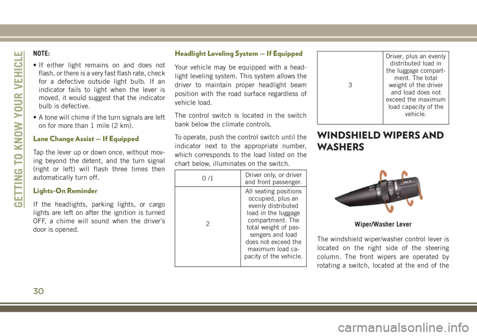
The windshield wiper/washer control lever is
located on the right side of the steering
column. The front wipers are operated by
rotating a switch, located at the end of the
Wiper/Washer Lever
GETTING TO KNOW YOUR VEHICLE
30
Page 60 of 276
• Check Gascap (refer to “Refueling The Ve-
hicle” in “Starting And Operating” for fur-
ther information)
• Oil Change Required (with a single chime)
• ECO (Fuel Saver Indicator) — if equipped
Gear Shift Indicator (GSI) — If Equipped
The Gear Shift Indicator (GSI) system is en-
abled on vehicles with a manual transmis-
sion, or when a vehicle with an automatic
transmission is in manual shift mode. The
GSI provides the driver with a visual indica-
tion when the recommended gear shift point
has been reached. This indication notifies
the driver that changing gear will allow a
reduction in fuel consumption. When the up
shift indicator is shown on the display, the
GSI is advising the driver to engage a higher
gear. When the down shift indicator is shown
on the display, the GSI is advising the driver
to engage a lower gear.
The GSI indicator remains illuminated until
the driver changes gear, or the driving condi-
tions return to a situation where changing gear
is not required to improve fuel consumption.
Oil Change Required
Your vehicle is equipped with an engine oil
change indicator system. The “Oil Change
Required” message will display in the instru-
ment cluster display for approximately
10 seconds after a single chime has sounded
to indicate the next scheduled oil change
interval. The engine oil change indicator sys-
tem is duty cycle based, which means the
engine oil change interval may fluctuate de-
pendent upon your personal driving style.
Unless reset, this message will continue to
display each time you turn the ignition switch
to the ON position. To turn off the message
temporarily, push and release theMENUbut-
ton. To reset the oil change indicator system
(after performing the scheduled mainte-
nance), perform the following procedure:
WARNING LIGHTS AND
MESSAGES
The warning/indicator lights will illuminate in
the instrument panel together with a dedi-
cated message and/or acoustic signal when
applicable. These indications are indicativeand precautionary and as such must not be
considered as exhaustive and/or alternative
to the information contained in the Owner’s
Manual, which you are advised to read care-
fully in all cases. Always refer to the informa-
tion in this chapter in the event of a failure
indication. All active telltales will display first
if applicable. The system check menu may
appear different based upon equipment op-
tions and current vehicle status. Some tell-
tales are optional and may not appear.
Red Warning Lights
— Air Bag Warning Light
This light indicates a fault with the air bag,
and will turn on for four to eight seconds as a
bulb check when the ignition is placed in the
ON/RUN or ACC/ON/RUN position. This light
will illuminate with a single chime when a
fault with the air bag has been detected, it
will stay on until the fault is cleared. If the
light is either not on during startup, stays on,
or turns on while driving, have the system
inspected at an authorized dealer as soon as
possible.
GETTING TO KNOW YOUR INSTRUMENT PANEL
58
Page 72 of 276
WARNING!
speed in turns, driving on very slippery
surfaces, or hydroplaning. The capabilities
of a BAS-equipped vehicle must never be
exploited in a reckless or dangerous man-
ner, which could jeopardize the user's
safety or the safety of others.
Hill Start Assist (HSA)
The HSA system is designed to mitigate roll
back from a complete stop while on an in-
cline. If the driver releases the brake while
stopped on an incline, HSA will continue to
hold the brake pressure for a short period. If
the driver does not apply the throttle before
this time expires, the system will release
brake pressure and the vehicle will roll down
the hill as normal.
The following conditions must be met in
order for HSA to activate:
• The feature must be enabled.
• The vehicle must be stopped.
• Park brake must be off.• Driver door must be closed.
• The vehicle must be on a sufficient grade.
• The gear selection must match vehicle up-
hill direction (i.e., vehicle facing uphill is in
forward gear; vehicle backing uphill is in
REVERSE gear).
• HSA will work in REVERSE gear and all
forward gears. The system will not activate
if the transmission is in PARK or NEU-
TRAL. For vehicles equipped with a manual
transmission, if the clutch is pressed, HSA
will remain active.
WARNING!
There may be situations where the Hill
Start Assist (HSA) will not activate and
slight rolling may occur, such as on minor
hills or with a loaded vehicle, or while
pulling a trailer. HSA is not a substitute for
active driving involvement. It is always the
driver’s responsibility to be attentive to
distance to other vehicles, people, and
objects, and most importantly brake op-
eration to ensure safe operation of the
vehicle under all road conditions. Your
WARNING!
complete attention is always required
while driving to maintain safe control of
your vehicle. Failure to follow these warn-
ings can result in a collision or serious
personal injury.
Disabling And Enabling HSA
This feature can be turned on or turned off.
To change the current setting using your
instrument cluster display, refer to “Instru-
ment Cluster Display” in “Getting To Know
Your Instrument Panel” for further informa-
tion.
For vehicles not equipped with an instrument
cluster display, perform the following steps:
1. Center the steering wheel (front wheels
pointing straight forward).
2. Shift the transmission into PARK.
3. Apply the parking brake.
4. Start the engine.
5. Rotate the steering wheel slightly more
than one-half turn to the left.
SAFETY
70
Page 77 of 276
WARNING!
• Trailer Sway Control (TSC) is disabled
when the ESC system is in the "Partial
Off" mode.
ESC Activation/Malfunction Indicator Light And
ESC OFF Indicator Light
The “ESC Activation/
Malfunction Indicator Light” in
the instrument cluster will come
on when the ignition is turned to
the ON mode. It should go out
with the engine running. If the “ESC
Activation/Malfunction Indicator Light”
comes on continuously with the engine run-
ning, a malfunction has been detected in the
ESC system. If this light remains on after
several ignition cycles, and the vehicle has
been driven several miles (kilometers) at
speeds greater than 30 mph (48 km/h), see
your authorized dealer as soon as possible to
have the problem diagnosed and corrected.
The “ESC Activation/Malfunction Indicator
Light” (located in the instrument cluster) starts
to flash as soon as the tires lose traction andthe ESC system becomes active. The “ESC
Activation/Malfunction Indicator Light” also
flashes when TCS is active. If the “ESC
Activation/Malfunction Indicator Light” begins
to flash during acceleration, ease up on the
accelerator and apply as little throttle as pos-
sible. Be sure to adapt your speed and driving
to the prevailing road conditions.
NOTE:
• The “ESC Activation/Malfunction Indicator
Light” and the “ESC OFF Indicator Light”
come on momentarily each time the igni-
tion is turned ON.
• Each time the ignition is turned ON, the
ESC system will be on even if it was turned
off previously.
• The ESC system will make buzzing or click-
ing sounds when it is active. This is normal;
the sounds will stop when ESC becomes
inactive following the maneuver that
caused the ESC activation.
The “ESC OFF Indicator Light”
indicates the customer has
elected to have the Electronic
Stability Control (ESC) in a re-
duced mode.
Electronic Roll Mitigation (ERM)
This system anticipates the potential for
wheel lift by monitoring the driver’s steering
wheel input and the speed of the vehicle.
When ERM determines that the rate of
change of the steering wheel angle and vehi-
cle’s speed are sufficient to potentially cause
wheel lift, it then applies the appropriate
brake and may also reduce engine power to
lessen the chance that wheel lift will occur.
ERM can only reduce the chance of wheel lift
occurring during severe or evasive driving
maneuvers; it cannot prevent wheel lift due to
other factors, such as road conditions, leav-
ing the roadway, or striking objects or other
vehicles.
NOTE:
ERM is disabled anytime the ESC is in “Full
Off” mode (if equipped). Refer to “Electronic
Stability Control (ESC)” in this section for a
complete explanation of the available ESC
modes.
75
Page 115 of 276
addition, inspect the exhaust system each
time the vehicle is raised for lubrication or oil
change. Replace as required.
Safety Checks You Should Make Inside
The Vehicle
Seat Belts
Inspect the seat belt system periodically,
checking for cuts, frays, and loose parts. Dam-
aged parts must be replaced immediately. Do
not disassemble or modify the system.
Front seat belt assemblies must be replaced
after a collision. Rear seat belt assemblies
must be replaced after a collision if they have
been damaged (i.e., bent retractor, torn web-
bing, etc.). If there is any question regarding
seat belt or retractor condition, replace the
seat belt.
Air Bag Warning Light
The Air Bag warning lightwill turn on for
four to eight seconds as a bulb check when the
ignition switch is first turned to ON/RUN. If the
light is either not on during starting, stays on, or
turns on while driving, have the system in-spected at an authorized dealer as soon as
possible. This light will illuminate with a single
chime when a fault with the Air Bag Warning
Light has been detected, it will stay on until the
fault is removed. If the light comes on intermit-
tently or remains on while driving, have an
authorized dealer service the vehicle immedi-
ately. Refer to “Occupant Restraint Systems” in
“Safety” for further information.
Defroster
Check operation by selecting the defrost
mode and place the blower control on high
speed. You should be able to feel the air
directed against the windshield. See your
authorized dealer for service if your defroster
is inoperable.
Floor Mat Safety Information
Always use floor mats designed to fit your
vehicle. Only use a floor mat that does not
interfere with the operation of the pedal as-
semblies. Only use a floor mat that is securely
attached using the floor mat fasteners so it
cannot slip out of position and interfere with
the pedal assemblies or impair safe operation
of your vehicle in other ways.
WARNING!
An improperly attached, damaged, folded,
or stacked floor mat, or damaged floor mat
fasteners may cause your floor mat to in-
terfere with the accelerator, brake, or
clutch pedals and cause a loss of vehicle
control. To prevent SERIOUS INJURY or
DEATH:
• ALWAYS securely attach
your floor
mat using the floor mat fasteners. DO
NOT install your floor mat upside down
or turn your floor mat over. Lightly pull to
confirm mat is secured using the floor
mat fasteners on a regular basis.
• ALWAYS REMOVE THE EXISTING
FLOOR MAT FROM THE VEHICLE
before installing any other floor mat.
NEVER install or stack an additional
floor mat on top of an existing floor mat.
• ONLY install floor mats designed to fit
your vehicle. NEVER install a floor mat
that cannot be properly attached and
secured to your vehicle. If a floor mat
needs to be replaced, only use a FCA
approved floor mat for the specific
make, model, and year of your vehicle.
113
Page 172 of 276
SCHEDULED SERVICING
Scheduled Servicing — Gasoline Engine
The scheduled services listed in this manual
must be done at the times or mileages speci-
fied to protect your vehicle warranty and
ensure the best vehicle performance and re-
liability. More frequent maintenance may be
needed for vehicles in severe operating con-
ditions, such as dusty areas and very short
trip driving. Inspection and service should
also be done anytime a malfunction is sus-
pected.
The oil change indicator system will remind
you that it is time to take your vehicle in for
scheduled maintenance.
On non-instrument cluster display equipped
vehicles, “CHANgE OIL” will flash in the
instrument cluster odometer and a single
chime will sound, indicating that an oil
change is necessary.The oil change indicator message will illumi-
nate approximately 7,000 miles
(11,200 km) after the most recent oil change
was performed. Have your vehicle serviced as
soon as possible, within 500 miles (800 km).
However, an earlier oil change at 4,500 miles
(7,500 km) may be required if the vehicle is
operated under “Severe Duty Conditions”
later in this section.
NOTE:
• The oil change indicator message will not
monitor the time since the last oil change.
Change your vehicle's oil if it has been
6 months since your last oil change even if
the oil change indicator message is NOT
illuminated.
• Change your engine oil more often if you
drive your vehicle off-road for an extended
period of time.
• Under no circumstances should oil change
intervals exceed 7,500 miles (12,000 km)
or 6 months, whichever comes first.
Your authorized dealer will reset the oil
change indicator message after completing
the scheduled oil change.Once A Month Or Before A Long Trip
• Check the engine oil level about five min-
utes after a fully warmed engine is shut off.
Checking the oil level while the vehicle is
on level ground will improve the accuracy of
the oil level reading. Add oil only when the
level is at or below the ADD or MIN mark.
• Check the windshield washer solvent and
add if required.
• Check tire pressure and look for unusual
wear or damage. Rotate tires at the first
sign of irregular wear, even if it occurs
before the oil indicator system turns on.
• Inspect the battery and clean and tighten
the terminals as required.
• Check the fluid levels of coolant reservoir,
automatic transmission, brake master cyl-
inder and power steering and fill as needed.
• Check all lights and other electrical items
for correct operation.
SERVICING AND MAINTENANCE
170
Page 173 of 276
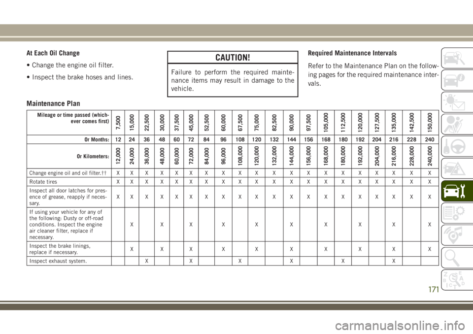
At Each Oil Change
• Change the engine oil filter.
• Inspect the brake hoses and lines.CAUTION!
Failure to perform the required mainte-
nance items may result in damage to the
vehicle.Required Maintenance Intervals
Refer to the Maintenance Plan on the follow-
ing pages for the required maintenance inter-
vals.
Maintenance Plan
Mileage or time passed (which-
ever comes first)
7,500
15,000
22,500
30,000
37,500
45,000
52,500
60,000
67,500
75,000
82,500
90,000
97,500
105,000
112,500
120,000
127,500
135,000
142,500
150,000
Or Months: 12 24 36 48 60 72 84 96 108 120 132 144 156 168 180 192 204 216 228 240
Or Kilometers:
12,000
24,000
36,000
48,000
60,000
72,000
84,000
96,000
108,000
120,000
132,000
144,000
156,000
168,000
180,000
192,000
204,000
216,000
228,000
240,000
Change engine oil and oil filter.††XXXXXXXXXX XXXXXXXX X X
Rotate tires X X X X X X X X X X X X X X X X X X X X
Inspect all door latches for pres-
ence of grease, reapply if neces-
sary.XXXXXXXXXX XXXXXXXX X X
If using your vehicle for any of
the following: Dusty or off-road
conditions. Inspect the engine
air cleaner filter, replace if
necessary.XXX X X X X X X X
Inspect the brake linings,
replace if necessary.XXX X X X X X X X
Inspect exhaust system. X X X X X X
171
Page 174 of 276
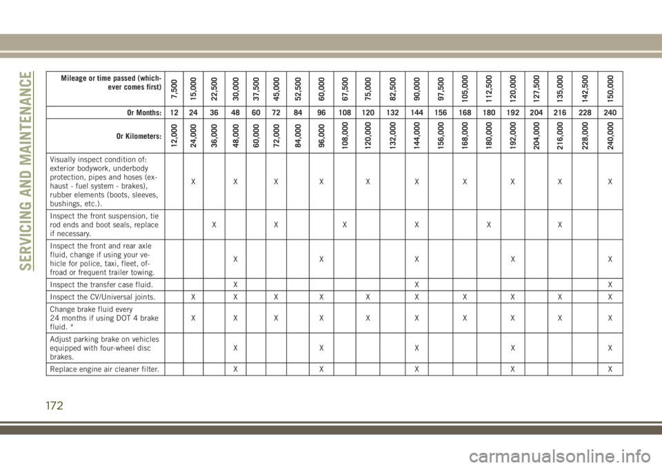
Mileage or time passed (which-
ever comes first)
7,500
15,000
22,500
30,000
37,500
45,000
52,500
60,000
67,500
75,000
82,500
90,000
97,500
105,000
112,500
120,000
127,500
135,000
142,500
150,000
Or Months: 12 24 36 48 60 72 84 96 108 120 132 144 156 168 180 192 204 216 228 240
Or Kilometers:
12,000
24,000
36,000
48,000
60,000
72,000
84,000
96,000
108,000
120,000
132,000
144,000
156,000
168,000
180,000
192,000
204,000
216,000
228,000
240,000
Visually inspect condition of:
exterior bodywork, underbody
protection, pipes and hoses (ex-
haust - fuel system - brakes),
rubber elements (boots, sleeves,
bushings, etc.).XXX X X X X X X X
Inspect the front suspension, tie
rod ends and boot seals, replace
if necessary.XXXXXX
Inspect the front and rear axle
fluid, change if using your ve-
hicle for police, taxi, fleet, of-
froad or frequent trailer towing.XX X X X
Inspect the transfer case fluid. X X X
Inspect the CV/Universal joints. X X X X X X X X X X
Change brake fluid every
24 months if using DOT 4 brake
fluid. *XXX X X X X X X X
Adjust parking brake on vehicles
equipped with four-wheel disc
brakes.XX X X X
Replace engine air cleaner filter. X X X X X
SERVICING AND MAINTENANCE
172