spare tire location JEEP WRANGLER 2020 Owner handbook (in English)
[x] Cancel search | Manufacturer: JEEP, Model Year: 2020, Model line: WRANGLER, Model: JEEP WRANGLER 2020Pages: 276, PDF Size: 4.47 MB
Page 81 of 276
• Driving on a significantly under-inflated tire
causes the tire to overheat and can lead to
tire failure. Under-inflation also reduces
fuel efficiency and tire tread life, and may
affect the vehicle’s handling and stopping
ability.
• The TPMS is not a substitute for proper tire
maintenance, and it is the driver’s respon-
sibility to maintain correct tire pressure,
even if under-inflation has not reached the
level to trigger illumination of the “Tire
Pressure Monitoring Telltale Light.”
• Seasonal temperature changes will affect
tire pressure, and the TPMS will monitor
the actual tire pressure in the tire.
Base System
The Tire Pressure Monitor System (TPMS)
uses wireless technology with wheel rim-
mounted electronic sensors to monitor tire
pressure levels. Sensors, mounted to each
wheel as part of the valve stem, transmit tire
pressure readings to the Receiver Module.NOTE:
It is particularly important for you to check
the tire pressure in all of your tires regularly
and to maintain the proper pressure.
The Tire Pressure Monitor System (TPMS)
consists of the following components:
• Receiver Module
• Four Tire Pressure Monitoring Sensors
• Tire Pressure Monitoring Telltale Light
A tire pressure monitoring sensor is located in
the spare wheel if the vehicle is equipped
with a matching full size spare wheel and tire
assembly. The matching full size spare tire
can be used in place of any of the four road
tires. A low spare tire will not cause the “Tire
Pressure Monitoring Telltale Light” to illumi-
nate or the chime to sound while stowed in
the spare location.
The “Tire Pressure Monitoring Tell-
tale Light” will illuminate in the in-
strument cluster, a “LOW TIRE
PRESSURE” message will display in the in-
strument cluster, and an audible chime will
be activated when one or more of the four
active road tire pressures are low. Should thisoccur, you should stop as soon as possible,
check the inflation pressure of each tire on
your vehicle, and inflate each tire to the
vehicle's recommended cold placard pres-
sure value. The system will automatically
update and the “Tire Pressure Monitoring
Telltale Light” will extinguish once the up-
dated tire pressures have been received. The
vehicle may need to be driven for up to
10 minutes above 15 mph (24 km/h) to
receive this information
The “Tire Pressure Monitoring Telltale Light”
will flash on and off for 75 seconds, and will
remain on solid when a system fault is de-
tected. The system fault will also sound a
chime. If the ignition key is cycled, this
sequence will repeat, providing the system
fault still exists. The “Tire Pressure Monitor-
ing Telltale Light” will turn off when the fault
condition no longer exists. A system fault can
occur by any of the following scenarios:
1. Jamming due to electronic devices or driv-
ing next to facilities emitting the same
Radio Frequencies as the TPM sensors.
79
Page 82 of 276
2. Installing some form of aftermarket win-
dow tinting that affects radio wave
signals.
3. Lots of snow or ice around the wheels or
wheel housings.
4. Using tire chains on the vehicle.
5. Using wheels/tires not equipped with
TPM sensors.
Vehicles not equipped with instrument clus-
ter display will inform the driver which tire(s)
are low but not provide actual tire pressure.
The low tire ISO telltale will illuminate along
with “LoTIrE” message displayed in the ODO
and then it will scroll to which tire location is
lower than the Placard Value.
Tire location will be displayed as follows:
LF =LeftFront
rF =rightFront
Lr =Leftrear
rr =rightrearNOTE:
• If your vehicle is equipped with a matching
full-size spare wheel and tire assembly, it
has a tire pressure monitoring sensor, and
can be monitored by the Tire Pressure
Monitoring System (TPMS) when swapped
with a low pressure road tire. In the event
that the matching full-size spare tire is
swapped with a low pressure road tire, the
next ignition key cycle will still show the
“Tire Pressure Monitoring Telltale Light” to
be ON, and a chime to sound. Driving the
vehicle for up to 10 minutes above 15 mph
(24 km/h) will turn OFF the “Tire Pressure
Monitoring Telltale Light” as long as none
of the road tires are below the low pressure
warning threshold.
• If your vehicle is not equipped with a
matching full-size spare wheel and tire as-
sembly, it does not have a tire pressure
monitoring sensor in the spare tire. The
TPMS will not be able to monitor the tire
pressure. If you install the spare tire in
place of a road tire that has a pressure
below the low-pressure warning limit, upon
the next ignition key cycle, a chime will
sound and the “Tire Pressure MonitoringTelltale Light” will turn ON. After driving
the vehicle for up to 10 minutes above
15 mph (24 km/h), the “Tire Pressure
Monitoring Telltale Light” will flash on and
off for 75 seconds and then remain on
solid. For each subsequent ignition key
cycle, a chime will sound and the “Tire
Pressure Monitoring Telltale Light” will
flash on and off for 75 seconds and then
remain on solid. Once you repair or replace
the original road tire, and reinstall it on the
vehicle in place of the spare tire, the TPMS
will update automatically and the “Tire
Pressure Monitoring Telltale Light” will
turn OFF, as long as no tire pressure is
below the low-pressure warning limit in any
of the four active road tires. The vehicle
may need to be driven for up to 10 minutes
above 15 mph (24 km/h) in order for the
TPMS to receive this information.
Premium System — If Equipped
The Tire Pressure Monitor System (TPMS)
uses wireless technology with wheel rim-
mounted electronic sensors to monitor tire
pressure levels. Sensors, mounted to each
wheel as part of the valve stem, transmit tire
pressure readings to the Receiver Module.
SAFETY
80
Page 151 of 276
Rear Tail, Stop, Turn Signal, And Backup
Lamp
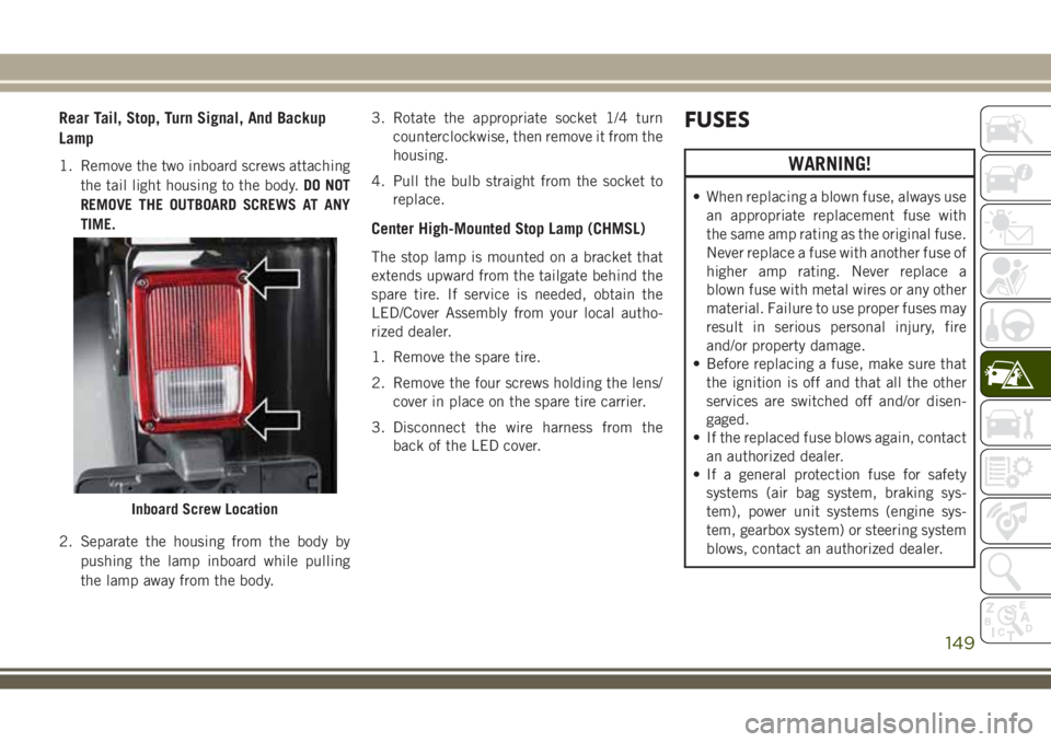
1. Remove the two inboard screws attaching
the tail light housing to the body.DO NOT
REMOVE THE OUTBOARD SCREWS AT ANY
TIME.
2. Separate the housing from the body by
pushing the lamp inboard while pulling
the lamp away from the body.3. Rotate the appropriate socket 1/4 turn
counterclockwise, then remove it from the
housing.
4. Pull the bulb straight from the socket to
replace.
Center High-Mounted Stop Lamp (CHMSL)
The stop lamp is mounted on a bracket that
extends upward from the tailgate behind the
spare tire. If service is needed, obtain the
LED/Cover Assembly from your local autho-
rized dealer.
1. Remove the spare tire.
2. Remove the four screws holding the lens/
cover in place on the spare tire carrier.
3. Disconnect the wire harness from the
back of the LED cover.
FUSES
WARNING!
• When replacing a blown fuse, always use
an appropriate replacement fuse with
the same amp rating as the original fuse.
Never replace a fuse with another fuse of
higher amp rating. Never replace a
blown fuse with metal wires or any other
material. Failure to use proper fuses may
result in serious personal injury, fire
and/or property damage.
• Before replacing a fuse, make sure that
the ignition is off and that all the other
services are switched off and/or disen-
gaged.
• If the replaced fuse blows again, contact
an authorized dealer.
• If a general protection fuse for safety
systems (air bag system, braking sys-
tem), power unit systems (engine sys-
tem, gearbox system) or steering system
blows, contact an authorized dealer.
Inboard Screw Location
149
Page 156 of 276
JACKING AND TIRE
CHANGING
WARNING!
• Do not attempt to change a tire on the
side of the vehicle close to moving traf-
fic. Pull far enough off the road to avoid
the danger of being hit when operating
the jack or changing the wheel.
• Being under a jacked-up vehicle is dan-
gerous. The vehicle could slip off the
jack and fall on you. You could be
crushed. Never put any part of your body
under a vehicle that is on a jack. If you
need to get under a raised vehicle, take
it to a service center where it can be
raised on a lift.
• Never start or run the engine while the
vehicle is on a jack.
• The jack is designed to be used as a tool
for changing tires only. The jack should
not be used to lift the vehicle for service
purposes. The vehicle should be jacked
on a firm level surface only. Avoid ice or
slippery areas.
Jack/Spare Tire Stowage
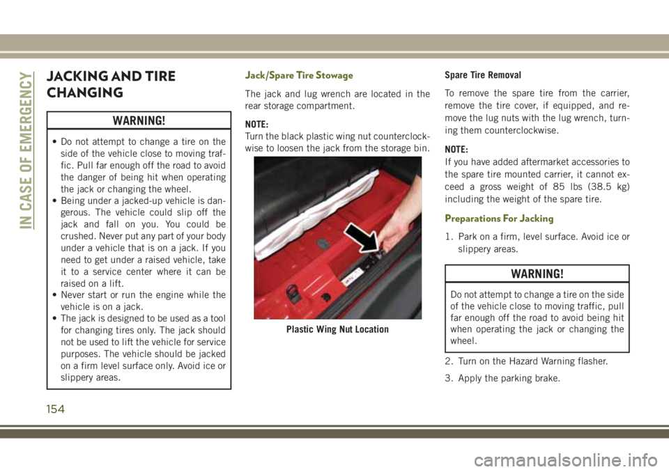
The jack and lug wrench are located in the
rear storage compartment.
NOTE:
Turn the black plastic wing nut counterclock-
wise to loosen the jack from the storage bin.Spare Tire Removal
To remove the spare tire from the carrier,
remove the tire cover, if equipped, and re-
move the lug nuts with the lug wrench, turn-
ing them counterclockwise.
NOTE:
If you have added aftermarket accessories to
the spare tire mounted carrier, it cannot ex-
ceed a gross weight of 85 lbs (38.5 kg)
including the weight of the spare tire.
Preparations For Jacking
1. Park on a firm, level surface. Avoid ice or
slippery areas.
WARNING!
Do not attempt to change a tire on the side
of the vehicle close to moving traffic, pull
far enough off the road to avoid being hit
when operating the jack or changing the
wheel.
2. Turn on the Hazard Warning flasher.
3. Apply the parking brake.
Plastic Wing Nut Location
IN CASE OF EMERGENCY
154
Page 158 of 276
CAUTION!
Do not attempt to raise the vehicle by
jacking on locations other than those indi-
cated.
1. Remove the spare tire, jack and tools from
the stored location.
2. Loosen (but do not remove) the wheel lug
nuts by turning them to the left one turn
while the wheel is still on the ground.
3. Assemble the jack and jacking tools. Con-
nect the jack handle driver to the exten-
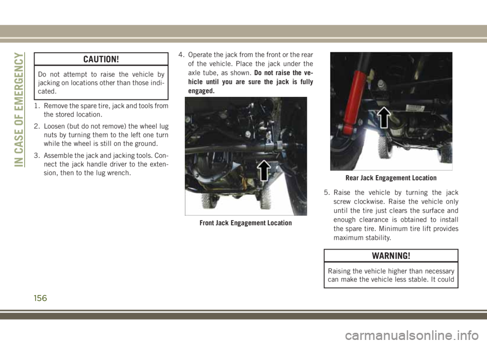
sion, then to the lug wrench.4. Operate the jack from the front or the rear
of the vehicle. Place the jack under the
axle tube, as shown.Do not raise the ve-
hicle until you are sure the jack is fully
engaged.
5. Raise the vehicle by turning the jack
screw clockwise. Raise the vehicle only
until the tire just clears the surface and
enough clearance is obtained to install
the spare tire. Minimum tire lift provides
maximum stability.
WARNING!
Raising the vehicle higher than necessary
can make the vehicle less stable. It could
Front Jack Engagement Location
Rear Jack Engagement Location
IN CASE OF EMERGENCY
156
Page 159 of 276
WARNING!
slip off the jack and hurt someone near it.
Raise the vehicle only enough to remove
the tire.
6. Remove the lug nuts and wheel.
7. Position the spare wheel/tire on the ve-
hicle and install the lug nuts with the
cone-shaped end toward the wheel.
Lightly tighten the lug nuts clockwise.
WARNING!
To avoid the risk of forcing the vehicle off
the jack, do not tighten the wheel nuts
fully until the vehicle has been lowered.
Failure to follow this warning may result in
serious injury.
8. Lower the vehicle by turning the jack
screw to the left, and remove the jack.9. Finish tightening the lug nuts. Push down
on the wrench while tightening for in-
creased leverage. Alternate nuts until
each nut has been tightened twice. Refer
to “Torque Specifications” in “Technical
Specifications” for correct lug nut torque.
10. Remove the jack assembly and wheel
blocks.
11. Secure the tire, jack, and tools in their
proper locations.
WARNING!
A loose tire or jack thrown forward in a
collision or hard stop, could endanger the
occupants of the vehicle. Always stow the
jack parts and the spare tire in the places
provided.
Declaration Of Conformance
1. The undersigned, Tony Fabiano, repre-
senting the manufacturer, herewith de-
clares that the machinery described below
fulfills all relevant provisions of:
• The EC-directive 2006/42/EC on
Machinery
2. Description of machinery.
a) Generic Denomination: Vehicle Jack
b) Function: Lifting Vehicle
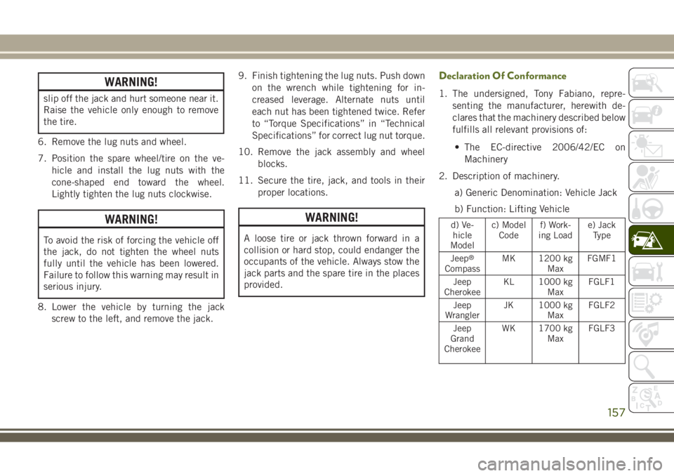
d) Ve-
hicle
Modelc) Model
Codef) Work-
ing Loade) Jack
Type
Jeep
®
CompassMK 1200 kg
MaxFGMF1
Jeep
CherokeeKL 1000 kg
MaxFGLF1
Jeep
WranglerJK 1000 kg
MaxFGLF2
Jeep
Grand
CherokeeWK 1700 kg
MaxFGLF3
157