warning lights JEEP WRANGLER 2020 Owner handbook (in English)
[x] Cancel search | Manufacturer: JEEP, Model Year: 2020, Model line: WRANGLER, Model: JEEP WRANGLER 2020Pages: 276, PDF Size: 4.47 MB
Page 17 of 276
• Ignition key removed from ignition
• Battery at an acceptable charge level
• System not disabled from previous remote
start event
• Vehicle security alarm not active
WARNING!
• Do not start or run an engine in a closed
garage or confined area. Exhaust gas
contains Carbon Monoxide (CO) which is
odorless and colorless. Carbon Monox-
ide is poisonous and can cause serious
injury or death when inhaled.
• Keep key fobs away from children. Op-
eration of the Remote Start System, win-
dows, door locks or other controls could
cause serious injury or death.
Remote Start Abort Message
The following messages will display in the
instrument cluster display if the vehicle fails to
remote start or exits remote start prematurely:
• Remote Start Aborted — Door Open
• Remote Start Aborted — Hood Open
• Remote Start Aborted — Fuel Low
• Remote Start Aborted — Swing Gate Open
• Remote Start Aborted — System Fault
The instrument cluster display message stays
active until the ignition is turned to the ON/
RUN position.
To Enter Remote Start
Push and release the remote start button on
the key fob twice within five seconds. The
vehicle doors will lock, the parking lights will
flash and the horn will chirp twice (if pro-
grammed). Then, the engine will start and the
vehicle will remain in the remote start mode
for a 15-minute cycle.NOTE:
• The park lamps will turn on and remain on
during remote start mode.
• For security, power window operation is
disabled when the vehicle is in the remote
start mode.
• The engine can be started two consecutive
times (two 15-minute cycles) with the key
fob. However, the ignition switch must be
cycled to the ON/RUN position before you
can repeat the start sequence for a third
cycle.
Remote start will also cancel if any of the
following occur:
• The engine stalls or RPM exceeds 2500.
• Any engine warning lamps come on.
• The hood is opened.
• The hazard switch is pushed.
• The transmission is moved out of PARK.
• The brake pedal is pushed.
15
Page 24 of 276
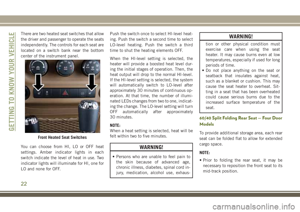
There are two heated seat switches that allow
the driver and passenger to operate the seats
independently. The controls for each seat are
located on a switch bank near the bottom
center of the instrument panel.
You can choose from HI, LO or OFF heat
settings. Amber indicator lights in each
switch indicate the level of heat in use. Two
indicator lights will illuminate for HI, one for
LO and none for OFF.Push the switch once to select HI-level heat-
ing. Push the switch a second time to select
LO-level heating. Push the switch a third
time to shut the heating elements OFF.
When the HI-level setting is selected, the
heater will provide a boosted heat level dur-
ing the initial stages of operation. Then, the
heat output will drop to the normal HI-level.
If the HI-level setting is selected, the system
will automatically switch to LO-level after
approximately 30 minutes of continuous op-
eration. At that time, the number of illumi-
nated LEDs changes from two to one, indicat-
ing the change. The LO-level setting will turn
OFF automatically after approximately
30 minutes.
NOTE:
When a heat setting is selected, heat will be
felt within two to five minutes.
WARNING!
• Persons who are unable to feel pain to
the skin because of advanced age,
chronic illness, diabetes, spinal cord in-
jury, medication, alcohol use, exhaus-
WARNING!
tion or other physical condition must
exercise care when using the seat
heater. It may cause burns even at low
temperatures, especially if used for long
periods of time.
• Do not place anything on the seat or
seatback that insulates against heat,
such as a blanket or cushion. This may
cause the seat heater to overheat. Sit-
ting in a seat that has been overheated
could cause serious burns due to the
increased surface temperature of the
seat.
60/40 Split Folding Rear Seat — Four Door
Models
To provide additional storage area, each rear
seat can be folded flat to allow for extended
cargo space.
NOTE:
• Prior to folding the rear seat, it may be
necessary to reposition the front seat to its
mid-track position.Front Heated Seat Switches
GETTING TO KNOW YOUR VEHICLE
22
Page 30 of 276
STEERING WHEEL
Tilt Steering Column
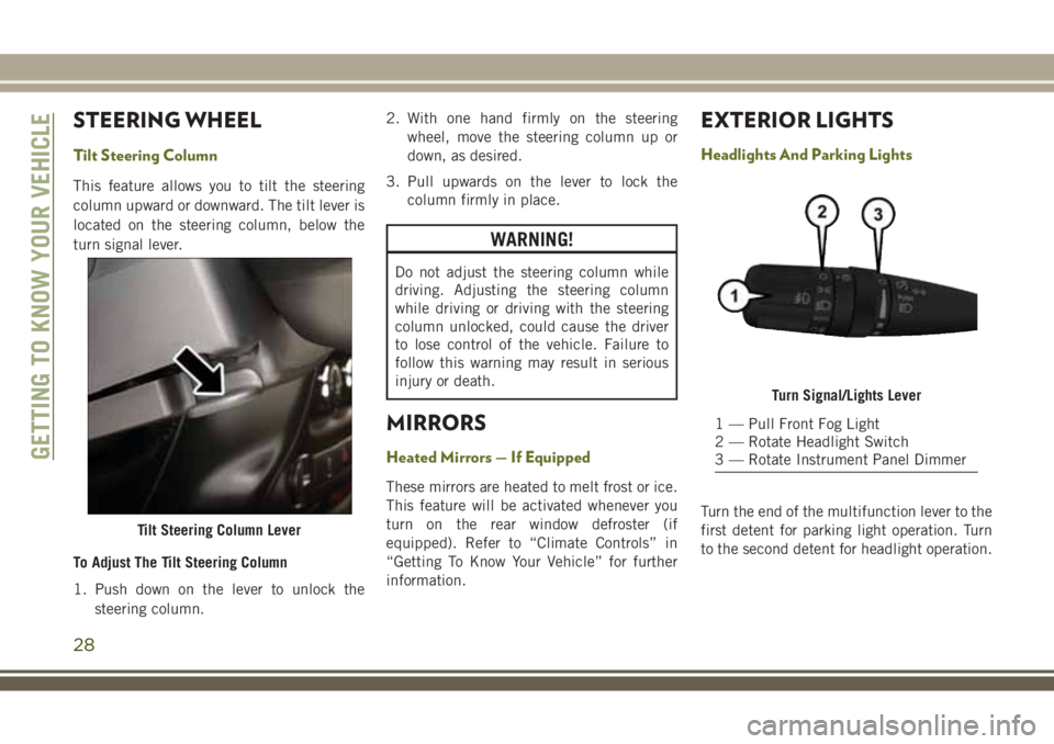
This feature allows you to tilt the steering
column upward or downward. The tilt lever is
located on the steering column, below the
turn signal lever.
To Adjust The Tilt Steering Column
1. Push down on the lever to unlock the
steering column.2. With one hand firmly on the steering
wheel, move the steering column up or
down, as desired.
3. Pull upwards on the lever to lock the
column firmly in place.
WARNING!
Do not adjust the steering column while
driving. Adjusting the steering column
while driving or driving with the steering
column unlocked, could cause the driver
to lose control of the vehicle. Failure to
follow this warning may result in serious
injury or death.
MIRRORS
Heated Mirrors — If Equipped
These mirrors are heated to melt frost or ice.
This feature will be activated whenever you
turn on the rear window defroster (if
equipped). Refer to “Climate Controls” in
“Getting To Know Your Vehicle” for further
information.
EXTERIOR LIGHTS
Headlights And Parking Lights
Turn the end of the multifunction lever to the
first detent for parking light operation. Turn
to the second detent for headlight operation.
Tilt Steering Column Lever
Turn Signal/Lights Lever
1 — Pull Front Fog Light
2 — Rotate Headlight Switch
3 — Rotate Instrument Panel Dimmer
GETTING TO KNOW YOUR VEHICLE
28
Page 57 of 276
GETTING TO KNOW YOUR INSTRUMENT PANEL
INSTRUMENT CLUSTER DISPLAY —
IF EQUIPPED................56
Instrument Cluster Display Location And
Controls.....................56
Instrument Cluster Display Messages . . .57
Gear Shift Indicator (GSI) — If
Equipped....................58
Oil Change Required.............58
WARNING LIGHTS AND MES-
SAGES ....................58
Red Warning Lights..............58
Yellow Warning Lights............61
Yellow Indicator Lights............63
Green Indicator Lights............64
White Indicator Lights............64
Blue Indicator Lights.............64
ONBOARD DIAGNOSTIC SYSTEM —
OBDII ....................64
Onboard Diagnostic System (OBD II)
Cybersecurity.................65
Loose Fuel Filler Cap Message.......65
GETTING TO KNOW YOUR INSTRUMENT PANEL
55
Page 60 of 276
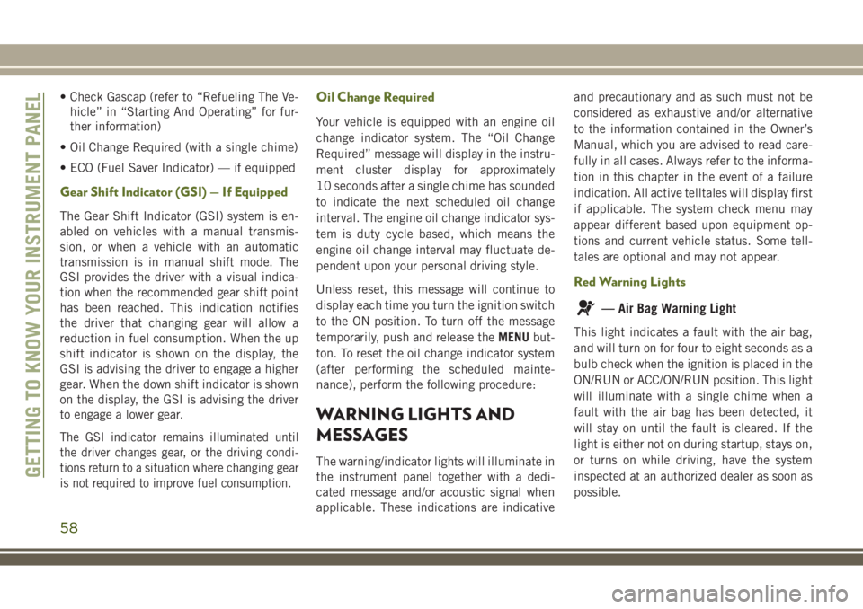
• Check Gascap (refer to “Refueling The Ve-
hicle” in “Starting And Operating” for fur-
ther information)
• Oil Change Required (with a single chime)
• ECO (Fuel Saver Indicator) — if equipped
Gear Shift Indicator (GSI) — If Equipped
The Gear Shift Indicator (GSI) system is en-
abled on vehicles with a manual transmis-
sion, or when a vehicle with an automatic
transmission is in manual shift mode. The
GSI provides the driver with a visual indica-
tion when the recommended gear shift point
has been reached. This indication notifies
the driver that changing gear will allow a
reduction in fuel consumption. When the up
shift indicator is shown on the display, the
GSI is advising the driver to engage a higher
gear. When the down shift indicator is shown
on the display, the GSI is advising the driver
to engage a lower gear.
The GSI indicator remains illuminated until
the driver changes gear, or the driving condi-
tions return to a situation where changing gear
is not required to improve fuel consumption.
Oil Change Required
Your vehicle is equipped with an engine oil
change indicator system. The “Oil Change
Required” message will display in the instru-
ment cluster display for approximately
10 seconds after a single chime has sounded
to indicate the next scheduled oil change
interval. The engine oil change indicator sys-
tem is duty cycle based, which means the
engine oil change interval may fluctuate de-
pendent upon your personal driving style.
Unless reset, this message will continue to
display each time you turn the ignition switch
to the ON position. To turn off the message
temporarily, push and release theMENUbut-
ton. To reset the oil change indicator system
(after performing the scheduled mainte-
nance), perform the following procedure:
WARNING LIGHTS AND
MESSAGES
The warning/indicator lights will illuminate in
the instrument panel together with a dedi-
cated message and/or acoustic signal when
applicable. These indications are indicativeand precautionary and as such must not be
considered as exhaustive and/or alternative
to the information contained in the Owner’s
Manual, which you are advised to read care-
fully in all cases. Always refer to the informa-
tion in this chapter in the event of a failure
indication. All active telltales will display first
if applicable. The system check menu may
appear different based upon equipment op-
tions and current vehicle status. Some tell-
tales are optional and may not appear.
Red Warning Lights
— Air Bag Warning Light
This light indicates a fault with the air bag,
and will turn on for four to eight seconds as a
bulb check when the ignition is placed in the
ON/RUN or ACC/ON/RUN position. This light
will illuminate with a single chime when a
fault with the air bag has been detected, it
will stay on until the fault is cleared. If the
light is either not on during startup, stays on,
or turns on while driving, have the system
inspected at an authorized dealer as soon as
possible.
GETTING TO KNOW YOUR INSTRUMENT PANEL
58
Page 63 of 276
remain on continuously and a chime will
sound. Refer to “Occupant Restraints Sys-
tems” in “Safety” for further information.
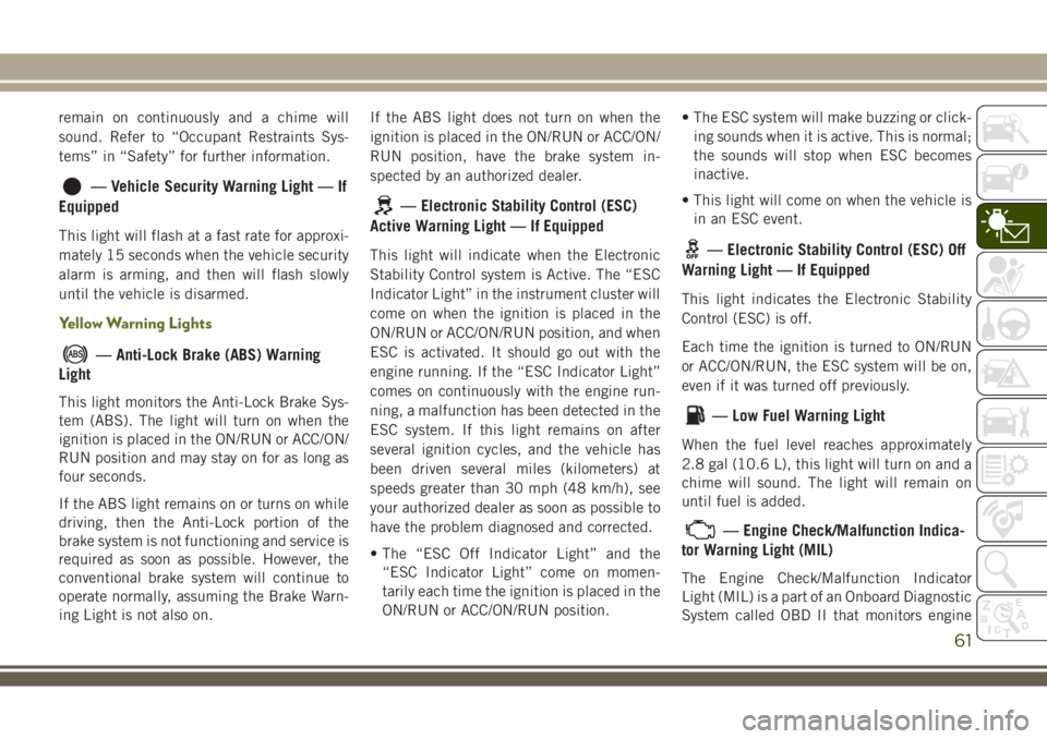
— Vehicle Security Warning Light — If
Equipped
This light will flash at a fast rate for approxi-
mately 15 seconds when the vehicle security
alarm is arming, and then will flash slowly
until the vehicle is disarmed.
Yellow Warning Lights
— Anti-Lock Brake (ABS) Warning
Light
This light monitors the Anti-Lock Brake Sys-
tem (ABS). The light will turn on when the
ignition is placed in the ON/RUN or ACC/ON/
RUN position and may stay on for as long as
four seconds.
If the ABS light remains on or turns on while
driving, then the Anti-Lock portion of the
brake system is not functioning and service is
required as soon as possible. However, the
conventional brake system will continue to
operate normally, assuming the Brake Warn-
ing Light is not also on.If the ABS light does not turn on when the
ignition is placed in the ON/RUN or ACC/ON/
RUN position, have the brake system in-
spected by an authorized dealer.
— Electronic Stability Control (ESC)
Active Warning Light — If Equipped
This light will indicate when the Electronic
Stability Control system is Active. The “ESC
Indicator Light” in the instrument cluster will
come on when the ignition is placed in the
ON/RUN or ACC/ON/RUN position, and when
ESC is activated. It should go out with the
engine running. If the “ESC Indicator Light”
comes on continuously with the engine run-
ning, a malfunction has been detected in the
ESC system. If this light remains on after
several ignition cycles, and the vehicle has
been driven several miles (kilometers) at
speeds greater than 30 mph (48 km/h), see
your authorized dealer as soon as possible to
have the problem diagnosed and corrected.
• The “ESC Off Indicator Light” and the
“ESC Indicator Light” come on momen-
tarily each time the ignition is placed in the
ON/RUN or ACC/ON/RUN position.• The ESC system will make buzzing or click-
ing sounds when it is active. This is normal;
the sounds will stop when ESC becomes
inactive.
• This light will come on when the vehicle is
in an ESC event.— Electronic Stability Control (ESC) Off
Warning Light — If Equipped
This light indicates the Electronic Stability
Control (ESC) is off.
Each time the ignition is turned to ON/RUN
or ACC/ON/RUN, the ESC system will be on,
even if it was turned off previously.
— Low Fuel Warning Light
When the fuel level reaches approximately
2.8 gal (10.6 L), this light will turn on and a
chime will sound. The light will remain on
until fuel is added.
— Engine Check/Malfunction Indica-
tor Warning Light (MIL)
The Engine Check/Malfunction Indicator
Light (MIL) is a part of an Onboard Diagnostic
System called OBD II that monitors engine
61
Page 65 of 276
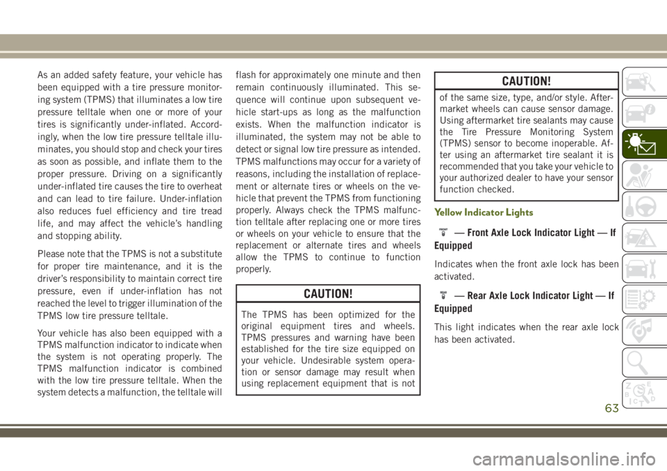
As an added safety feature, your vehicle has
been equipped with a tire pressure monitor-
ing system (TPMS) that illuminates a low tire
pressure telltale when one or more of your
tires is significantly under-inflated. Accord-
ingly, when the low tire pressure telltale illu-
minates, you should stop and check your tires
as soon as possible, and inflate them to the
proper pressure. Driving on a significantly
under-inflated tire causes the tire to overheat
and can lead to tire failure. Under-inflation
also reduces fuel efficiency and tire tread
life, and may affect the vehicle’s handling
and stopping ability.
Please note that the TPMS is not a substitute
for proper tire maintenance, and it is the
driver’s responsibility to maintain correct tire
pressure, even if under-inflation has not
reached the level to trigger illumination of the
TPMS low tire pressure telltale.
Your vehicle has also been equipped with a
TPMS malfunction indicator to indicate when
the system is not operating properly. The
TPMS malfunction indicator is combined
with the low tire pressure telltale. When the
system detects a malfunction, the telltale willflash for approximately one minute and then
remain continuously illuminated. This se-
quence will continue upon subsequent ve-
hicle start-ups as long as the malfunction
exists. When the malfunction indicator is
illuminated, the system may not be able to
detect or signal low tire pressure as intended.
TPMS malfunctions may occur for a variety of
reasons, including the installation of replace-
ment or alternate tires or wheels on the ve-
hicle that prevent the TPMS from functioning
properly. Always check the TPMS malfunc-
tion telltale after replacing one or more tires
or wheels on your vehicle to ensure that the
replacement or alternate tires and wheels
allow the TPMS to continue to function
properly.
CAUTION!
The TPMS has been optimized for the
original equipment tires and wheels.
TPMS pressures and warning have been
established for the tire size equipped on
your vehicle. Undesirable system opera-
tion or sensor damage may result when
using replacement equipment that is not
CAUTION!
of the same size, type, and/or style. After-
market wheels can cause sensor damage.
Using aftermarket tire sealants may cause
the Tire Pressure Monitoring System
(TPMS) sensor to become inoperable. Af-
ter using an aftermarket tire sealant it is
recommended that you take your vehicle to
your authorized dealer to have your sensor
function checked.
Yellow Indicator Lights
— Front Axle Lock Indicator Light — If
Equipped
Indicates when the front axle lock has been
activated.
— Rear Axle Lock Indicator Light — If
Equipped
This light indicates when the rear axle lock
has been activated.
63
Page 97 of 276
Seat belts are necessary for your protection in
all collisions, and also are needed to help
keep you in position, away from an inflating
air bag.
When the ORC detects a collision requiring
the front air bags, it signals the inflator units.
A large quantity of non-toxic gas is generated
to inflate the front air bags.
The steering wheel hub trim cover and the
upper passenger side of the instrument panel
separate and fold out of the way as the air
bags inflate to their full size. The front air
bags fully inflate in less time than it takes to
blink your eyes. The front air bags then
quickly deflate while helping to restrain the
driver and front passenger.
Knee Impact Bolsters
The Knee Impact Bolsters help protect the
knees of the driver and front passenger, and
position the front occupants for improved
interaction with the front air bags.
WARNING!
• Do not drill, cut, or tamper with the knee
impact bolsters in any way.
• Do not mount any accessories to the
knee impact bolsters such as alarm
lights, stereos, citizen band radios, etc.
Supplemental Side Air Bags
Supplemental Seat-Mounted Side Air Bags
(SABs) (if equipped)
Your vehicle may be equipped with Supple-
mental Seat-Mounted Side Air Bags (SABs).
If your vehicle is equipped with Supplemen-
tal Seat-Mounted Side Air Bags (SABs),
please refer to the information below.
Supplemental Seat-Mounted Side Air Bags
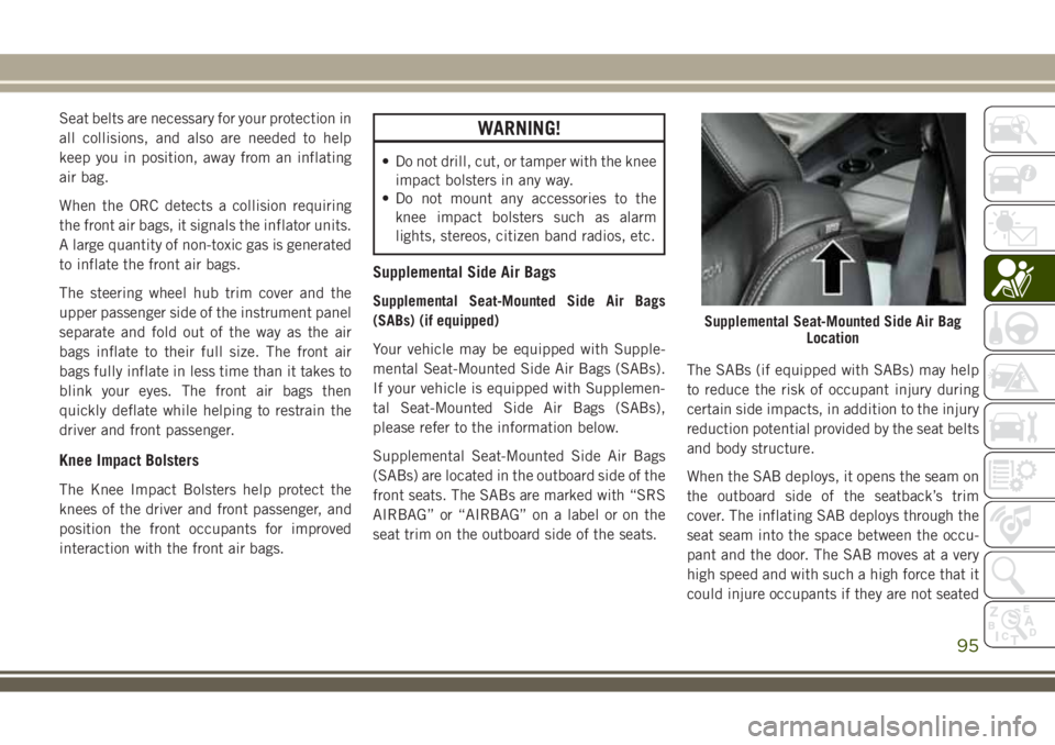
(SABs) are located in the outboard side of the
front seats. The SABs are marked with “SRS
AIRBAG” or “AIRBAG” on a label or on the
seat trim on the outboard side of the seats.The SABs (if equipped with SABs) may help
to reduce the risk of occupant injury during
certain side impacts, in addition to the injury
reduction potential provided by the seat belts
and body structure.
When the SAB deploys, it opens the seam on
the outboard side of the seatback’s trim
cover. The inflating SAB deploys through the
seat seam into the space between the occu-
pant and the door. The SAB moves at a very
high speed and with such a high force that it
could injure occupants if they are not seated
Supplemental Seat-Mounted Side Air Bag
Location
95
Page 100 of 276
NOTE:
• Air bag covers may not be obvious in the
interior trim, but they will open during air
bag deployment.
• After any collision, the vehicle should be
taken to an authorized dealer immediately.
Enhanced Accident Response System
In the event of an impact, if the communica-
tion network remains intact, and the power
remains intact, depending on the nature of
the event, the ORC will determine whether to
have the Enhanced Accident Response Sys-
tem perform the following functions:
• Cut off fuel to the engine.
• Flash hazard lights as long as the battery
has power or until the hazard light button is
pressed. The hazard lights can be deacti-
vated by pressing the hazard light button.
• Turn on the interior lights, which remain on
as long as the battery has power.
• Unlock the power door locks.
Enhanced Accident Response System Reset
Procedure
In order to reset the Enhanced Accident Re-
sponse System functions after an event, the
ignition switch must be changed from igni-
tion START or ON/RUN to ignition OFF. Care-
fully check the vehicle for fuel leaks in the
engine compartment and on the ground near
the engine compartment and fuel tank before
resetting the system and starting the engine.
Maintaining Your Air Bag System
WARNING!
• Modifications to any part of the air bag
system could cause it to fail when you
need it. You could be injured if the air
bag system is not there to protect you.
Do not modify the components or wiring,
including adding any kind of badges or
stickers to the steering wheel hub trim
cover or the upper right side of the
instrument panel. Do not modify the
front bumper, vehicle body structure, or
add aftermarket side steps or running
boards.
WARNING!
• It is dangerous to try to repair any part of
the air bag system yourself. Be sure to
tell anyone who works on your vehicle
that it has an air bag system.
• Do not attempt to modify any part of your
air bag system. The air bag may inflate
accidentally or may not function prop-
erly if modifications are made. Take your
vehicle to an authorized dealer for any
air bag system service. If your seat, in-
cluding your trim cover and cushion,
needs to be serviced in any way (includ-
ing removal or loosening/tightening of
seat attachment bolts), take the vehicle
to your authorized dealer. Only manufac-
turer approved seat accessories may be
used. If it is necessary to modify the air
bag system for persons with disabilities,
contact your authorized dealer.
Event Data Recorder (EDR)
This vehicle is equipped with an event data
recorder (EDR). The main purpose of an EDR
is to record, in certain crash or near crash-
like situations, such as an air bag deployment
SAFETY
98
Page 116 of 276
WARNING!
• ONLY use the driver’s side floor mat on
the driver’s side floor area. To check for
interference, with the vehicle properly
parked with the engine off, fully depress
the accelerator, the brake, and the
clutch pedal (if present) to check for
interference. If your floor mat interferes
with the operation of any pedal, or is not
secure to the floor, remove the floor mat
from the vehicle and place the floor mat
in your trunk.
• ONLY use the passenger’s side floor mat
on the passenger’s side floor area.
• ALWAYS make sure objects cannot fall or
slide into the driver’s side floor area
when the vehicle is moving. Objects can
become trapped under accelerator,
brake, or clutch pedals and could cause
a loss of vehicle control.
• NEVER place any objects under the floor
mat (e.g., towels, keys, etc.). These ob-
jects could change the position of the
floor mat and may cause interference
WARNING!
with the accelerator, brake, or clutch
pedals.
• If the vehicle carpet has been removed
and re-installed, always properly attach
carpet to the floor and check the floor
mat fasteners are secure to the vehicle
carpet. Fully depress each pedal to
check for interference with the accelera-
tor, brake, or clutch pedals then re-
install the floor mats.
• It is recommended to only use mild soap
and water to clean your floor mats. After
cleaning, always check your floor mat
has been properly installed and is se-
cured to your vehicle using the floor mat
fasteners by lightly pulling mat.
Periodic Safety Checks You Should Make
Outside The Vehicle
Tires
Examine tires for excessive tread wear and
uneven wear patterns. Check for stones,
nails, glass, or other objects lodged in thetread or sidewall. Inspect the tread for cuts
and cracks. Inspect sidewalls for cuts,
cracks, and bulges. Check the wheel nuts for
tightness. Check the tires (including spare)
for proper cold inflation pressure.
Lights
Have someone observe the operation of brake
lights and exterior lights while you work the
controls. Check turn signal and high beam
indicator lights on the instrument panel.
Door Latches
Check for proper closing, latching, and lock-
ing.
Fluid Leaks
Check area under vehicle after overnight
parking for fuel, coolant, oil, or other fluid
leaks. Also, if gasoline fumes are detected or
if fuel, or brake fluid leaks are suspected. The
cause should be located and corrected imme-
diately.
SAFETY
114