instrument panel JEEP WRANGLER 2021 Owner handbook (in English)
[x] Cancel search | Manufacturer: JEEP, Model Year: 2021, Model line: WRANGLER, Model: JEEP WRANGLER 2021Pages: 276, PDF Size: 4.47 MB
Page 56 of 276
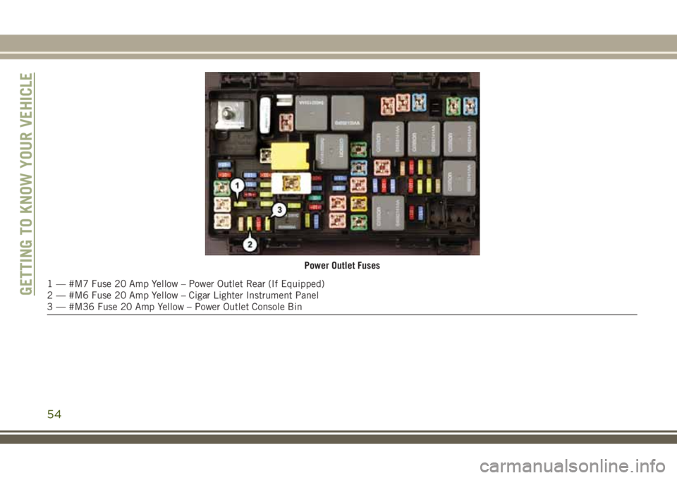
Power Outlet Fuses
1 — #M7 Fuse 20 Amp Yellow – Power Outlet Rear (If Equipped)
2 — #M6 Fuse 20 Amp Yellow – Cigar Lighter Instrument Panel
3 — #M36 Fuse 20 Amp Yellow – Power Outlet Console BinGETTING TO KNOW YOUR VEHICLE
54
Page 57 of 276
GETTING TO KNOW YOUR INSTRUMENT PANEL
INSTRUMENT CLUSTER DISPLAY —
IF EQUIPPED................56
Instrument Cluster Display Location And
Controls.....................56
Instrument Cluster Display Messages . . .57
Gear Shift Indicator (GSI) — If
Equipped....................58
Oil Change Required.............58
WARNING LIGHTS AND MES-
SAGES ....................58
Red Warning Lights..............58
Yellow Warning Lights............61
Yellow Indicator Lights............63
Green Indicator Lights............64
White Indicator Lights............64
Blue Indicator Lights.............64
ONBOARD DIAGNOSTIC SYSTEM —
OBDII ....................64
Onboard Diagnostic System (OBD II)
Cybersecurity.................65
Loose Fuel Filler Cap Message.......65
GETTING TO KNOW YOUR INSTRUMENT PANEL
55
Page 58 of 276
INSTRUMENT CLUSTER
DISPLAY — IF EQUIPPED
Your vehicle may be equipped with an instru-
ment cluster display, which offers useful in-
formation to the driver. With the ignition in
the STOP/OFF mode, opening/closing of a
door will activate the display for viewing, and
display the total miles, or kilometers, in the
odometer. Your instrument cluster display is
designed to display important information
about your vehicle’s systems and features.
Using a driver interactive display located on
the instrument panel, your instrument clus-
ter display can show you how systems are
working and give you warnings when they
aren’t. The steering wheel mounted controls
allow you to scroll through and enter the main
menus and submenus. You can access the
specific information you want and make se-
lections and adjustments.
Instrument Cluster Display Location And
Controls
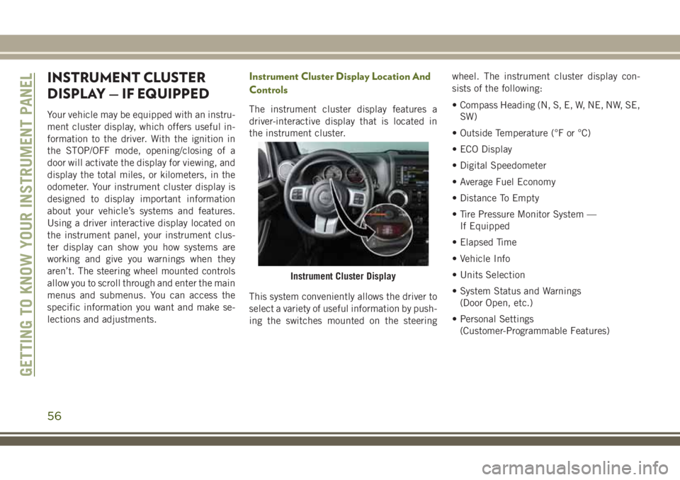
The instrument cluster display features a
driver-interactive display that is located in
the instrument cluster.
This system conveniently allows the driver to
select a variety of useful information by push-
ing the switches mounted on the steeringwheel. The instrument cluster display con-
sists of the following:
• Compass Heading (N, S, E, W, NE, NW, SE,
SW)
• Outside Temperature (°F or °C)
• ECO Display
• Digital Speedometer
• Average Fuel Economy
• Distance To Empty
• Tire Pressure Monitor System —
If Equipped
• Elapsed Time
• Vehicle Info
• Units Selection
• System Status and Warnings
(Door Open, etc.)
• Personal Settings
(Customer-Programmable Features)
Instrument Cluster Display
GETTING TO KNOW YOUR INSTRUMENT PANEL
56
Page 60 of 276
• Check Gascap (refer to “Refueling The Ve-
hicle” in “Starting And Operating” for fur-
ther information)
• Oil Change Required (with a single chime)
• ECO (Fuel Saver Indicator) — if equipped
Gear Shift Indicator (GSI) — If Equipped
The Gear Shift Indicator (GSI) system is en-
abled on vehicles with a manual transmis-
sion, or when a vehicle with an automatic
transmission is in manual shift mode. The
GSI provides the driver with a visual indica-
tion when the recommended gear shift point
has been reached. This indication notifies
the driver that changing gear will allow a
reduction in fuel consumption. When the up
shift indicator is shown on the display, the
GSI is advising the driver to engage a higher
gear. When the down shift indicator is shown
on the display, the GSI is advising the driver
to engage a lower gear.
The GSI indicator remains illuminated until
the driver changes gear, or the driving condi-
tions return to a situation where changing gear
is not required to improve fuel consumption.
Oil Change Required
Your vehicle is equipped with an engine oil
change indicator system. The “Oil Change
Required” message will display in the instru-
ment cluster display for approximately
10 seconds after a single chime has sounded
to indicate the next scheduled oil change
interval. The engine oil change indicator sys-
tem is duty cycle based, which means the
engine oil change interval may fluctuate de-
pendent upon your personal driving style.
Unless reset, this message will continue to
display each time you turn the ignition switch
to the ON position. To turn off the message
temporarily, push and release theMENUbut-
ton. To reset the oil change indicator system
(after performing the scheduled mainte-
nance), perform the following procedure:
WARNING LIGHTS AND
MESSAGES
The warning/indicator lights will illuminate in
the instrument panel together with a dedi-
cated message and/or acoustic signal when
applicable. These indications are indicativeand precautionary and as such must not be
considered as exhaustive and/or alternative
to the information contained in the Owner’s
Manual, which you are advised to read care-
fully in all cases. Always refer to the informa-
tion in this chapter in the event of a failure
indication. All active telltales will display first
if applicable. The system check menu may
appear different based upon equipment op-
tions and current vehicle status. Some tell-
tales are optional and may not appear.
Red Warning Lights
— Air Bag Warning Light
This light indicates a fault with the air bag,
and will turn on for four to eight seconds as a
bulb check when the ignition is placed in the
ON/RUN or ACC/ON/RUN position. This light
will illuminate with a single chime when a
fault with the air bag has been detected, it
will stay on until the fault is cleared. If the
light is either not on during startup, stays on,
or turns on while driving, have the system
inspected at an authorized dealer as soon as
possible.
GETTING TO KNOW YOUR INSTRUMENT PANEL
58
Page 62 of 276
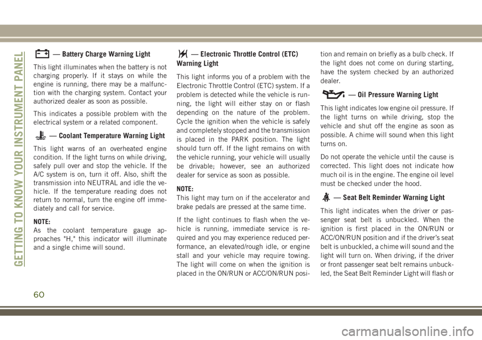
— Battery Charge Warning Light
This light illuminates when the battery is not
charging properly. If it stays on while the
engine is running, there may be a malfunc-
tion with the charging system. Contact your
authorized dealer as soon as possible.
This indicates a possible problem with the
electrical system or a related component.
— Coolant Temperature Warning Light
This light warns of an overheated engine
condition. If the light turns on while driving,
safely pull over and stop the vehicle. If the
A/C system is on, turn it off. Also, shift the
transmission into NEUTRAL and idle the ve-
hicle. If the temperature reading does not
return to normal, turn the engine off imme-
diately and call for service.
NOTE:
As the coolant temperature gauge ap-
proaches "H," this indicator will illuminate
and a single chime will sound.
— Electronic Throttle Control (ETC)
Warning Light
This light informs you of a problem with the
Electronic Throttle Control (ETC) system. If a
problem is detected while the vehicle is run-
ning, the light will either stay on or flash
depending on the nature of the problem.
Cycle the ignition when the vehicle is safely
and completely stopped and the transmission
is placed in the PARK position. The light
should turn off. If the light remains on with
the vehicle running, your vehicle will usually
be drivable; however, see an authorized
dealer for service as soon as possible.
NOTE:
This light may turn on if the accelerator and
brake pedals are pressed at the same time.
If the light continues to flash when the ve-
hicle is running, immediate service is re-
quired and you may experience reduced per-
formance, an elevated/rough idle, or engine
stall and your vehicle may require towing.
The light will come on when the ignition is
placed in the ON/RUN or ACC/ON/RUN posi-tion and remain on briefly as a bulb check. If
the light does not come on during starting,
have the system checked by an authorized
dealer.
— Oil Pressure Warning Light
This light indicates low engine oil pressure. If
the light turns on while driving, stop the
vehicle and shut off the engine as soon as
possible. A chime will sound when this light
turns on.
Do not operate the vehicle until the cause is
corrected. This light does not indicate how
much oil is in the engine. The engine oil level
must be checked under the hood.
— Seat Belt Reminder Warning Light
This light indicates when the driver or pas-
senger seat belt is unbuckled. When the
ignition is first placed in the ON/RUN or
ACC/ON/RUN position and if the driver’s seat
belt is unbuckled, a chime will sound and the
light will turn on. When driving, if the driver
or front passenger seat belt remains unbuck-
led, the Seat Belt Reminder Light will flash or
GETTING TO KNOW YOUR INSTRUMENT PANEL
60
Page 64 of 276
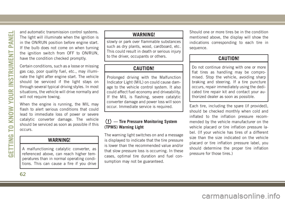
and automatic transmission control systems.
The light will illuminate when the ignition is
in the ON/RUN position before engine start.
If the bulb does not come on when turning
the ignition switch from OFF to ON/RUN,
have the condition checked promptly.
Certain conditions, such as a loose or missing
gas cap, poor quality fuel, etc., may illumi-
nate the light after engine start. The vehicle
should be serviced if the light stays on
through several typical driving styles. In most
situations, the vehicle will drive normally and
will not require towing.
When the engine is running, the MIL may
flash to alert serious conditions that could
lead to immediate loss of power or severe
catalytic converter damage. The vehicle
should be serviced as soon as possible if this
occurs.
WARNING!
A malfunctioning catalytic converter, as
referenced above, can reach higher tem-
peratures than in normal operating condi-
tions. This can cause a fire if you drive
WARNING!
slowly or park over flammable substances
such as dry plants, wood, cardboard, etc.
This could result in death or serious injury
to the driver, occupants or others.
CAUTION!
Prolonged driving with the Malfunction
Indicator Light (MIL) on could cause dam-
age to the vehicle control system. It also
could affect fuel economy and driveability.
If the MIL is flashing, severe catalytic
converter damage and power loss will soon
occur. Immediate service is required.
— Tire Pressure Monitoring System
(TPMS) Warning Light
The warning light switches on and a message
is displayed to indicate that the tire pressure
is lower than the recommended value and/or
that slow pressure loss is occurring. In these
cases, optimal tire duration and fuel con-
sumption may not be guaranteed.Should one or more tires be in the condition
mentioned above, the display will show the
indications corresponding to each tire in
sequence.
CAUTION!
Do not continue driving with one or more
flat tires as handling may be compro-
mised. Stop the vehicle, avoiding sharp
braking and steering. If a tire puncture
occurs, repair immediately using the dedi-
cated tire repair kit and contact your au-
thorized dealer as soon as possible.
Each tire, including the spare (if provided),
should be checked monthly when cold and
inflated to the inflation pressure recom-
mended by the vehicle manufacturer on the
vehicle placard or tire inflation pressure la-
bel. (If your vehicle has tires of a different
size than the size indicated on the vehicle
placard or tire inflation pressure label, you
should determine the proper tire inflation
pressure for those tires.)
GETTING TO KNOW YOUR INSTRUMENT PANEL
62
Page 66 of 276
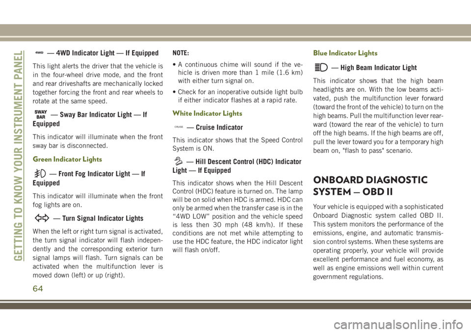
— 4WD Indicator Light — If Equipped
This light alerts the driver that the vehicle is
in the four-wheel drive mode, and the front
and rear driveshafts are mechanically locked
together forcing the front and rear wheels to
rotate at the same speed.
— Sway Bar Indicator Light — If
Equipped
This indicator will illuminate when the front
sway bar is disconnected.
Green Indicator Lights
— Front Fog Indicator Light — If
Equipped
This indicator will illuminate when the front
fog lights are on.
— Turn Signal Indicator Lights
When the left or right turn signal is activated,
the turn signal indicator will flash indepen-
dently and the corresponding exterior turn
signal lamps will flash. Turn signals can be
activated when the multifunction lever is
moved down (left) or up (right).NOTE:
• A continuous chime will sound if the ve-
hicle is driven more than 1 mile (1.6 km)
with either turn signal on.
• Check for an inoperative outside light bulb
if either indicator flashes at a rapid rate.
White Indicator Lights
CRUISE— Cruise Indicator
This indicator shows that the Speed Control
System is ON.
— Hill Descent Control (HDC) Indicator
Light — If Equipped
This indicator shows when the Hill Descent
Control (HDC) feature is turned on. The lamp
will be on solid when HDC is armed. HDC can
only be armed when the transfer case is in the
“4WD LOW” position and the vehicle speed
is less then 30 mph (48 km/h). If these
conditions are not met while attempting to
use the HDC feature, the HDC indicator light
will flash on/off.
Blue Indicator Lights
— High Beam Indicator Light
This indicator shows that the high beam
headlights are on. With the low beams acti-
vated, push the multifunction lever forward
(toward the front of the vehicle) to turn on the
high beams. Pull the multifunction lever rear-
ward (toward the rear of the vehicle) to turn
off the high beams. If the high beams are off,
pull the lever toward you for a temporary high
beam on, "flash to pass" scenario.
ONBOARD DIAGNOSTIC
SYSTEM — OBD II
Your vehicle is equipped with a sophisticated
Onboard Diagnostic system called OBD II.
This system monitors the performance of the
emissions, engine, and automatic transmis-
sion control systems. When these systems are
operating properly, your vehicle will provide
excellent performance and fuel economy, as
well as engine emissions well within current
government regulations.
GETTING TO KNOW YOUR INSTRUMENT PANEL
64
Page 72 of 276
WARNING!
speed in turns, driving on very slippery
surfaces, or hydroplaning. The capabilities
of a BAS-equipped vehicle must never be
exploited in a reckless or dangerous man-
ner, which could jeopardize the user's
safety or the safety of others.
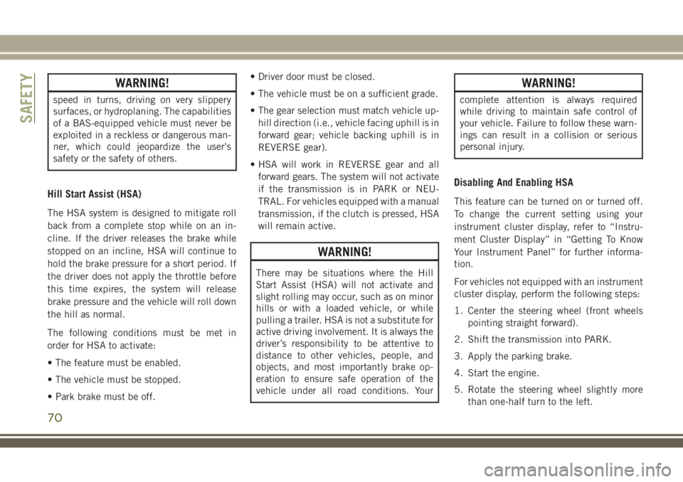
Hill Start Assist (HSA)
The HSA system is designed to mitigate roll
back from a complete stop while on an in-
cline. If the driver releases the brake while
stopped on an incline, HSA will continue to
hold the brake pressure for a short period. If
the driver does not apply the throttle before
this time expires, the system will release
brake pressure and the vehicle will roll down
the hill as normal.
The following conditions must be met in
order for HSA to activate:
• The feature must be enabled.
• The vehicle must be stopped.
• Park brake must be off.• Driver door must be closed.
• The vehicle must be on a sufficient grade.
• The gear selection must match vehicle up-
hill direction (i.e., vehicle facing uphill is in
forward gear; vehicle backing uphill is in
REVERSE gear).
• HSA will work in REVERSE gear and all
forward gears. The system will not activate
if the transmission is in PARK or NEU-
TRAL. For vehicles equipped with a manual
transmission, if the clutch is pressed, HSA
will remain active.
WARNING!
There may be situations where the Hill
Start Assist (HSA) will not activate and
slight rolling may occur, such as on minor
hills or with a loaded vehicle, or while
pulling a trailer. HSA is not a substitute for
active driving involvement. It is always the
driver’s responsibility to be attentive to
distance to other vehicles, people, and
objects, and most importantly brake op-
eration to ensure safe operation of the
vehicle under all road conditions. Your
WARNING!
complete attention is always required
while driving to maintain safe control of
your vehicle. Failure to follow these warn-
ings can result in a collision or serious
personal injury.
Disabling And Enabling HSA
This feature can be turned on or turned off.
To change the current setting using your
instrument cluster display, refer to “Instru-
ment Cluster Display” in “Getting To Know
Your Instrument Panel” for further informa-
tion.
For vehicles not equipped with an instrument
cluster display, perform the following steps:
1. Center the steering wheel (front wheels
pointing straight forward).
2. Shift the transmission into PARK.
3. Apply the parking brake.
4. Start the engine.
5. Rotate the steering wheel slightly more
than one-half turn to the left.
SAFETY
70
Page 83 of 276
NOTE:
It is particularly important, for you to regu-
larly check the tire pressure in all of your tires
and to maintain the proper pressure.
The Tire Pressure Monitor System (TPMS)
consists of the following components:
• Receiver Module
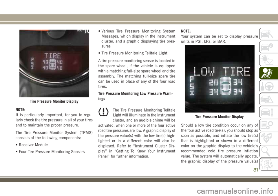
• Four Tire Pressure Monitoring Sensors• Various Tire Pressure Monitoring System
Messages, which display in the instrument
cluster, and a graphic displaying tire pres-
sures
• Tire Pressure Monitoring Telltale Light
A tire pressure monitoring sensor is located in
the spare wheel, if the vehicle is equipped
with a matching full-size spare wheel and tire
assembly. The matching full-size spare tire
can be used in place of any of the four road
tires.
Tire Pressure Monitoring Low Pressure Warn-
ingsThe Tire Pressure Monitoring Telltale
Light will illuminate in the instrument
cluster, and an audible chime will be
activated, when one or more of the four active
road tire pressures are low. A graphic display of
the pressure value(s) with the low tire(s) high-
lighted or in a different color will also be
displayed. Refer to “Instrument Cluster Dis-
play” in “Getting To Know Your Instrument
Panel” for further information.
NOTE:
Your system can be set to display pressure
units in PSI, kPa, or BAR.
Should a low tire condition occur on any of
the four active road tire(s), you should stop as
soon as possible, and inflate the low tire(s)
that is highlighted or shown in a different
color on the graphic display to the vehicle’s
recommended cold tire pressure inflation
value. The system will automatically update,
the graphic display of the pressure value(s)
Tire Pressure Monitor Display
Tire Pressure Monitor Display
81
Page 94 of 276
How To Disengage The Automatic Locking Mode
Unbuckle the combination lap/shoulder belt
and allow it to retract completely to disen-
gage the Automatic Locking Mode and acti-
vate the vehicle sensitive (emergency) lock-
ing mode.
WARNING!
• The seat belt assembly must be replaced
if the switchable Automatic Locking Re-
tractor (ALR) feature or any other seat
belt function is not working properly
when checked according to the proce-
dures in the Service Manual.
• Failure to replace the seat belt assembly
could increase the risk of injury in colli-
sions.
• Do not use the Automatic Locking Mode
to restrain occupants who are wearing
the seat belt or children who are using
booster seats. The locked mode is only
used to install rear-facing or forward-
facing child restraints that have a har-
ness for restraining the child.
Supplemental Restraint Systems (SRS)
Some of the safety features described in this
section may be standard equipment on some
models, or may be optional equipment on
others. If you are not sure, ask your autho-
rized dealer.
The air bag system must be ready to protect
you in a collision. The Occupant Restraint
Controller (ORC) monitors the internal cir-
cuits and interconnecting wiring associated
with the electrical Air Bag System Compo-
nents. Your vehicle may be equipped with the
following Air Bag System Components:
Air Bag System Components
•Occupant Restraint Controller (ORC)
•Air Bag Warning Light
•Steering Wheel and Column
•Instrument Panel
•Knee Impact Bolsters
•Driver and Front Passenger Air Bags
•Seat Belt Buckle Switch
•Supplemental Side Air Bags
•Front and Side Impact Sensors
•Seat Belt Pretensioners
Air Bag Warning Light
The ORC monitors the readiness of the
electronic parts of the air bag system when-
ever the ignition switch is in the START or
ON/RUN position. If the ignition switch is in
the OFF position or in the ACC position, the
air bag system is not on and the air bags will
not inflate.
The ORC contains a backup power supply
system that may deploy the air bag system
even if the battery loses power or it becomes
disconnected prior to deployment.
The ORC turns on the Air Bag Warning Light
in the instrument panel for approximately
four to eight seconds for a self-check when
the ignition switch is first in the ON/RUN
position. After the self-check, the Air Bag
Warning Light will turn off. If the ORC detects
a malfunction in any part of the system, it
turns on the Air Bag Warning Light, either
momentarily or continuously. A single chime
will sound to alert you if the light comes on
again after initial startup.
SAFETY
92