fuse JEEP WRANGLER 2021 Owner handbook (in English)
[x] Cancel search | Manufacturer: JEEP, Model Year: 2021, Model line: WRANGLER, Model: JEEP WRANGLER 2021Pages: 276, PDF Size: 4.47 MB
Page 55 of 276
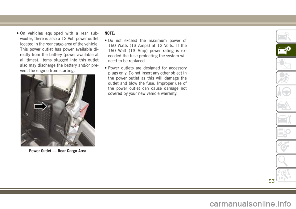
• On vehicles equipped with a rear sub-
woofer, there is also a 12 Volt power outlet
located in the rear cargo area of the vehicle.
This power outlet has power available di-
rectly from the battery (power available at
all times). Items plugged into this outlet
also may discharge the battery and/or pre-
vent the engine from starting.NOTE:
• Do not exceed the maximum power of
160 Watts (13 Amps) at 12 Volts. If the
160 Watt (13 Amp) power rating is ex-
ceeded the fuse protecting the system will
need to be replaced.
• Power outlets are designed for accessory
plugs only. Do not insert any other object in
the power outlet as this will damage the
outlet and blow the fuse. Improper use of
the power outlet can cause damage not
covered by your new vehicle warranty.
Power Outlet — Rear Cargo Area
53
Page 56 of 276
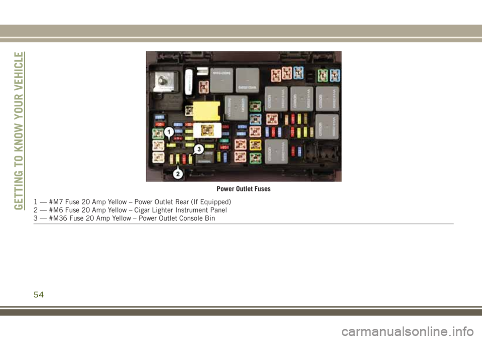
Power Outlet Fuses
1 — #M7 Fuse 20 Amp Yellow – Power Outlet Rear (If Equipped)
2 — #M6 Fuse 20 Amp Yellow – Cigar Lighter Instrument Panel
3 — #M36 Fuse 20 Amp Yellow – Power Outlet Console BinGETTING TO KNOW YOUR VEHICLE
54
Page 147 of 276
IN CASE OF EMERGENCY
HAZARD WARNING
FLASHERS................146
BULB REPLACEMENT........146
Replacement Bulbs............146
Bulb Replacement.............147
FUSES...................149
General Information.............150
Totally Integrated Power Module.....150
JACKING AND TIRE
CHANGING................154
Jack/Spare Tire Stowage..........154
Preparations For Jacking.........154
Jacking Instructions............155
Declaration Of Conformance.......157
Jack Usage Precautions..........160
JUMP STARTING............160
Preparations For Jump Start........161
Jump Starting Procedure..........162
IF YOUR ENGINE OVERHEATS . .163GEAR SELECTOR OVERRIDE . . .164
FREEING A STUCK VEHICLE . . .164
TOWING A DISABLED
VEHICLE..................165
Without The Ignition Key..........166
Four–Wheel Drive Models.........166
Tow Eye Usage................167
ENHANCED ACCIDENT RESPONSE
SYSTEM (EARS).............168
EVENT DATA RECORDER
(EDR)....................168
IN CASE OF EMERGENCY
145
Page 151 of 276
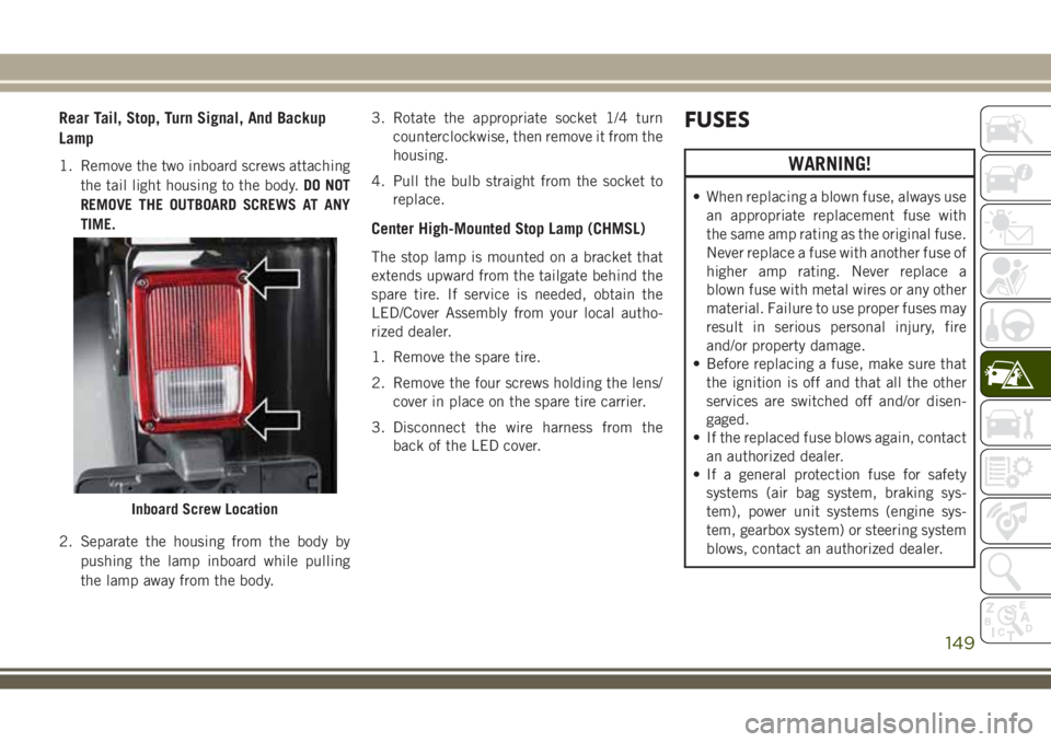
Rear Tail, Stop, Turn Signal, And Backup
Lamp
1. Remove the two inboard screws attaching
the tail light housing to the body.DO NOT
REMOVE THE OUTBOARD SCREWS AT ANY
TIME.
2. Separate the housing from the body by
pushing the lamp inboard while pulling
the lamp away from the body.3. Rotate the appropriate socket 1/4 turn
counterclockwise, then remove it from the
housing.
4. Pull the bulb straight from the socket to
replace.
Center High-Mounted Stop Lamp (CHMSL)
The stop lamp is mounted on a bracket that
extends upward from the tailgate behind the
spare tire. If service is needed, obtain the
LED/Cover Assembly from your local autho-
rized dealer.
1. Remove the spare tire.
2. Remove the four screws holding the lens/
cover in place on the spare tire carrier.
3. Disconnect the wire harness from the
back of the LED cover.
FUSES
WARNING!
• When replacing a blown fuse, always use
an appropriate replacement fuse with
the same amp rating as the original fuse.
Never replace a fuse with another fuse of
higher amp rating. Never replace a
blown fuse with metal wires or any other
material. Failure to use proper fuses may
result in serious personal injury, fire
and/or property damage.
• Before replacing a fuse, make sure that
the ignition is off and that all the other
services are switched off and/or disen-
gaged.
• If the replaced fuse blows again, contact
an authorized dealer.
• If a general protection fuse for safety
systems (air bag system, braking sys-
tem), power unit systems (engine sys-
tem, gearbox system) or steering system
blows, contact an authorized dealer.
Inboard Screw Location
149
Page 152 of 276
General Information
The fuses protect electrical systems against
excessive current.
When a device does not work, you must check
the fuse element inside the blade fuse for a
break/melt.
Also, please be aware that when using power
outlets for extended periods of time with the
engine off may result in vehicle battery dis-
charge.
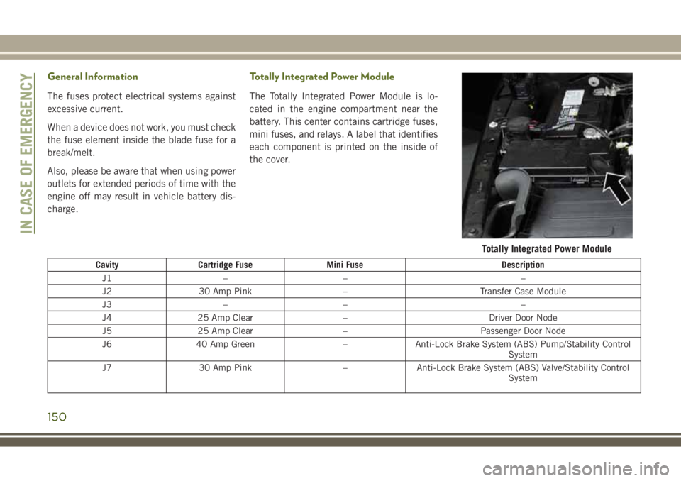
Totally Integrated Power Module
The Totally Integrated Power Module is lo-
cated in the engine compartment near the
battery. This center contains cartridge fuses,
mini fuses, and relays. A label that identifies
each component is printed on the inside of
the cover.
Cavity Cartridge Fuse Mini Fuse Description
J1 – – –
J2 30 Amp Pink – Transfer Case Module
J3 – – –
J4 25 Amp Clear – Driver Door Node
J5 25 Amp Clear – Passenger Door Node
J6 40 Amp Green – Anti-Lock Brake System (ABS) Pump/Stability Control
System
J7 30 Amp Pink – Anti-Lock Brake System (ABS) Valve/Stability Control
System
Totally Integrated Power Module
IN CASE OF EMERGENCY
150
Page 153 of 276
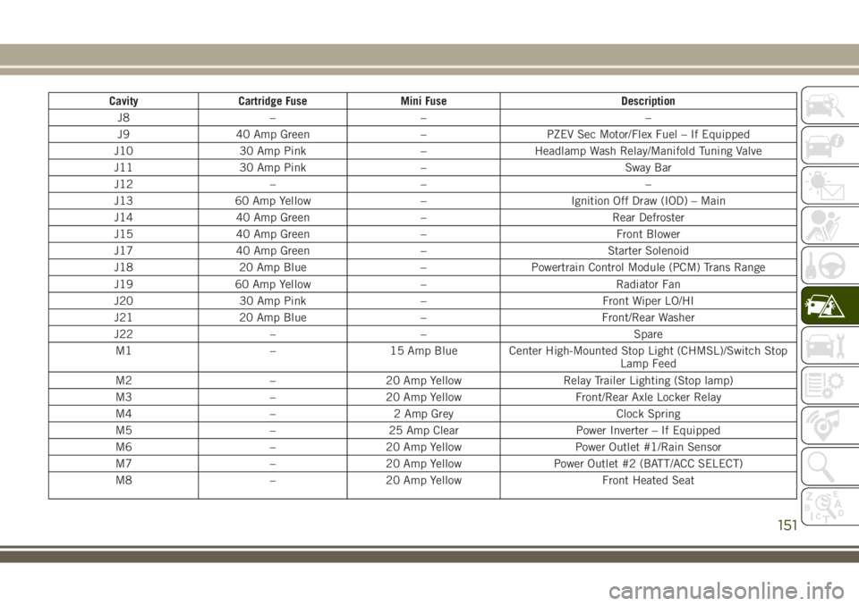
Cavity Cartridge Fuse Mini Fuse Description
J8 – – –
J9 40 Amp Green – PZEV Sec Motor/Flex Fuel – If Equipped
J10 30 Amp Pink – Headlamp Wash Relay/Manifold Tuning Valve
J11 30 Amp Pink – Sway Bar
J12 – – –
J13 60 Amp Yellow – Ignition Off Draw (IOD) – Main
J14 40 Amp Green – Rear Defroster
J15 40 Amp Green – Front Blower
J17 40 Amp Green – Starter Solenoid
J18 20 Amp Blue – Powertrain Control Module (PCM) Trans Range
J19 60 Amp Yellow – Radiator Fan
J20 30 Amp Pink – Front Wiper LO/HI
J21 20 Amp Blue – Front/Rear Washer
J22 – – Spare
M1 – 15 Amp Blue Center High-Mounted Stop Light (CHMSL)/Switch Stop
Lamp Feed
M2 – 20 Amp Yellow Relay Trailer Lighting (Stop lamp)
M3 – 20 Amp Yellow Front/Rear Axle Locker Relay
M4 – 2 Amp Grey Clock Spring
M5 – 25 Amp Clear Power Inverter – If Equipped
M6 – 20 Amp Yellow Power Outlet #1/Rain Sensor
M7 – 20 Amp Yellow Power Outlet #2 (BATT/ACC SELECT)
M8 – 20 Amp Yellow Front Heated Seat
151
Page 154 of 276
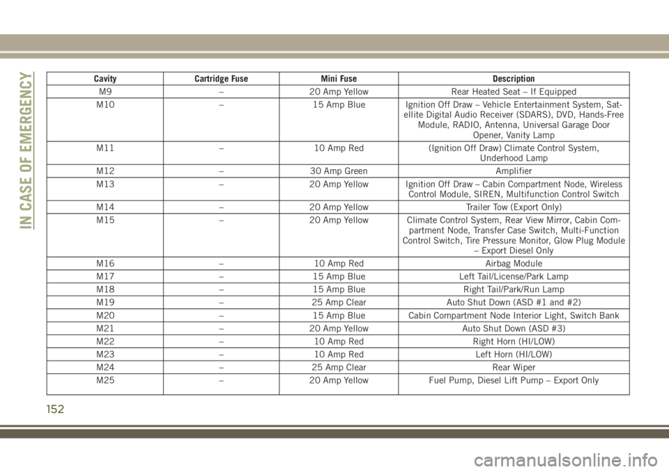
Cavity Cartridge Fuse Mini Fuse Description
M9 – 20 Amp Yellow Rear Heated Seat – If Equipped
M10 – 15 Amp Blue Ignition Off Draw – Vehicle Entertainment System, Sat-
ellite Digital Audio Receiver (SDARS), DVD, Hands-Free
Module, RADIO, Antenna, Universal Garage Door
Opener, Vanity Lamp
M11 – 10 Amp Red (Ignition Off Draw) Climate Control System,
Underhood Lamp
M12 – 30 Amp Green Amplifier
M13 – 20 Amp Yellow Ignition Off Draw – Cabin Compartment Node, Wireless
Control Module, SIREN, Multifunction Control Switch
M14 – 20 Amp Yellow Trailer Tow (Export Only)
M15 – 20 Amp Yellow Climate Control System, Rear View Mirror, Cabin Com-
partment Node, Transfer Case Switch, Multi-Function
Control Switch, Tire Pressure Monitor, Glow Plug Module
– Export Diesel Only
M16 – 10 Amp Red Airbag Module
M17 – 15 Amp Blue Left Tail/License/Park Lamp
M18 – 15 Amp Blue Right Tail/Park/Run Lamp
M19 – 25 Amp Clear Auto Shut Down (ASD #1 and #2)
M20 – 15 Amp Blue Cabin Compartment Node Interior Light, Switch Bank
M21 – 20 Amp Yellow Auto Shut Down (ASD #3)
M22 – 10 Amp Red Right Horn (HI/LOW)
M23 – 10 Amp Red Left Horn (HI/LOW)
M24 – 25 Amp Clear Rear Wiper
M25 – 20 Amp Yellow Fuel Pump, Diesel Lift Pump – Export Only
IN CASE OF EMERGENCY
152
Page 155 of 276
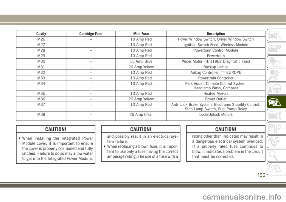
Cavity Cartridge Fuse Mini Fuse Description
M26 – 10 Amp Red Power Window Switch, Driver Window Switch
M27 – 10 Amp Red Ignition Switch Feed, Wireless Module
M28 – 10 Amp Red Powertrain Control Module
M29 – 10 Amp Red Powertrain
M30 – 15 Amp Blue Wiper Motor Frt, J1962 Diagnostic Feed
M31 – 20 Amp Yellow Backup Lamps
M32 – 10 Amp Red Airbag Controller, TT EUROPE
M33 – 10 Amp Red Powertrain Controller
M34 – 10 Amp Red Park Assist, Climate Control System,
Headlamp Wash, Compass
M35 – 10 Amp Red Heated Mirrors
M36 – 20 Amp Yellow Power Outlet
M37 – 10 Amp Red Anti-Lock Brake System, Electronic Stability Control,
Stop Lamp Switch, Fuel Pump Relay
M38 – 25 Amp Clear Lock/Unlock Motors
CAUTION!
• When installing the Integrated Power
Module cover, it is important to ensure
the cover is properly positioned and fully
latched. Failure to do so may allow water
to get into the Integrated Power Module,
CAUTION!
and possibly result in an electrical sys-
tem failure.
• When replacing a blown fuse, it is impor-
tant to use only a fuse having the correct
amperage rating. The use of a fuse with a
CAUTION!
rating other than indicated may result in
a dangerous electrical system overload.
If a properly rated fuse continues to
blow, it indicates a problem in the circuit
that must be corrected.
153
Page 182 of 276
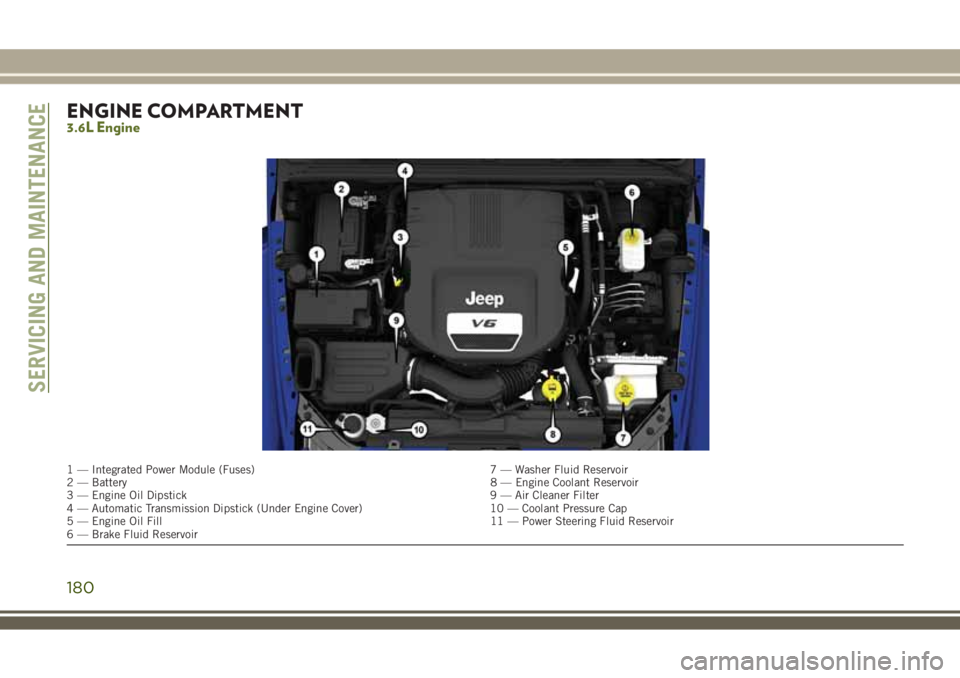
ENGINE COMPARTMENT3.6L Engine
1 — Integrated Power Module (Fuses) 7 — Washer Fluid Reservoir
2 — Battery8 — Engine Coolant Reservoir
3 — Engine Oil Dipstick 9 — Air Cleaner Filter
4 — Automatic Transmission Dipstick (Under Engine Cover) 10 — Coolant Pressure Cap
5 — Engine Oil Fill 11 — Power Steering Fluid Reservoir
6 — Brake Fluid Reservoir
SERVICING AND MAINTENANCE
180
Page 183 of 276
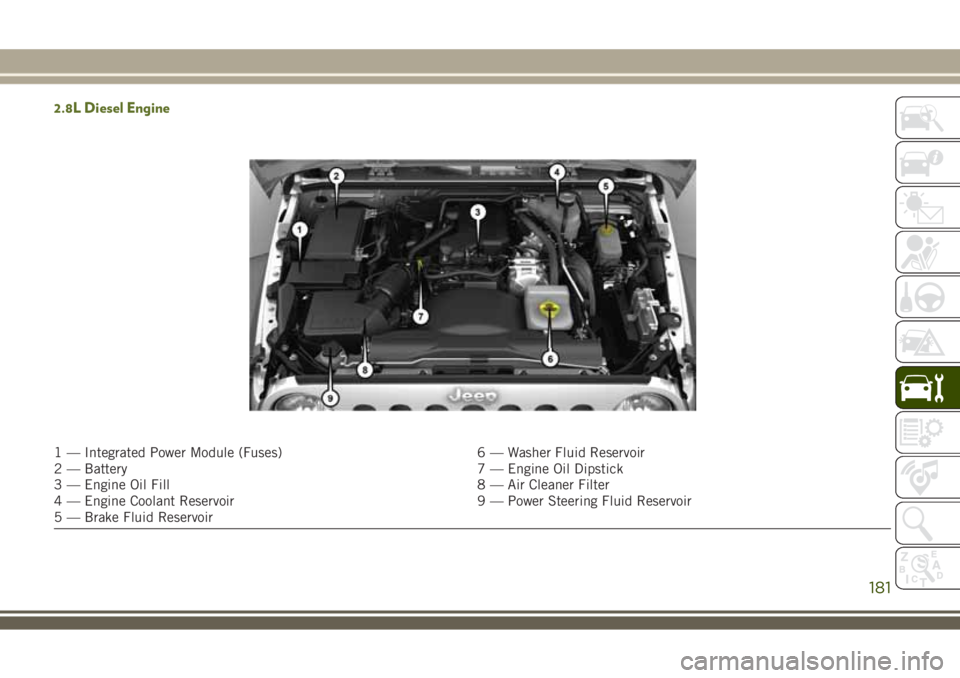
2.8L Diesel Engine
1 — Integrated Power Module (Fuses) 6 — Washer Fluid Reservoir
2 — Battery 7 — Engine Oil Dipstick
3 — Engine Oil Fill 8 — Air Cleaner Filter
4 — Engine Coolant Reservoir 9 — Power Steering Fluid Reservoir
5 — Brake Fluid Reservoir
181