window JEEP WRANGLER 2023 Owners Manual
[x] Cancel search | Manufacturer: JEEP, Model Year: 2023, Model line: WRANGLER, Model: JEEP WRANGLER 2023Pages: 396, PDF Size: 25.15 MB
Page 4 of 396
2
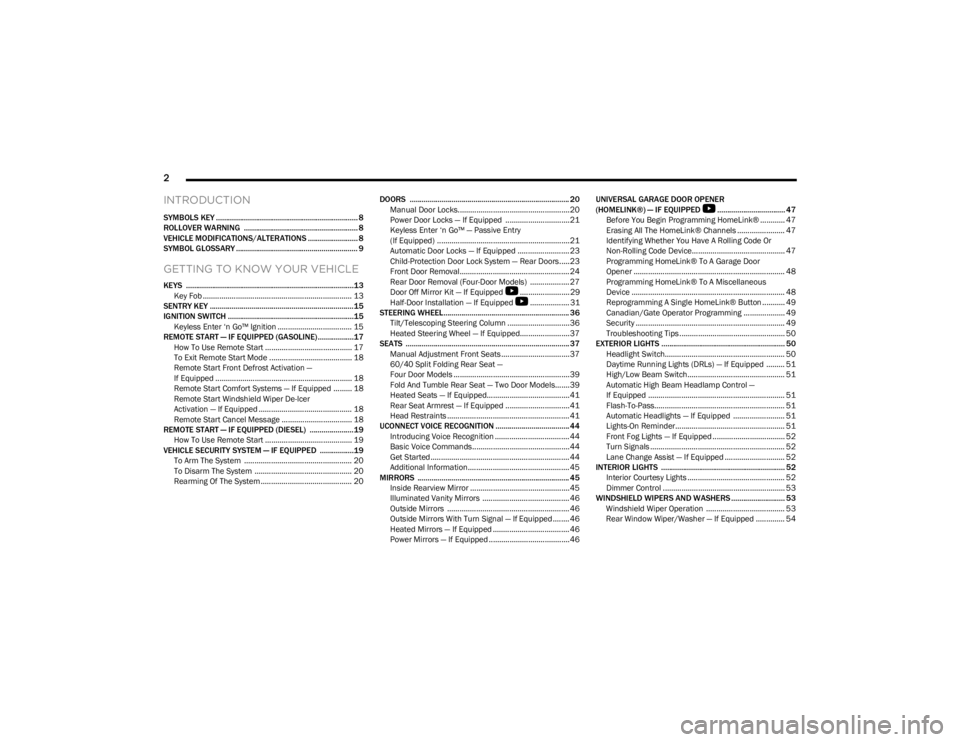
INTRODUCTION
SYMBOLS KEY ....................................................................... 8
ROLLOVER WARNING ......................................................... 8
VEHICLE MODIFICATIONS/ALTERATIONS ......................... 8
SYMBOL GLOSSARY ............................................................. 9
GETTING TO KNOW YOUR VEHICLE
KEYS ....................................................................................13
Key Fob ........................................................................ 13
SENTRY KEY ........................................................................15
IGNITION SWITCH ...............................................................15 Keyless Enter ‘n Go™ Ignition .................................... 15
REMOTE START — IF EQUIPPED (GASOLINE)..................17 How To Use Remote Start .......................................... 17
To Exit Remote Start Mode ........................................ 18
Remote Start Front Defrost Activation —
If Equipped .................................................................. 18
Remote Start Comfort Systems — If Equipped ......... 18
Remote Start Windshield Wiper De-Icer
Activation — If Equipped ............................................. 18
Remote Start Cancel Message .................................. 18
REMOTE START — IF EQUIPPED (DIESEL) ......................19 How To Use Remote Start .......................................... 19
VEHICLE SECURITY SYSTEM — IF EQUIPPED .................19 To Arm The System .................................................... 20
To Disarm The System ............................................... 20
Rearming Of The System ............................................ 20 DOORS ................................................................................ 20
Manual Door Locks......................................................20
Power Door Locks — If Equipped ............................... 21
Keyless Enter ‘n Go™ — Passive Entry
(If Equipped) ................................................................ 21
Automatic Door Locks — If Equipped ......................... 23
Child-Protection Door Lock System — Rear Doors.....23
Front Door Removal..................................................... 24
Rear Door Removal (Four-Door Models) ................... 27
Door Off Mirror Kit — If Equipped
S
........................ 29
Half-Door Installation — If Equipped
S
................... 31
STEERING WHEEL............................................................... 36 Tilt/Telescoping Steering Column ..............................36
Heated Steering Wheel — If Equipped........................ 37
SEATS .................................................................................. 37 Manual Adjustment Front Seats ................................. 37
60/40 Split Folding Rear Seat —
Four Door Models ........................................................ 39
Fold And Tumble Rear Seat — Two Door Models....... 39
Heated Seats — If Equipped........................................ 41
Rear Seat Armrest — If Equipped ............................... 41
Head Restraints ........................................................... 41
UCONNECT VOICE RECOGNITION ..................................... 44 Introducing Voice Recognition .................................... 44
Basic Voice Commands............................................... 44
Get Started ................................................................... 44
Additional Information................................................. 45
MIRRORS ............................................................................ 45 Inside Rearview Mirror ................................................ 45
Illuminated Vanity Mirrors .......................................... 46
Outside Mirrors ........................................................... 46
Outside Mirrors With Turn Signal — If Equipped ........ 46
Heated Mirrors — If Equipped ..................................... 46
Power Mirrors — If Equipped ....................................... 46 UNIVERSAL GARAGE DOOR OPENER
(HOMELINK®) — IF EQUIPPED
S
.................................. 47
Before You Begin Programming HomeLink® ............ 47
Erasing All The HomeLink® Channels ....................... 47
Identifying Whether You Have A Rolling Code Or
Non-Rolling Code Device............................................. 47
Programming HomeLink® To A Garage Door
Opener ......................................................................... 48
Programming HomeLink® To A Miscellaneous
Device .......................................................................... 48
Reprogramming A Single HomeLink® Button ........... 49
Canadian/Gate Operator Programming .................... 49
Security ........................................................................ 49
Troubleshooting Tips ................................................... 50
EXTERIOR LIGHTS .............................................................. 50 Headlight Switch.......................................................... 50
Daytime Running Lights (DRLs) — If Equipped ......... 51
High/Low Beam Switch............................................... 51
Automatic High Beam Headlamp Control —
If Equipped .................................................................. 51
Flash-To-Pass............................................................... 51
Automatic Headlights — If Equipped ......................... 51
Lights-On Reminder..................................................... 51
Front Fog Lights — If Equipped ................................... 52
Turn Signals ................................................................. 52
Lane Change Assist — If Equipped ............................. 52
INTERIOR LIGHTS .............................................................. 52 Interior Courtesy Lights ............................................... 52
Dimmer Control ........................................................... 53
WINDSHIELD WIPERS AND WASHERS ........................... 53 Windshield Wiper Operation ...................................... 53
Rear Window Wiper/Washer — If Equipped .............. 54
23_JL_OM_EN_USC_t.book Page 2
Page 5 of 396
3
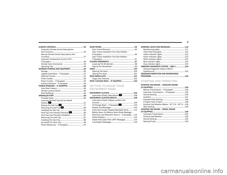
CLIMATE CONTROLS ..........................................................54Automatic Climate Control Descriptions
And Functions.............................................................. 54
Manual Climate Control Descriptions And
Functions ..................................................................... 57
Automatic Temperature Control (ATC) —
If Equipped .................................................................. 59
Climate Voice Commands ......................................... 59
Operating Tips ............................................................ 59
INTERIOR STORAGE AND EQUIPMENT ............................60 Storage ........................................................................ 60
Lighted Cupholders — If Equipped ............................. 61
USB/AUX Control ......................................................... 61
Power Outlets ............................................................. 62
Power Inverter — If Equipped .................................... 63
Auxiliary Switches — If Equipped ............................... 64
POWER WINDOWS — IF EQUIPPED ................................65 Auto-Down Feature .................................................... 66
Window Lockout Switch.............................................. 66
Wind Buffeting ............................................................ 66
WRANGLER TOPS ..............................................................66 Provided Tools ............................................................. 66
Lowering The Soft Top Into Sunrider®
Position
S
................................................................. 67
Raising The Soft Top
S
............................................ 77
Removing The Soft Top
S
....................................... 80
Installing The Soft Top ................................................ 81
Hard Top Front Panel(s) Removal
S
....................... 83
Hard Top Front Panel(s) Installation .......................... 87
Removing The Hard Top ............................................. 87
Installing The Hard Top............................................... 89
Sunrider® For Hard Top ............................................. 89
Power Sliding Top — If Equipped ................................ 91 DOOR FRAME ..................................................................... 95
Door Frame Removal................................................... 95
Door Frame Installation Four Door Models —
If Equipped ................................................................... 96
Door Frame Installation Two Door Models —
If Equipped ................................................................... 97
FOLDING WINDSHIELD ..................................................... 97 Lowering The Windshield ............................................ 98
Raising The Windshield ............................................... 99
HOOD ................................................................................ 100 Opening The Hood .................................................... 100
Closing The Hood ...................................................... 101
REAR SWING GATE ......................................................... 101 Cargo Area Features................................................. 102
ROOF LUGGAGE RACK — IF EQUIPPED ........................ 102
GETTING TO KNOW YOUR
INSTRUMENT PANEL
INSTRUMENT CLUSTER .................................................. 104 Instrument Cluster Descriptions
S
...................... 108
INSTRUMENT CLUSTER DISPLAY .................................. 108 Instrument Cluster Display Location And
Controls ..................................................................... 109
Oil Change Reset — If Equipped
S
....................... 110
Display And Messages ............................................. 110
Instrument Cluster Display Selectable Items ......... 112
Battery Saver On/Battery Saver Mode Message —
Electrical Load Reduction Actions — If Equipped ... 114
Diesel Displays.......................................................... 115
Diesel Particulate Filter (DPF) Messages ............... 115 Fuel System Messages ............................................ 116 WARNING LIGHTS AND MESSAGES ..............................116
Red Warning Lights ................................................... 117
Yellow Warning Lights ............................................... 119Yellow Indicator Lights .............................................. 122Green Indicator Lights............................................... 123White Indicator Lights ............................................... 123Blue Indicator Lights ................................................. 124
Gray Indicator Lights ................................................. 124
ONBOARD DIAGNOSTIC SYSTEM — OBD II ................... 124 Onboard Diagnostic System (OBD II)
Cybersecurity ............................................................. 125
EMISSIONS INSPECTION AND MAINTENANCE
PROGRAMS ....................................................................... 125
STARTING AND OPERATING
STARTING THE ENGINE — GASOLINE ENGINE
(IF EQUIPPED) ...................................................................126 Manual Transmission — If Equipped ....................... 126
Automatic Transmission — If Equipped ................... 126
Normal Starting ........................................................ 126
AutoPark .................................................................... 127Extended Park Starting ............................................. 128If Engine Fails To Start .............................................. 128Extreme Cold Weather (Below –22°F Or −30°C) .. 128
After Starting.............................................................. 129
STARTING THE ENGINE — DIESEL ENGINE
(IF EQUIPPED) ...................................................................129 Automatic Transmission ........................................... 129
Extreme Cold Weather .............................................. 129Normal Starting ......................................................... 130
Starting Fluids............................................................ 130
23_JL_OM_EN_USC_t.book Page 3
Page 18 of 396
16GETTING TO KNOW YOUR VEHICLE
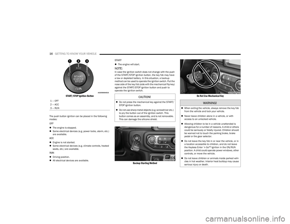
START/STOP Ignition Button
The push button ignition can be placed in the following
modes:
OFF
The engine is stopped.
Some electrical devices (e.g. power locks, alarm, etc.)
are available.
ACC
Engine is not started.
Some electrical devices (e.g. climate controls, heated
seats, etc.) are available.
RUN
Driving position.
All electrical devices are available. START
The engine will start.
NOTE:In case the ignition switch does not change with the push
of the START/STOP ignition button, the key fob may have
a low or depleted battery. In this situation, a backup
method can be used to operate the ignition switch. Put the
nose side of the key fob (side with the mechanical flip key)
against the START/STOP ignition button and push to
operate the ignition switch.
Backup Starting Method Do Not Use Mechanical Key
1 — OFF
2 — ACC
3 — RUNCAUTION!
Do not press the mechanical key against the START/
STOP ignition button.
Do not use sharp metal objects (e.g. screwdriver etc.)
to pry the button out of the ignition switch. This
button comes as an assembly, and is not removable.
This can damage the silicone shield.WARNING!
When exiting the vehicle, always remove the key fob
from the vehicle and lock your vehicle.
Never leave children alone in a vehicle, or with
access to an unlocked vehicle.
Allowing children to be in a vehicle unattended is
dangerous for a number of reasons. A child or others
could be seriously or fatally injured. Children should
be warned not to touch the parking brake, brake
pedal or the gear selector.
Do not leave the key fob in or near the vehicle, or in
a location accessible to children, and do not leave
the Keyless Enter ‘n Go™ Ignition in the ON/RUN
position. A child could operate power windows, other
controls, or move the vehicle.
Do not leave children or animals inside parked vehi -
cles in hot weather. Interior heat buildup may cause
serious injury or death.
23_JL_OM_EN_USC_t.book Page 16
Page 19 of 396
GETTING TO KNOW YOUR VEHICLE17
NOTE:
For more information on normal starting, see Úpage 126.
When opening the driver's door with the ignition in the
ON/RUN position (engine not running), a chime will
sound to remind you to place the ignition in the OFF
position. In addition to the chime, the message will
display “Ignition Or Accessory On” in the cluster.
REMOTE START — IF EQUIPPED
(GASOLINE)
If applicable, refer to the “Hybrid Supplement” for
additional information.
This system uses the key fob to start the engine
conveniently from outside the vehicle while still
maintaining security. The system has a range
of 328 ft (100 m).
Remote Start is used to defrost windows in cold weather,
and to reach a comfortable climate in all ambient
conditions before the driver enters the vehicle.
NOTE:
The vehicle must be equipped with an automatic trans -
mission to be equipped with Remote Start.
Obstructions between the vehicle and key fob may
reduce this range
Úpage 381.
HOW TO USE REMOTE START
Push and release the Remote Start button on the key fob
twice within five seconds. The vehicle doors and swing
gate will lock, the turn signals will flash twice, and the horn
will chirp twice. Pushing the Remote Start button again will
shut the engine off.
NOTE:
With Remote Start, the engine will only run for
15 minutes.
Remote Start can only be used twice.
If an engine fault is present or fuel level is low, the
vehicle will start and then shut down in 10 seconds.
The park lamps will turn on and remain on during
Remote Start mode.
For security, power window operation is disabled when
the vehicle is in the Remote Start mode.
The ignition must be placed in the ON/RUN position
before the Remote Start sequence can be repeated for
a third cycle.
All of the following conditions must be met before the
engine will remote start:
Gear selector in PARK
Doors closed
Hood closed
Swing gate closed
Hazard switch off
Brake switch inactive (brake pedal not pressed)
Battery at an acceptable charge level
Panic button not pushed
System not disabled from previous Remote Start event
Vehicle Security system indicator flashing
Ignition in OFF position
Fuel level meets minimum requirement
All removable doors must not be removed
Malfunction Indicator Light (MIL) not illuminated
CAUTION!
An unlocked vehicle is an invitation for thieves. Always
remove key fob from the vehicle and lock all doors
when leaving the vehicle unattended.
WARNING!
Do not start or run an engine in a closed garage or
confined area. Exhaust gas contains carbon
monoxide (CO) which is odorless and colorless.
Carbon monoxide is poisonous and can cause
serious injury or death when inhaled.
Keep key fobs away from children. Operation of the
Remote Start system, windows, door locks or other
controls could cause serious injury or death.
2
23_JL_OM_EN_USC_t.book Page 17
Page 21 of 396
GETTING TO KNOW YOUR VEHICLE19
REMOTE START — IF EQUIPPED (DIESEL)
This system uses the key fob to start the engine
conveniently from outside the vehicle while still
maintaining security. The system has a range
of approximately 300 ft (91 m).
Remote Start is used to defrost windows in cold weather,
and to reach a comfortable climate in all ambient
conditions before the driver enters the vehicle.
NOTE:
The vehicle must be equipped with an automatic trans -
mission to be equipped with Remote Start.
Obstructions between the vehicle and the key fob may
reduce this range.
The Remote Start system will wait for the Wait To Start
Indicator Light
Úpage 116 to extinguish before
cranking the engine. This allows time for the engine
preheat cycle to heat the cylinder air, and is normal in
cold weather.
HOW TO USE REMOTE START
Push and release the Remote Start button on the key fob
twice within five seconds. The vehicle doors and swing
gate will lock, the turn signals will flash twice, and the horn
will chirp twice. Pushing the Remote Start button again will
shut the engine off.
NOTE:
With Remote Start, the engine will only run for
15 minutes.
Remote Start can only be used twice.
If an engine fault is present or fuel level is low, the
vehicle will start and then shut down in 10 seconds.
The park lamps will turn on and remain on during
Remote Start mode.
For security, power window operation is disabled when
the vehicle is in the Remote Start mode.
The ignition must be placed in the ON/RUN position
before the Remote Start sequence can be repeated for
a third cycle.
All of the following conditions must be met before the
engine will remote start:
Gear selector in PARK
Doors closed
Hood closed
Swing gate closed
Hazard switch off
Brake switch inactive (brake pedal not pressed)
Battery at an acceptable charge level
Panic button not pushed
Fuel meets minimum requirement
System not disabled from previous Remote Start event
Vehicle Security system not active
Malfunction Indicator Light (MIL) is not illuminated
Water In Fuel Indicator Light is not illuminated
Wait To Start Indicator Light is not illuminated
For additional Remote Start information, see
Úpage 18.
VEHICLE SECURITY SYSTEM — IF EQUIPPED
The Vehicle Security system monitors the vehicle doors for
unauthorized entry and the ignition switch for
unauthorized operation. When the alarm is activated, the
interior switches for door locks are disabled. The Vehicle
Security system provides both audible and visible signals.
If something triggers the alarm, the Vehicle Security
system will provide the following audible and visible
signals: the horn will pulse, the park lamps and/or turn
signals will flash, and the Vehicle Security Light in the
instrument cluster will flash.WARNING!
Do not start or run an engine in a closed garage or
confined area. Exhaust gas contains carbon
monoxide (CO) which is odorless and colorless.
Carbon monoxide is poisonous and can cause
serious injury or death when inhaled.
Keep key fobs away from children. Operation of the
Remote Start system, windows, door locks or other
controls could cause serious injury or death.
WARNING!
Do not start or run an engine in a closed garage or
confined area. Exhaust gas contains carbon
monoxide (CO) which is odorless and colorless.
Carbon monoxide is poisonous and can cause
serious injury or death when inhaled.
Keep key fobs away from children. Operation of the
Remote Start system, windows, door locks or other
controls could cause serious injury or death.2
23_JL_OM_EN_USC_t.book Page 19
Page 23 of 396
GETTING TO KNOW YOUR VEHICLE21
(Continued)
NOTE:The mechanical key can be used to lock or unlock the
doors, swing gate (if equipped with a lock), glove
compartment, and console storage.POWER DOOR LOCKS — IF EQUIPPED
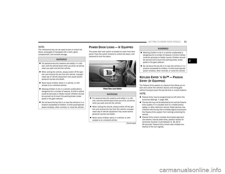
The power door lock switch is located on each front door
panel. Push the switch forward to unlock the doors, and
rearward to lock the doors.
Power Door Lock Switch
KEYLESS ENTER ‘N GO™ — PASSIVE
E
NTRY (IF EQUIPPED)
The Passive Entry system is a feature that allows you to
lock and unlock the vehicle’s door(s) and swing gate
without having to push the key fob lock or unlock buttons.
NOTE:
Passive Entry may be programmed on/off within the
Uconnect Settings Úpage 184.
The key fob may not be detected by the vehicle Passive
Entry system if it is located next to a mobile phone,
laptop, or other electronic device; these devices may
interfere with the key fob’s wireless signal and prevent
the Passive Entry system from locking/unlocking the
vehicle.
Passive Entry Unlock initiates illuminated approach
(low beams, license plate lamp, position lamps) for
whichever duration is set between 0, 30, 60 or
90 seconds. Passive Entry Unlock also initiates two
flashes of the turn signals.
WARNING!
For personal security reasons and safety in a colli -
sion, lock the vehicle doors when you drive, as well as
when you park and exit the vehicle.
When exiting the vehicle, always switch off the igni -
tion and remove the key from the vehicle. Unsuper -
vised use of vehicle equipment may cause severe
personal injuries and death.
Never leave children alone in a vehicle, or with
access to an unlocked vehicle.
Allowing children to be in a vehicle unattended is
dangerous for a number of reasons. A child or others
could be seriously or fatally injured. Children should
be warned not to touch the parking brake, brake
pedal or the gear selector.
Do not leave the key fob in or near the vehicle or in a
location accessible to children. A child could operate
power windows, other controls, or move the vehicle.
WARNING!
2
23_JL_OM_EN_USC_t.book Page 21
Page 26 of 396
24GETTING TO KNOW YOUR VEHICLE
NOTE:
When the Child-Protection Door Lock system is
engaged, the door can be opened only by using the
outside door handle even though the inside door lock
is in the unlocked position.
After disengaging the Child-Protection Door Lock
system, always test the door from the inside to make
certain it is in the unlocked position.
After engaging the Child-Protection Door Lock system,
always test the door from the inside to make certain it
is in the locked position.
For emergency exit with the system engaged, move the
lock lever rearward (located on the door trim panel),
lower the window and open the door with the outside
door handle.
NOTE:Always use this device when carrying children. After
engaging the child lock on both rear doors, check for
effective engagement by trying to open a door with the
internal handle. Once the Child-Protection Door Lock
system is engaged, it is impossible to open the doors from
inside the vehicle. Before getting out of the car, be sure to
check that there is no one left inside.
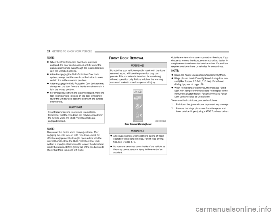
FRONT DOOR REMOVAL
Door Removal Warning Label
Outside rearview mirrors are mounted on the doors. If you
choose to remove the doors, see an authorized dealer for
a replacement cowl-mounted outside mirror. Federal law
requires outside mirrors on vehicles for on-road use.
NOTE:
Doors are heavy; use caution when removing them.
Hinge pin can break if overtightened during door rein -
stall (Max Torque: 7.5 ft· lb / 10 N·m). For off-road
driving tips, see
Úpage 178.
When front doors are removed, the message “Blind
Spot Alert Temporarily Unavailable” will display in the
instrument cluster display. Power Mirrors and Power
Door Locks will also be unavailable.
To remove the front doors, proceed as follows:
1. Roll down the glass window to prevent any damage.
2. Remove the hinge pin screws from the upper and lower outside hinges (using a #T50 Torx head driver).
WARNING!
Avoid trapping anyone in a vehicle in a collision.
Remember that the rear doors can only be opened from
the outside when the Child-Protection locks are
engaged (locked).
WARNING!
Do not drive your vehicle on public roads with the doors
removed as you will lose the protection they can
provide. This procedure is furnished for use during
off-road operation only. Failure to follow this warning
can result in death or serious personal injury.
WARNING!
All occupants must wear seat belts during off-road
operation with doors removed. For off-road driving
tips, see
Úpage 178.
Do not store detached doors inside of the vehicle, as
they may cause personal injury in the event of an
accident.
23_JL_OM_EN_USC_t.book Page 24
Page 30 of 396
28GETTING TO KNOW YOUR VEHICLE
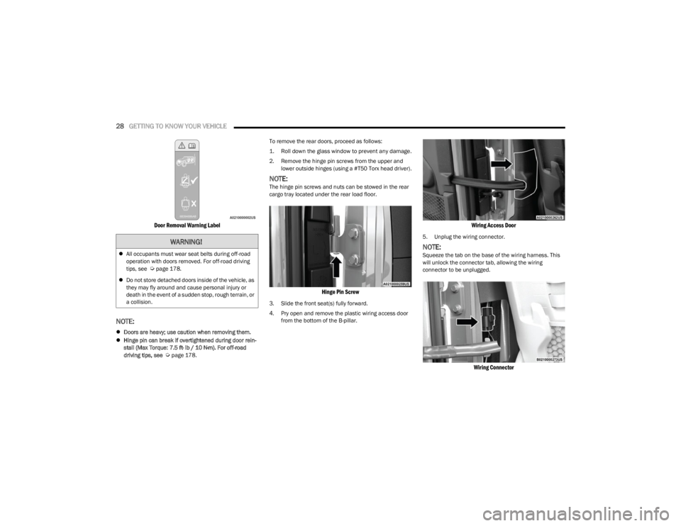
Door Removal Warning Label
NOTE:
Doors are heavy; use caution when removing them.
Hinge pin can break if overtightened during door rein -
stall (Max Torque: 7.5 ft· lb / 10 N·m). For off-road
driving tips, see
Úpage 178. To remove the rear doors, proceed as follows:
1. Roll down the glass window to prevent any damage.
2. Remove the hinge pin screws from the upper and
lower outside hinges (using a #T50 Torx head driver).
NOTE:The hinge pin screws and nuts can be stowed in the rear
cargo tray located under the rear load floor.
Hinge Pin Screw
3. Slide the front seat(s) fully forward.
4. Pry open and remove the plastic wiring access door from the bottom of the B-pillar.
Wiring Access Door
5. Unplug the wiring connector.
NOTE:Squeeze the tab on the base of the wiring harness. This
will unlock the connector tab, allowing the wiring
connector to be unplugged.
Wiring Connector
WARNING!
All occupants must wear seat belts during off-road
operation with doors removed. For off-road driving
tips, see
Úpage 178.
Do not store detached doors inside of the vehicle, as
they may fly around and cause personal injury or
death in the event of a sudden stop, rough terrain, or
a collision.
23_JL_OM_EN_USC_t.book Page 28
Page 33 of 396
GETTING TO KNOW YOUR VEHICLE31
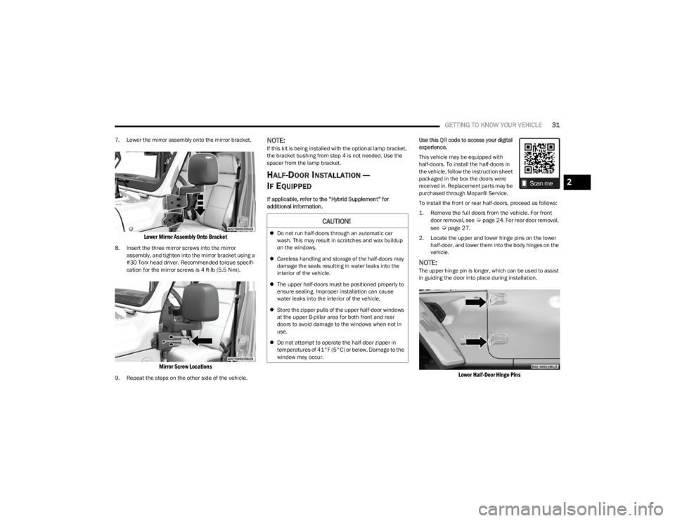
7. Lower the mirror assembly onto the mirror bracket.
Lower Mirror Assembly Onto Bracket
8. Insert the three mirror screws into the mirror
assembly, and tighten into the mirror bracket using a
#30 Torx head driver. Recommended torque specifi -
cation for the mirror screws is 4 ft-lb (5.5 N·m).
Mirror Screw Locations
9. Repeat the steps on the other side of the vehicle.
NOTE:If this kit is being installed with the optional lamp bracket,
the bracket bushing from step 4 is not needed. Use the
spacer from the lamp bracket.
HALF-DOOR INSTALLATION —
I
F EQUIPPED
If applicable, refer to the “Hybrid Supplement” for
additional information. Use this QR code to access your digital
experience.
This vehicle may be equipped with
half-doors. To install the half-doors in
the vehicle, follow the instruction sheet
packaged in the box the doors were
received in. Replacement parts may be
purchased through Mopar® Service.
To install the front or rear half-doors, proceed as follows:
1. Remove the full doors from the vehicle. For front
door removal, see
Ú
page 24
. For rear door removal,
see Ú
page 27.
2. Locate the upper and lower hinge pins on the lower half-door, and lower them into the body hinges on the
vehicle.
NOTE:The upper hinge pin is longer, which can be used to assist
in guiding the door into place during installation.
Lower Half-Door Hinge Pins
CAUTION!
Do not run half-doors through an automatic car
wash. This may result in scratches and wax buildup
on the windows.
Careless handling and storage of the half-doors may
damage the seals resulting in water leaks into the
interior of the vehicle.
The upper half-doors must be positioned properly to
ensure sealing. Improper installation can cause
water leaks into the interior of the vehicle.
Store the zipper pulls of the upper half-door windows
at the upper B-pillar area for both front and rear
doors to avoid damage to the windows when not in
use.
Do not attempt to operate the half-door zipper in
temperatures of 41°F (5°C) or below. Damage to the
window may occur.
2
23_JL_OM_EN_USC_t.book Page 31
Page 34 of 396
32GETTING TO KNOW YOUR VEHICLE
3. Insert the upper and lower hinge pin screws into the
body hinges. Tighten the screws using a #T50 Torx
head driver to 3.8 ft· lb / 5.2 N·m.
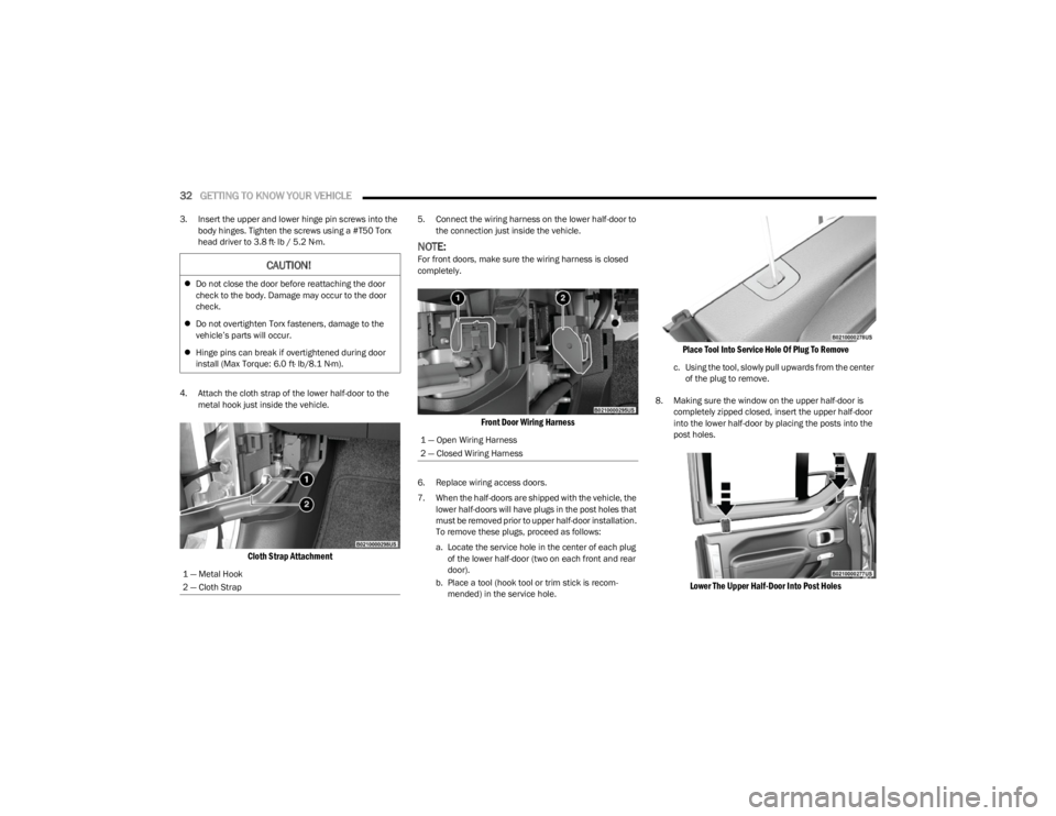
4. Attach the cloth strap of the lower half-door to the metal hook just inside the vehicle.
Cloth Strap Attachment
5. Connect the wiring harness on the lower half-door to the connection just inside the vehicle.
NOTE:For front doors, make sure the wiring harness is closed
completely.
Front Door Wiring Harness
6. Replace wiring access doors.
7. When the half-doors are shipped with the vehicle, the lower half-doors will have plugs in the post holes that
must be removed prior to upper half-door installation.
To remove these plugs, proceed as follows:
a. Locate the service hole in the center of each plug of the lower half-door (two on each front and rear
door).
b. Place a tool (hook tool or trim stick is recom -
mended) in the service hole.
Place Tool Into Service Hole Of Plug To Remove
c. Using the tool, slowly pull upwards from the center of the plug to remove.
8. Making sure the window on the upper half-door is completely zipped closed, insert the upper half-door
into the lower half-door by placing the posts into the
post holes.
Lower The Upper Half-Door Into Post Holes
CAUTION!
Do not close the door before reattaching the door
check to the body. Damage may occur to the door
check.
Do not overtighten Torx fasteners, damage to the
vehicle’s parts will occur.
Hinge pins can break if overtightened during door
install (Max Torque: 6.0 ft· lb/8.1 N·m).
1 — Metal Hook
2 — Cloth Strap
1 — Open Wiring Harness
2 — Closed Wiring Harness
23_JL_OM_EN_USC_t.book Page 32