fuel pressure JEEP WRANGLER 2DOORS 2018 Owner handbook (in English)
[x] Cancel search | Manufacturer: JEEP, Model Year: 2018, Model line: WRANGLER 2DOORS, Model: JEEP WRANGLER 2DOORS 2018Pages: 348, PDF Size: 6.5 MB
Page 74 of 348
CAUTION!
age to the vehicle control system. It also
could affect fuel economy and driveability.
If the MIL is flashing, severe catalytic
converter damage and power loss will soon
occur. Immediate service is required.
— AdBlue (UREA) Injection System
Failure Warning Light — If Equipped
This warning light will illuminate along with a
dedicated message on the display (If
Equipped) if an unknown fluid not conform-
ing with acceptable characteristics is in-
serted, or if an average consumption of Ad-
Blue (UREA) over 50% is detected. Contact
an authorized dealer as soon as possible.
If the problem is not solved, a specific mes-
sage will appear on the Instrument Cluster
Display whenever a certain threshold is
reached until it will no longer be possible to
start the engine.When about 125 mi (200 km) are remaining
before the AdBlue (UREA) tank is empty, a
continuous dedicated message will appear on
the instrument panel, accompanied by a
buzzer sound (If Equipped).
SERV4WD— Service 4WD Warning Light — If
Equipped
This warning light will illuminate to signal a
fault with the 4WD system. If the light stays
on or comes on during driving, it means that
the 4WD system is not functioning properly
and that service is required. We recommend
you drive to the nearest service center and
have the vehicle serviced immediately.
— Service Stop/Start System Warning
Light — If Equipped
This warning light will illuminate when the
Stop/Start system is not functioning properly
and service is required. Contact an autho-
rized dealer for service.
— Speed Control Fault Warning Light
This warning light will illuminate to indicate
the Speed Control System is not functioning
properly and service is required. Contact an
authorized dealer.
— Sway Bar Fault Warning Light
This light will illuminate when there is a fault
in the sway bar disconnect system.
— Tire Pressure Monitoring System
(TPMS) Warning Light
The warning light switches on and a message
is displayed to indicate that the tire pressure
is lower than the recommended value and/or
that slow pressure loss is occurring. In these
cases, optimal tire duration and fuel con-
sumption may not be guaranteed.
Should one or more tires be in the condition
mentioned above, the display will show the
indications corresponding to each tire.
CAUTION!
Do not continue driving with one or more
flat tires as handling may be compro-GETTING TO KNOW YOUR INSTRUMENT PANEL
72
Page 75 of 348
CAUTION!
mised. Stop the vehicle, avoiding sharp
braking and steering. If a tire puncture
occurs, repair immediately using the dedi-
cated tire repair kit and contact an autho-
rized dealer as soon as possible.
Each tire, including the spare (if provided),
should be checked monthly when cold and
inflated to the inflation pressure recom-
mended by the vehicle manufacturer on the
vehicle placard or tire inflation pressure la-
bel. (If your vehicle has tires of a different
size than the size indicated on the vehicle
placard or tire inflation pressure label, you
should determine the proper tire inflation
pressure for those tires.)
As an added safety feature, your vehicle has
been equipped with a Tire Pressure Monitor-
ing System (TPMS) that illuminates a low tire
pressure telltale when one or more of your
tires is significantly under-inflated. Accord-
ingly, when the low tire pressure telltale illu-
minates, you should stop and check your tires
as soon as possible, and inflate them to the
proper pressure. Driving on a significantlyunder-inflated tire causes the tire to overheat
and can lead to tire failure. Under-inflation
also reduces fuel efficiency and tire tread
life, and may affect the vehicle’s handling
and stopping ability.
Please note that the TPMS is not a substitute
for proper tire maintenance, and it is the
driver’s responsibility to maintain correct tire
pressure, even if under-inflation has not
reached the level to trigger illumination of the
TPMS low tire pressure telltale.
Your vehicle has also been equipped with a
TPMS malfunction indicator to indicate when
the system is not operating properly. The
TPMS malfunction indicator is combined
with the low tire pressure telltale. When the
system detects a malfunction, the telltale will
flash for approximately one minute and then
remain continuously illuminated. This se-
quence will continue upon subsequent ve-
hicle start-ups as long as the malfunction
exists. When the malfunction indicator is
illuminated, the system may not be able to
detect or signal low tire pressure as intended.
TPMS malfunctions may occur for a variety of
reasons, including the installation of replace-ment or alternate tires or wheels on the ve-
hicle that prevent the TPMS from functioning
properly. Always check the TPMS malfunc-
tion telltale after replacing one or more tires
or wheels on your vehicle to ensure that the
replacement or alternate tires and wheels
allow the TPMS to continue to function
properly.
CAUTION!
The TPMS has been optimized for the
original equipment tires and wheels.
TPMS pressures and warning have been
established for the tire size equipped on
your vehicle. Undesirable system opera-
tion or sensor damage may result when
using replacement equipment that is not
of the same size, type, and/or style. After-
market wheels can cause sensor damage.
Using aftermarket tire sealants may cause
the Tire Pressure Monitoring System
(TPMS) sensor to become inoperable. Af-
ter using an aftermarket tire sealant it is
recommended that you take your vehicle to
your authorized dealer to have your sensor
function checked.
73
Page 97 of 348
The system will automatically update and the
TPMS Warning Light will turn off once the
system receives the updated tire pressures.
The vehicle may need to be driven for up to
10 minutes above 15 mph (24 km/h) in order
for the TPMS to receive this information.
For example, your vehicle may have a recom-
mended cold (parked for more than three
hours) placard pressure of 33 psi (227 kPa).
If the ambient temperature is 68°F (20°C)
and the measured tire pressure is 28 psi
(193 kPa), a temperature drop to 20°F (-7°C)
will decrease the tire pressure to approxi-
mately 24 psi (165 kPa). This tire pressure is
low enough to turn on the TPMS Warning
Light. Driving the vehicle may cause the tire
pressure to rise to approximately 28 psi
(193 kPa), but the TPMS Warning Light will
still be on. In this situation, the TPMS Warn-
ing Light will turn off only after the tires are
inflated to the vehicle’s recommended cold
placard pressure value.NOTE:
When filling warm tires, the tire pressure may
need to be increased up to an additional 4 psi
(28 kPa) above the recommended cold plac-
ard pressure in order to turn the TPMS Warn-
ing Light off.
CAUTION!
• The TPMS has been optimized for the
original equipment tires and wheels.
TPMS pressures and warning have been
established for the tire size equipped on
your vehicle. Undesirable system opera-
tion or sensor damage may result when
using replacement equipment that is not
of the same size, type, and/or style. The
TPM sensor is not designed for use on
aftermarket wheels, and may contribute
to a poor overall system performance.
Customers are encouraged to use OEM
wheels to assure TPMS feature opera-
tion.
• Using aftermarket tire sealants may
cause the Tire Pressure Monitoring Sys-
tem (TPMS) sensor to become inoper-
able. After using an aftermarket tire
CAUTION!
sealant it is recommended that you take
your vehicle to an authorized dealer to
have your sensor function checked.
• After inspecting or adjusting the tire
pressure always reinstall the valve stem
cap. This will prevent moisture and dirt
from entering the valve stem, which
could damage the TPMS sensor.
NOTE:
• The TPMS is not intended to replace nor-
mal tire care and maintenance, or to pro-
vide warning of a tire failure or condition.
• The TPMS should not be used as a tire
pressure gauge while adjusting your tire
pressure.
• Driving on a significantly underinflated tire
causes the tire to overheat and can lead to
tire failure. Underinflation also reduces
fuel efficiency and tire tread life, and may
affect the vehicle’s handling and stopping
ability.
• The TPMS is not a substitute for proper tire
maintenance, and it is the driver’s respon-
sibility to maintain correct tire pressure
95
Page 141 of 348
WARNING!
• NEVER place any objects under the floor
mat (e.g., towels, keys, etc.). These ob-
jects could change the position of the
floor mat and may cause interference
with the accelerator, brake, or clutch
pedals.
• If the vehicle carpet has been removed
and re-installed, always properly attach
carpet to the floor and check the floor
mat fasteners are secure to the vehicle
carpet. Fully depress each pedal to
check for interference with the accelera-
tor, brake, or clutch pedals then re-
install the floor mats.
• It is recommended to only use mild soap
and water to clean your floor mats. After
cleaning, always check your floor mat
WARNING!
has been properly installed and is se-
cured to your vehicle using the floor mat
fasteners by lightly pulling mat.
Periodic Safety Checks You Should Make
Outside The Vehicle
Tires
Examine tires for excessive tread wear and
uneven wear patterns. Check for stones,
nails, glass, or other objects lodged in the
tread or sidewall. Inspect the tread for cuts
and cracks. Inspect sidewalls for cuts,
cracks, and bulges. Check the wheel nuts for
tightness. Check the tires (including spare)
for proper cold inflation pressure.
Lights
Have someone observe the operation of brake
lights and exterior lights while you work the
controls. Check turn signal and high beam
indicator lights on the instrument panel.
Door Latches
Check for proper closing, latching, and lock-
ing.
Fluid Leaks
Check area under the vehicle after overnight
parking for fuel, coolant, oil, or other fluid
leaks. Also, if gasoline fumes are detected or
if fuel, or brake fluid leaks are suspected. The
cause should be located and corrected imme-
diately.
139
Page 147 of 348
ALWAYS DO A VISUAL CHECKthat your vehicle
is in PARK by looking for the "P" in the
instrument cluster display and on the shifter.
As an added precaution, always apply the
parking brake when exiting the vehicle.
Normal Starting — Diesel Engine
1. The gear selector must be in the NEU-
TRAL or PARK position before you can
start the engine.
2. Place the ignition in the ON position.
3. Watch for the “Wait To Start Light” in the
instrument cluster. Refer to “Instrument
Cluster” in “Getting To Know Your Instru-
ment Panel” for further review. It will glow
for two to ten seconds or more, depending
on engine temperature. When the “Wait
To Start Light” goes out, the engine is
ready to start.
4. Tip Start Feature
Do notpress the accelerator. Cycle the
ignition to the START position and then
release it. The starter motor will continue
to run, and it will automatically disengage
when the engine is running. If the engine
fails to start, the starter will disengageautomatically in 25 seconds. If this oc-
curs, cycle the ignition to the LOCK posi-
tion, wait 25 to 30 seconds, then repeat
the “Normal Starting” procedure.
NOTE:
The starter motor may run up to 30 sec-
onds in very cold conditions until the
engine is started. The starter can be dis-
engaged by cycling the ignition to the
OFF position, if required.
5. After the engine starts, allow it to idle for
approximately 30 seconds before driving.
This allows oil to circulate and lubricate
the turbocharger.
Diesel Engine Warm-Up
Avoid full throttle operation when the engine
is cold. When starting a cold engine, bring the
engine up to operating speed slowly to allow
the oil pressure to stabilize as the engine
warms up.NOTE:
High-speed, no-load running of a cold engine
can result in excessive white smoke and poor
engine performance. No-load engine speeds
should be kept under 1,200 rpm during the
warm-up period, especially in cold, ambient
temperature conditions.
If temperatures are below 32°F (0°C), oper-
ate the engine at moderate speeds for five
minutes before full loads are applied.
Diesel Engine Idling — In Cold Weather
Avoid prolonged idling in ambient tempera-
tures below 0°F (-18°C). Long periods of
idling may be harmful to your engine because
combustion chamber temperatures can drop
so low that the fuel may not burn completely.
Incomplete combustion allows carbon and
varnish to form on piston rings and injector
nozzles. Also, the unburned fuel can enter
the crankcase, diluting the oil and causing
rapid wear to the engine.
145
Page 169 of 348
WARNING!
• Do not apply any object/cap to the end of
the filler which is not provided for the
car. The use of non-compliant objects/
plugs could cause a pressure increase
inside the tank, resulting in dangerous
situations.
• A fire may result if fuel is pumped into a
portable container that is inside of a
vehicle. You could be burned. Always
place fuel containers on the ground
while filling.
CAUTION!
• Damage to the fuel system or emission
control system could result from using
an improper fuel filler cap. A poorly
fitting cap could let impurities into the
fuel system. Also, a poorly fitting after-
market cap can cause the “Malfunction
Indicator Light (MIL)” to illuminate, due
to fuel vapors escaping from the system.
• To avoid fuel spillage and overfilling, do
not “top off” the fuel tank after filling.NOTE:
• When the fuel nozzle “clicks” or shuts off,
the fuel tank is full.
• Tighten the fuel filler cap about 1/4 turn
until you hear one click. This is an indica-
tion that the cap is properly tightened.
• If the fuel filler cap is not tightened prop-
erly, the MIL will come on. Be sure the cap
is tightened every time the vehicle is
refueled.
Loose Fuel Filler Cap Message
After fuel has been added, the vehicle diag-
nostic system can determine if the fuel filler
cap is possibly loose, improperly installed, or
damaged. If the system detects a malfunc-
tion, the “gASCAP” message will display in
the odometer display. Tighten the gas cap
until a "clicking" sound is heard. This is an
indication that the gas cap is properly tight-
ened. Push the odometer reset button to turn
the message off. If the problem persists, the
message will appear the next time the vehicle
is started. This might indicate a damagedcap. If the problem is detected twice in a row,
the system will turn on the MIL. Resolving the
problem will turn the MIL off.
REFUELING THE VEHICLE —
DIESEL
The fuel filler cap is located on the driver's
side of the vehicle. If the fuel filler cap is lost
or damaged, be sure the replacement cap is
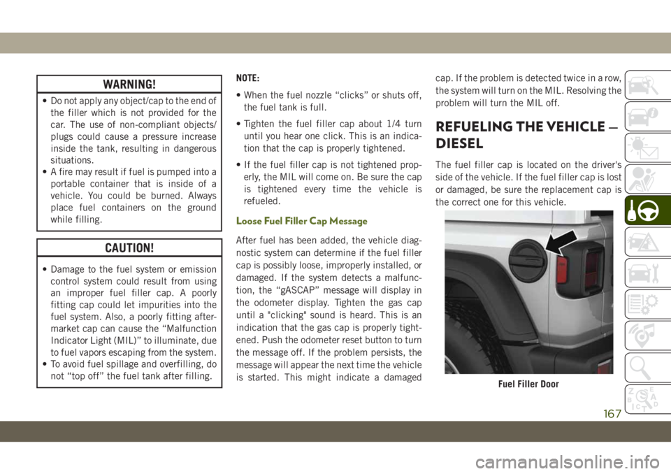
the correct one for this vehicle.
Fuel Filler Door
167
Page 170 of 348
WARNING!
• Never have any smoking materials lit in
or near the vehicle when the fuel door is
open or the tank is being filled.
• Never add fuel when the engine is run-
ning. This is in violation of most coun-
tries regulations and may cause the
“Malfunction Indicator Light” to turn
on.
WARNING!
• Do not apply any object/cap to the end of
the filler which is not provided for the
car. The use of non-compliant objects/
plugs could cause a pressure increase
inside the tank, resulting in dangerous
situations.
• A fire may result if fuel is pumped into a
portable container that is inside of a
vehicle. You could be burned. Always
place fuel containers on the ground
while filling.
CAUTION!
• Damage to the fuel system or emission
control system could result from using
an improper fuel filler cap. A poorly
fitting cap could let impurities into the
fuel system. Also, a poorly fitting after-
market cap can cause the “Malfunction
Indicator Light (MIL)” to illuminate, due
to fuel vapors escaping from the system.
• To avoid fuel spillage and overfilling, do
not “top off” the fuel tank after filling.NOTE:
• When the fuel nozzle “clicks” or shuts off,
the fuel tank is full.
• Tighten the fuel filler cap about 1/4 turn
until you hear one click. This is an indica-
tion that the cap is properly tightened.
• If the fuel filler cap is not tightened prop-
erly, the MIL will come on. Be sure the cap
is tightened every time the vehicle is
refueled.
Adblue (UREA) — If Equipped
The vehicle is equipped with an UREA injec-
tion system and Selective Catalytic Reduc-
tion to meet emission standards. These two
systems ensure compliance with the diesel
emissions requirements; at the same, they
ensure fuel-efficiency, handling, torque and
power. For messages and system warnings,
refer to the "Warning Lights And Messages" in
the "Getting To Know Your Instrument Panel"
section. AdBlue (UREA) is a very stable prod-
uct with a long shelf life. Stored at tempera-
tures LOWER than 90 °F (32 °C), it has a
shelf life of at least one year. For more infor-
mation on the AdBlue liquid type, see the
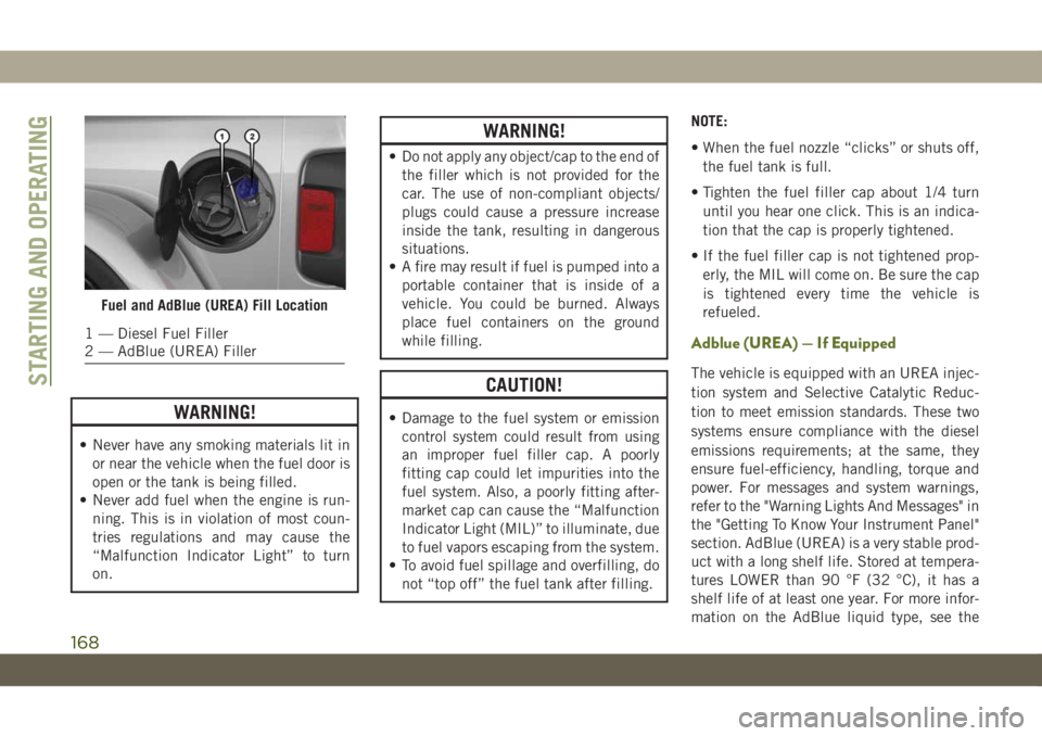
Fuel and AdBlue (UREA) Fill Location
1 — Diesel Fuel Filler
2 — AdBlue (UREA) Filler
STARTING AND OPERATING
168
Page 232 of 348
WARNING!
Overloading of your tires is dangerous.
Overloading can cause tire failure, affect
vehicle handling, and increase your stop-
ping distance. Use tires of the recom-
mended load capacity for your vehicle.
Never overload them.
Tires — General Information
Tire Pressure
Proper tire inflation pressure is essential to
the safe and satisfactory operation of your
vehicle. Four primary areas are affected by
improper tire pressure:
• Safety and Vehicle Stability
• Economy
• Tread Wear
• Ride ComfortSafety
WARNING!
• Improperly inflated tires are dangerous
and can cause collisions.
• Underinflation increases tire flexing and
can result in overheating and tire failure.
• Overinflation reduces a tire's ability to
cushion shock. Objects on the road and
chuckholes can cause damage that re-
sult in tire failure.
• Overinflated or underinflated tires can
affect vehicle handling and can fail sud-
denly, resulting in loss of vehicle con-
trol.
• Unequal tire pressures can cause steer-
ing problems. You could lose control of
your vehicle.
• Unequal tire pressures from one side of
the vehicle to the other can cause the
vehicle to drift to the right or left.
• Always drive with each tire inflated to
the recommended cold tire inflation
pressure.Both under-inflation and over-inflation affect
the stability of the vehicle and can produce a
feeling of sluggish response or over respon-
siveness in the steering.
NOTE:
• Unequal tire pressures from side to side
may cause erratic and unpredictable steer-
ing response.
• Unequal tire pressure from side to side may
cause the vehicle to drift left or right.
Fuel Economy
Underinflated tires will increase tire rolling
resistance resulting in higher fuel consump-
tion.
Tread Wear
Improper cold tire inflation pressures can
cause abnormal wear patterns and reduced
tread life, resulting in the need for earlier tire
replacement.
Ride Comfort And Vehicle Stability
Proper tire inflation contributes to a comfort-
able ride. Over-inflation produces a jarring
and uncomfortable ride.
SERVICING AND MAINTENANCE
230
Page 337 of 348
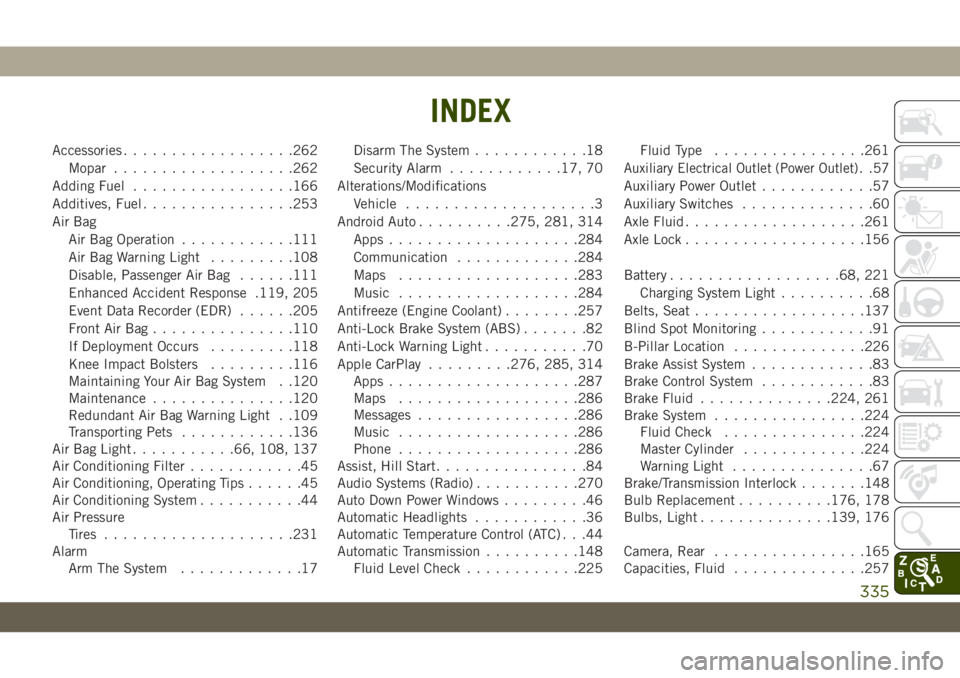
Accessories..................262
Mopar...................262
Adding Fuel.................166
Additives, Fuel................253
Air Bag
Air Bag Operation............111
Air Bag Warning Light.........108
Disable, Passenger Air Bag......111
Enhanced Accident Response .119, 205
Event Data Recorder (EDR)......205
Front Air Bag...............110
If Deployment Occurs.........118
Knee Impact Bolsters.........116
Maintaining Your Air Bag System . .120
Maintenance...............120
Redundant Air Bag Warning Light . .109
Transporting Pets............136
Air Bag Light...........66, 108, 137
Air Conditioning Filter............45
Air Conditioning, Operating Tips......45
Air Conditioning System...........44
Air Pressure
Tires....................231
Alarm
Arm The System.............17Disarm The System............18
Security Alarm............17, 70
Alterations/Modifications
Vehicle....................3
Android Auto..........275, 281, 314
Apps....................284
Communication.............284
Maps...................283
Music...................284
Antifreeze (Engine Coolant)........257
Anti-Lock Brake System (ABS).......82
Anti-Lock Warning Light...........70
Apple CarPlay.........276, 285, 314
Apps....................287
Maps...................286
Messages.................286
Music
...................286
Phone...................286
Assist, Hill Start................84
Audio Systems (Radio)...........270
Auto Down Power Windows.........46
Automatic Headlights............36
Automatic Temperature Control (ATC) . . .44
Automatic Transmission..........148
Fluid Level Check............225Fluid Type................261
Auxiliary Electrical Outlet (Power Outlet). .57
Auxiliary Power Outlet............57
Auxiliary Switches..............60
Axle Fluid...................261
Axle Lock...................156
Battery..................68, 221
Charging System Light..........68
Belts, Seat..................137
Blind Spot Monitoring............91
B-Pillar Location..............226
Brake Assist System.............83
Brake Control System............83
Brake Fluid..............224, 261
Brake System................224
Fluid Check...............224
Master Cylinder.............224
Warning Light...............67
Brake/Transmission Interlock.......148
Bulb Replacement..........176, 178
Bulbs, Light..............139, 176
Camera, Rear................165
Capacities, Fluid..............257
INDEX
335
Page 341 of 348
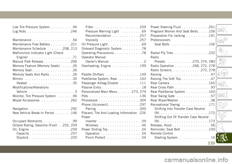
Low Tire Pressure System..........94
Lug Nuts...................246
Maintenance..................54
Maintenance Free Battery.........221
Maintenance Schedule.......208, 213
Malfunction Indicator Light (Check
Engine)...................71
Manual Park Release............200
Memory Feature (Memory Seats)......26
Memory Seat..................26
Memory Seats And Radio..........26
Mirrors.....................35
Heated...................35
Modifications/Alterations
Vehicle....................3
Monitor, Tire Pressure System.......94
Mopar Accessories.............262
Navigation..................292
New Vehicle Break-In Period.......146
Occupant Restraints.............99
Octane Rating, Gasoline (Fuel) . .252, 259
Oil, Engine..................259
Capacity.................257
Dipstick..................220Filter....................259
Pressure Warning Light.........69
Recommendation............257
Viscosity.................257
Oil Pressure Light...............69
Onboard Diagnostic System.........78
Operating Precautions............78
Operator Manual
Owner's Manual...............2
Overheating, Engine............199
Paddle Shifters...............149
ParkSense System, Rear..........163
Passenger Airbag Disable.........111
Passive Entry..................18
Personalized Main Menu......273, 279
Pets......................136
Phonebook..................304
Phone (Uconnect)..............297
Pairing
..................300
Placard, Tire And Loading Information .226
Power
Inverter...................59
Windows..................46
Power Sliding Top...............54
Operation..................54
Pinch Protect...............54Power Steering Fluid............261
Pregnant Women And Seat Belts.....106
Preparation For Jacking..........191
Pretensioners
Seat Belts................106
Radial Ply Tires...............232
Radio
Presets...........270, 274, 280
Radio Operation........268, 272, 278
Radio Screens.............272, 278
Raising.....................47
Raising The Soft Top.............47
Rear Camera.................165
Rear Cross Path................93
Rear ParkSense System..........163
Rear Swing Gate...............57
Rear Wiper/Washer..............38
Recreational Towing.............171
Shifting Into Transfer Case Neutral
(N) .....................172
Shifting Out Of Transfer Case Neutral
(N) .....................173
Release, Hood.................56
Reminder, Seat Belt............100
Remote Control
Starting System..............16
339