warning JEEP WRANGLER 2DOORS 2019 Owner handbook (in English)
[x] Cancel search | Manufacturer: JEEP, Model Year: 2019, Model line: WRANGLER 2DOORS, Model: JEEP WRANGLER 2DOORS 2019Pages: 348, PDF Size: 6.5 MB
Page 4 of 348
HOW TO USE THIS MANUAL
Essential Information
Consult the Table of Contents to determine
which section contains the information you
desire.
Since the specification of your vehicle de-
pends on the items of equipment ordered,
certain descriptions and illustrations may dif-
fer from your vehicle's equipment.
The detailed index at the back of this Owner's
Manual contains a complete listing of all
subjects.
Symbols
Some vehicle components have colored la-
bels whose symbols indicate precautions to
be observed when using this component.
Refer to “Warning Lights and Messages” in
“Getting To Know Your Instrument Panel” for
further information on the symbols used in
your vehicle.
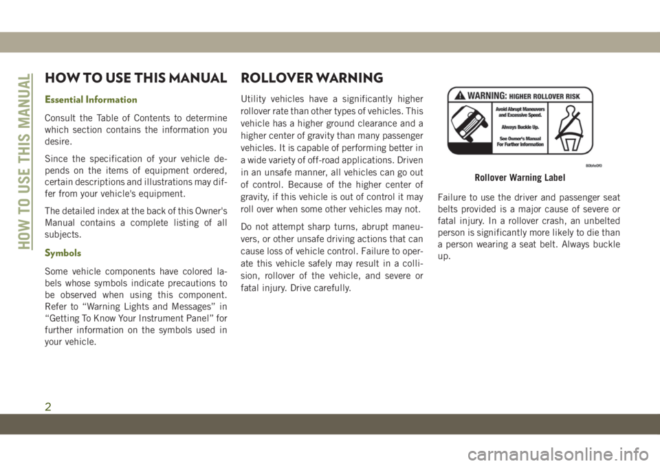
ROLLOVER WARNING
Utility vehicles have a significantly higher
rollover rate than other types of vehicles. This
vehicle has a higher ground clearance and a
higher center of gravity than many passenger
vehicles. It is capable of performing better in
a wide variety of off-road applications. Driven
in an unsafe manner, all vehicles can go out
of control. Because of the higher center of
gravity, if this vehicle is out of control it may
roll over when some other vehicles may not.
Do not attempt sharp turns, abrupt maneu-
vers, or other unsafe driving actions that can
cause loss of vehicle control. Failure to oper-
ate this vehicle safely may result in a colli-
sion, rollover of the vehicle, and severe or
fatal injury. Drive carefully.Failure to use the driver and passenger seat
belts provided is a major cause of severe or
fatal injury. In a rollover crash, an unbelted
person is significantly more likely to die than
a person wearing a seat belt. Always buckle
up.
Rollover Warning Label
HOW TO USE THIS MANUAL
2
Page 5 of 348
WARNINGS AND CAUTIONS
This User Guide containsWARNINGSagainst
operating procedures that could result in a
collision, bodily injury and/or death. It also
containsCAUTIONSagainst procedures that
could result in damage to your vehicle. If you
do not read this entire guide, you may miss
important information. Observe all Warnings
and Cautions.
VEHICLE MODIFICATIONS/
ALTERATIONS
WARNING!
Any modifications or alterations to this
vehicle could seriously affect its roadwor-
thiness and safety and may lead to a col-
lision resulting in serious injury or death.
HOW TO USE THIS MANUAL
3
Page 15 of 348
KEYS
Key Fob
WARNING!
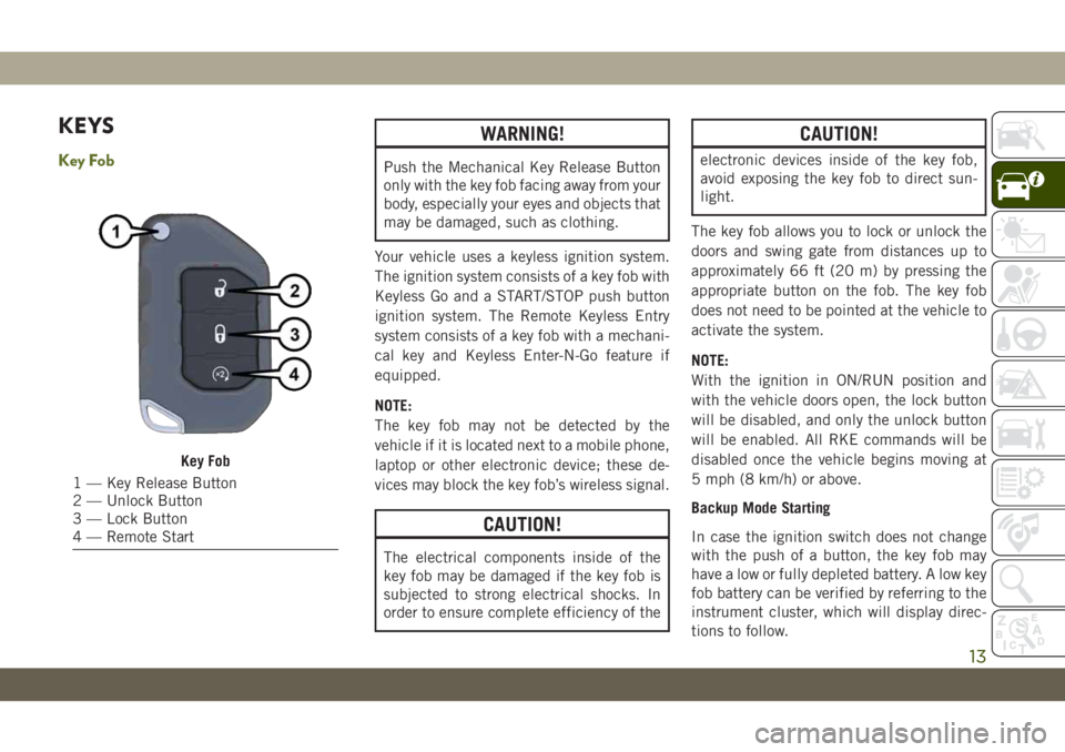
Push the Mechanical Key Release Button
only with the key fob facing away from your
body, especially your eyes and objects that
may be damaged, such as clothing.
Your vehicle uses a keyless ignition system.
The ignition system consists of a key fob with
Keyless Go and a START/STOP push button
ignition system. The Remote Keyless Entry
system consists of a key fob with a mechani-
cal key and Keyless Enter-N-Go feature if
equipped.
NOTE:
The key fob may not be detected by the
vehicle if it is located next to a mobile phone,
laptop or other electronic device; these de-
vices may block the key fob’s wireless signal.
CAUTION!
The electrical components inside of the
key fob may be damaged if the key fob is
subjected to strong electrical shocks. In
order to ensure complete efficiency of the
CAUTION!
electronic devices inside of the key fob,
avoid exposing the key fob to direct sun-
light.
The key fob allows you to lock or unlock the
doors and swing gate from distances up to
approximately 66 ft (20 m) by pressing the
appropriate button on the fob. The key fob
does not need to be pointed at the vehicle to
activate the system.
NOTE:
With the ignition in ON/RUN position and
with the vehicle doors open, the lock button
will be disabled, and only the unlock button
will be enabled. All RKE commands will be
disabled once the vehicle begins moving at
5 mph (8 km/h) or above.
Backup Mode Starting
In case the ignition switch does not change
with the push of a button, the key fob may
have a low or fully depleted battery. A low key
fob battery can be verified by referring to the
instrument cluster, which will display direc-
tions to follow.
Key Fob
1 — Key Release Button
2 — Unlock Button
3 — Lock Button
4 — Remote Start
13
Page 16 of 348
NOTE:
A low key fob battery condition may be indi-
cated by a message in the instrument cluster
display, or by the LED light on the key fob. If
the LED key fob light no longer illuminates
from key fob button pushes, then the key fob
battery requires replacement.
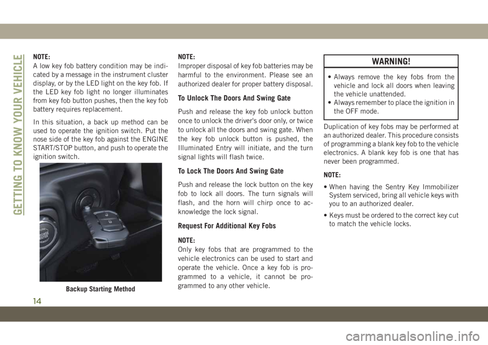
In this situation, a back up method can be
used to operate the ignition switch. Put the
nose side of the key fob against the ENGINE
START/STOP button, and push to operate the
ignition switch.NOTE:
Improper disposal of key fob batteries may be
harmful to the environment. Please see an
authorized dealer for proper battery disposal.
To Unlock The Doors And Swing Gate
Push and release the key fob unlock button
once to unlock the driver's door only, or twice
to unlock all the doors and swing gate. When
the key fob unlock button is pushed, the
Illuminated Entry will initiate, and the turn
signal lights will flash twice.
To Lock The Doors And Swing Gate
Push and release the lock button on the key
fob to lock all doors. The turn signals will
flash, and the horn will chirp once to ac-
knowledge the lock signal.
Request For Additional Key Fobs
NOTE:
Only key fobs that are programmed to the
vehicle electronics can be used to start and
operate the vehicle. Once a key fob is pro-
grammed to a vehicle, it cannot be pro-
grammed to any other vehicle.
WARNING!
• Always remove the key fobs from the
vehicle and lock all doors when leaving
the vehicle unattended.
• Always remember to place the ignition in
the OFF mode.
Duplication of key fobs may be performed at
an authorized dealer. This procedure consists
of programming a blank key fob to the vehicle
electronics. A blank key fob is one that has
never been programmed.
NOTE:
• When having the Sentry Key Immobilizer
System serviced, bring all vehicle keys with
you to an authorized dealer.
• Keys must be ordered to the correct key cut
to match the vehicle locks.
Backup Starting Method
GETTING TO KNOW YOUR VEHICLE
14
Page 17 of 348
IGNITION SWITCH
Keyless Enter-N-Go — Ignition
This feature allows the driver to operate the
ignition switch with the push of a button as
long as the key fob is in the passenger com-
partment.
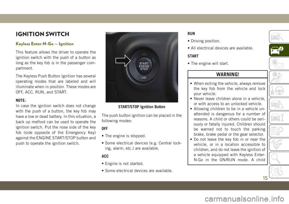
The Keyless Push Button Ignition has several
operating modes that are labeled and will
illuminate when in position. These modes are
OFF, ACC, RUN, and START.
NOTE:
In case the ignition switch does not change
with the push of a button, the key fob may
have a low or dead battery. In this situation, a
back up method can be used to operate the
ignition switch. Put the nose side of the key
fob (side opposite of the Emergency Key)
against the ENGINE START/STOP button and
push to operate the ignition switch.The push button ignition can be placed in the
following modes:
OFF
• The engine is stopped.
• Some electrical devices (e.g. Central lock-
ing, alarm, etc.) are available.
ACC
• Engine is not started.
• Some electrical devices are available.RUN
• Driving position.
• All electrical devices are available.
START
• The engine will start.
WARNING!
• When exiting the vehicle, always remove
the key fob from the vehicle and lock
your vehicle.
• Never leave children alone in a vehicle,
or with access to an unlocked vehicle.
• Allowing children to be in a vehicle un-
attended is dangerous for a number of
reasons. A child or others could be seri-
ously or fatally injured. Children should
be warned not to touch the parking
brake, brake pedal or the gear selector.
• Do not leave the key fob in or near the
vehicle, or in a location accessible to
children, and do not leave the ignition of
a vehicle equipped with Keyless Enter-
N-Go in the ON/RUN mode. A child
START/STOP Ignition Button
15
Page 18 of 348
WARNING!
could operate power windows, other con-
trols, or move the vehicle.
• Do not leave children or animals inside
parked vehicles in hot weather. Interior
heat build-up may cause serious injury
or death.
CAUTION!
An unlocked vehicle is an invitation for
thieves. Always remove key fob from the
vehicle and lock all doors when leaving the
vehicle unattended.
NOTE:
Refer to "Starting The Engine," in "Starting
And Operating" in the Owner’s Manual for
further information.
REMOTE STARTING
SYSTEM — IF EQUIPPED
This system uses the key fob to
start the engine conveniently from
outside the vehicle while still main-
taining security. The system has a
range of 328 ft (100 m).
The Remote Starting System also activates
the Climate Control, vented seats (if
equipped) in temperatures above 80° F
(26.7° C), and the heated seats (if
equipped), and heated steering wheel (if
equipped) in temperatures below 40° F
(4.4° C). Refer to “Heated Seats” in “Getting
To Know Your Vehicle” in the Owner’s Manual
for further information.
NOTE:
• The vehicle must be equipped with an
automatic transmission to be equipped
with Remote Start.
• Obstructions between the vehicle and key
fob may reduce this range.
How To Use Remote Start
• Push Remote Start button on the key fob
twice within five seconds. Pushing the Re-
mote Start button a third time shuts the
engine off.
• To drive the vehicle, push unlock button,
and place the ignition in the ON/RUN po-
sition.
• With remote start, the engine will only run
for 15 minutes (timeout) unless the igni-
tion key is placed in the ON/RUN position.
• The vehicle must be started with the key
after two consecutive timeouts.
All of the following conditions must be met
before the engine will remote start:
• Gear Selector in PARK
• Doors closed
• Hood closed
• Swing Gate closed
• Hazard switch off
• Brake switch inactive (brake pedal not
pushed)
• Battery at an acceptable charge level
GETTING TO KNOW YOUR VEHICLE
16
Page 19 of 348
• System not disabled from previous remote
start event
• Vehicle alarm system indicator flashing
• Ignition in STOP/OFF position
• Fuel level meets minimum requirement
• All removable doors must not be removed
• Malfunction indicator light not illuminated
WARNING!
• Do not start or run an engine in a closed
garage or confined area. Exhaust gas
contains Carbon Monoxide (CO) which
is odorless and colorless. Carbon Mon-
oxide is poisonous and can cause seri-
ous injury or death when inhaled.
• Keep key fobs away from children. Op-
eration of the Remote Start System,
windows, door locks or other controls
could cause serious injury or death.
To Enter Remote Start Mode
Push and release the Remote Start button on
the key fob twice within five seconds. The
vehicle doors will lock, the turn signals will
flash twice, and the horn will chirp twice.
Then the engine will start, and the vehicle
will remain in the Remote Start mode for a
15-minute cycle.
NOTE:
• If an engine fault is present or fuel level is
low, the vehicle will start and then shut
down in 10 seconds.
• The park lamps will turn on and remain on
during Remote Start mode.
• For security, power window operation is
disabled when the vehicle is in the Remote
Start mode.
• The engine can be started two consecutive
times (two 15-minute cycles) with the key
fob. However, the ignition must be placed
in the ON/RUN position before you can
repeat the start sequence for a third cycle.
VEHICLE SECURITY ALARM
— IF EQUIPPED
The vehicle security alarm monitors the ve-
hicle doors for unauthorized entry and the
ignition switch for unauthorized operation.
When the alarm is activated, the interior
switches for door locks are disabled. The
vehicle security alarm provides both audible
and visible signals. If something triggers the
alarm, the vehicle security alarm will provide
the following audible and visible signals: the
horn will pulse, the park lamps and/or turn
signals will flash, and the vehicle security
light in the instrument cluster will flash.
To Arm The System
Follow these steps to arm the vehicle security
alarm:
1. Make sure the vehicle’s ignition is cycled
to the “OFF” position (refer to "Starting
The Engine" in "Starting And Operating"
for further information).
17
Page 24 of 348
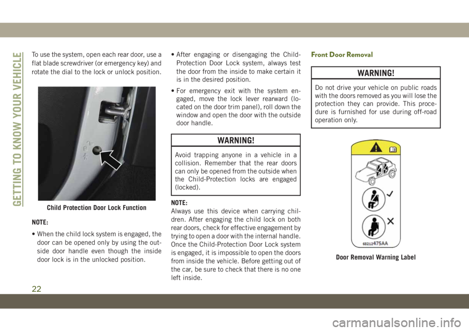
To use the system, open each rear door, use a
flat blade screwdriver (or emergency key) and
rotate the dial to the lock or unlock position.
NOTE:
• When the child lock system is engaged, the
door can be opened only by using the out-
side door handle even though the inside
door lock is in the unlocked position.• After engaging or disengaging the Child-
Protection Door Lock system, always test
the door from the inside to make certain it
is in the desired position.
• For emergency exit with the system en-
gaged, move the lock lever rearward (lo-
cated on the door trim panel), roll down the
window and open the door with the outside
door handle.
WARNING!
Avoid trapping anyone in a vehicle in a
collision. Remember that the rear doors
can only be opened from the outside when
the Child-Protection locks are engaged
(locked).
NOTE:
Always use this device when carrying chil-
dren. After engaging the child lock on both
rear doors, check for effective engagement by
trying to open a door with the internal handle.
Once the Child-Protection Door Lock system
is engaged, it is impossible to open the doors
from inside the vehicle. Before getting out of
the car, be sure to check that there is no one
left inside.
Front Door Removal
WARNING!
Do not drive your vehicle on public roads
with the doors removed as you will lose the
protection they can provide. This proce-
dure is furnished for use during off-road
operation only.
Child Protection Door Lock Function
Door Removal Warning Label
GETTING TO KNOW YOUR VEHICLE
22
Page 25 of 348
WARNING!
• All occupants must wear seat belts dur-
ing off-road operation with doors re-
moved. Refer to “Off-Road Driving Tips”
in “Starting And Operating” in the Own-
er’s Manual for further information.
• Do not store detached doors inside of the
vehicle, as they may cause personal in-
jury in the event of an accident.
NOTE:
•Doors are heavy; use caution when removing
them.
•Hinge pin can break if overtightened during
door reinstall (Max Torque: 7.5 ft· lb /
10 N·m). Refer to “Off-Road Driving Tips” in
“Starting And Operating” in the Owner’s
Manual for further information.
1. Roll down the glass window to prevent any
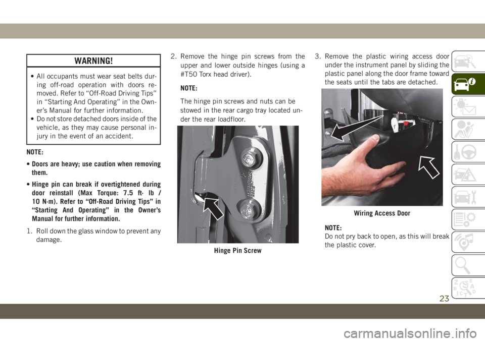
damage.2. Remove the hinge pin screws from the
upper and lower outside hinges (using a
#T50 Torx head driver).
NOTE:
The hinge pin screws and nuts can be
stowed in the rear cargo tray located un-
der the rear loadfloor.3. Remove the plastic wiring access door
under the instrument panel by sliding the
plastic panel along the door frame toward
the seats until the tabs are detached.
NOTE:
Do not pry back to open, as this will break
the plastic cover.
Hinge Pin Screw
Wiring Access Door
23
Page 26 of 348
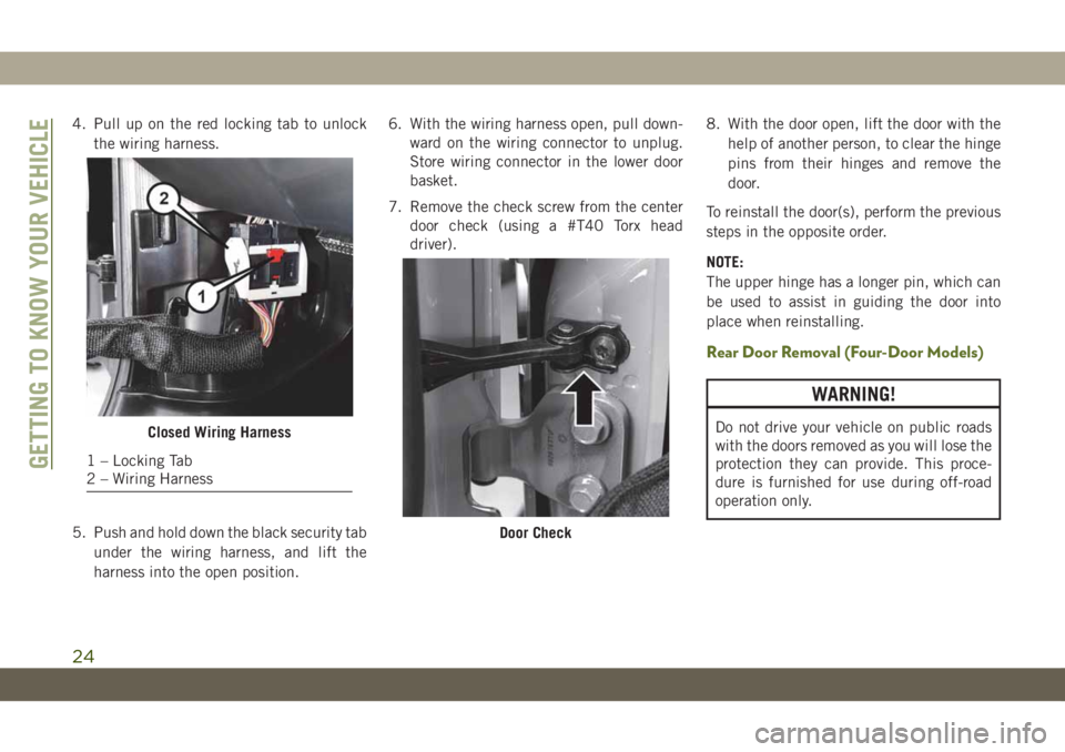
4. Pull up on the red locking tab to unlock
the wiring harness.
5. Push and hold down the black security tab
under the wiring harness, and lift the
harness into the open position.6. With the wiring harness open, pull down-
ward on the wiring connector to unplug.
Store wiring connector in the lower door
basket.
7. Remove the check screw from the center
door check (using a #T40 Torx head
driver).8. With the door open, lift the door with the
help of another person, to clear the hinge
pins from their hinges and remove the
door.
To reinstall the door(s), perform the previous
steps in the opposite order.
NOTE:
The upper hinge has a longer pin, which can
be used to assist in guiding the door into
place when reinstalling.
Rear Door Removal (Four-Door Models)
WARNING!
Do not drive your vehicle on public roads
with the doors removed as you will lose the
protection they can provide. This proce-
dure is furnished for use during off-road
operation only.Closed Wiring Harness
1 – Locking Tab
2 – Wiring Harness
Door Check
GETTING TO KNOW YOUR VEHICLE
24