ENGINE WARNING LIGHTS JEEP WRANGLER UNLIMITED 2018 Owner handbook (in English)
[x] Cancel search | Manufacturer: JEEP, Model Year: 2018, Model line: WRANGLER UNLIMITED, Model: JEEP WRANGLER UNLIMITED 2018Pages: 348, PDF Size: 6.5 MB
Page 16 of 348
NOTE:
A low key fob battery condition may be indi-
cated by a message in the instrument cluster
display, or by the LED light on the key fob. If
the LED key fob light no longer illuminates
from key fob button pushes, then the key fob
battery requires replacement.
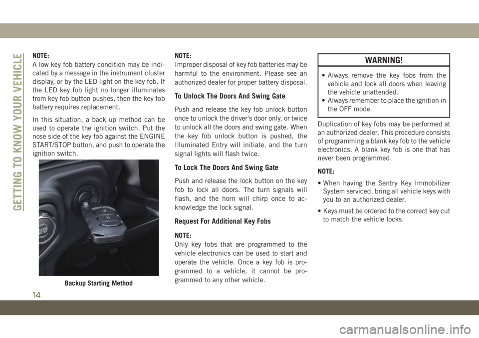
In this situation, a back up method can be
used to operate the ignition switch. Put the
nose side of the key fob against the ENGINE
START/STOP button, and push to operate the
ignition switch.NOTE:
Improper disposal of key fob batteries may be
harmful to the environment. Please see an
authorized dealer for proper battery disposal.
To Unlock The Doors And Swing Gate
Push and release the key fob unlock button
once to unlock the driver's door only, or twice
to unlock all the doors and swing gate. When
the key fob unlock button is pushed, the
Illuminated Entry will initiate, and the turn
signal lights will flash twice.
To Lock The Doors And Swing Gate
Push and release the lock button on the key
fob to lock all doors. The turn signals will
flash, and the horn will chirp once to ac-
knowledge the lock signal.
Request For Additional Key Fobs
NOTE:
Only key fobs that are programmed to the
vehicle electronics can be used to start and
operate the vehicle. Once a key fob is pro-
grammed to a vehicle, it cannot be pro-
grammed to any other vehicle.
WARNING!
• Always remove the key fobs from the
vehicle and lock all doors when leaving
the vehicle unattended.
• Always remember to place the ignition in
the OFF mode.
Duplication of key fobs may be performed at
an authorized dealer. This procedure consists
of programming a blank key fob to the vehicle
electronics. A blank key fob is one that has
never been programmed.
NOTE:
• When having the Sentry Key Immobilizer
System serviced, bring all vehicle keys with
you to an authorized dealer.
• Keys must be ordered to the correct key cut
to match the vehicle locks.
Backup Starting Method
GETTING TO KNOW YOUR VEHICLE
14
Page 61 of 348
CAUTION!
life and/or prevent the engine from start-
ing.
• Accessories that draw higher power (i.e.,
coolers, vacuum cleaners, lights, etc.),
will degrade the battery even more
quickly. Only use these intermittently
and with greater caution.
• After the use of high power draw acces-
sories, or long periods of the vehicle not
being started (with accessories still
plugged in), the vehicle must be driven a
sufficient length of time to allow the
alternator to recharge the vehicle's bat-
tery.
• Power outlets are designed for accessory
plugs only. Do not hang any type of
accessory or accessory bracket from the
plug. Improper use of the power outlet
can cause damage.
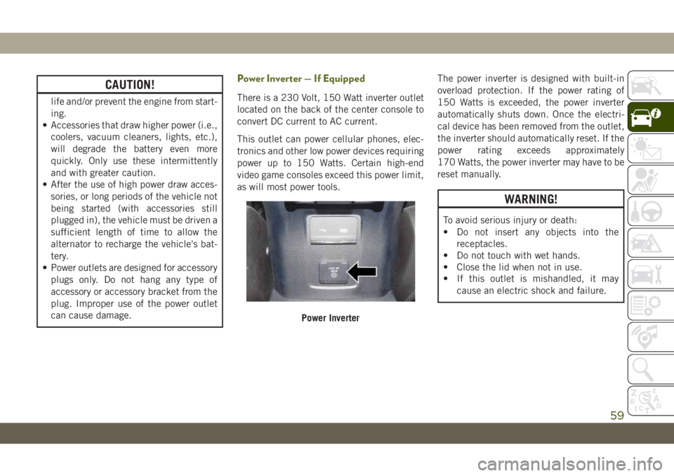
Power Inverter — If Equipped
There is a 230 Volt, 150 Watt inverter outlet
located on the back of the center console to
convert DC current to AC current.
This outlet can power cellular phones, elec-
tronics and other low power devices requiring
power up to 150 Watts. Certain high-end
video game consoles exceed this power limit,
as will most power tools.The power inverter is designed with built-in
overload protection. If the power rating of
150 Watts is exceeded, the power inverter
automatically shuts down. Once the electri-
cal device has been removed from the outlet,
the inverter should automatically reset. If the
power rating exceeds approximately
170 Watts, the power inverter may have to be
reset manually.
WARNING!
To avoid serious injury or death:
• Do not insert any objects into the
receptacles.
• Do not touch with wet hands.
• Close the lid when not in use.
• If this outlet is mishandled, it may
cause an electric shock and failure.
Power Inverter
59
Page 62 of 348
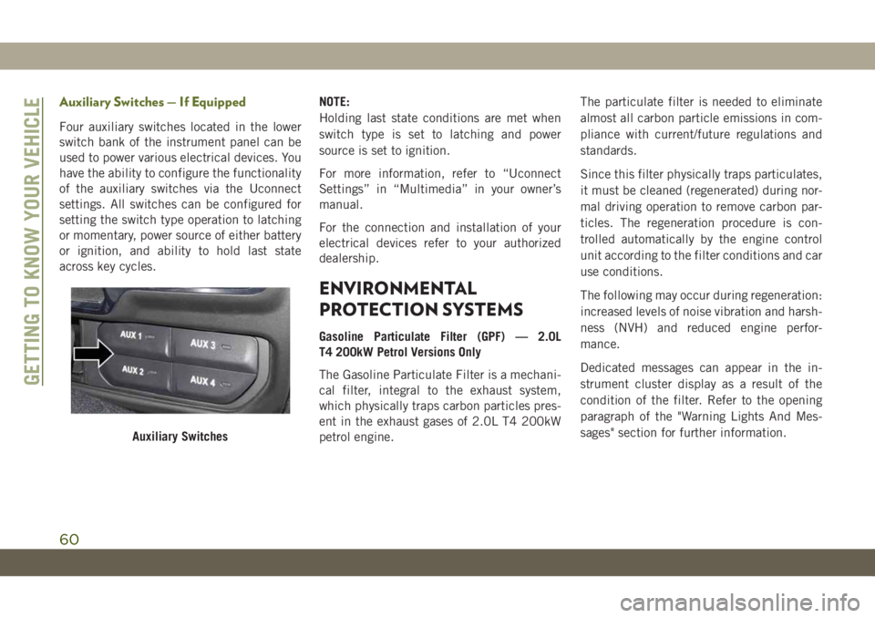
Auxiliary Switches — If Equipped
Four auxiliary switches located in the lower
switch bank of the instrument panel can be
used to power various electrical devices. You
have the ability to configure the functionality
of the auxiliary switches via the Uconnect
settings. All switches can be configured for
setting the switch type operation to latching
or momentary, power source of either battery
or ignition, and ability to hold last state
across key cycles.NOTE:
Holding last state conditions are met when
switch type is set to latching and power
source is set to ignition.
For more information, refer to “Uconnect
Settings” in “Multimedia” in your owner’s
manual.
For the connection and installation of your
electrical devices refer to your authorized
dealership.
ENVIRONMENTAL
PROTECTION SYSTEMS
Gasoline Particulate Filter (GPF) — 2.0L
T4 200kW Petrol Versions Only
The Gasoline Particulate Filter is a mechani-
cal filter, integral to the exhaust system,
which physically traps carbon particles pres-
ent in the exhaust gases of 2.0L T4 200kW
petrol engine.The particulate filter is needed to eliminate
almost all carbon particle emissions in com-
pliance with current/future regulations and
standards.
Since this filter physically traps particulates,
it must be cleaned (regenerated) during nor-
mal driving operation to remove carbon par-
ticles. The regeneration procedure is con-
trolled automatically by the engine control
unit according to the filter conditions and car
use conditions.
The following may occur during regeneration:
increased levels of noise vibration and harsh-
ness (NVH) and reduced engine perfor-
mance.
Dedicated messages can appear in the in-
strument cluster display as a result of the
condition of the filter. Refer to the opening
paragraph of the "Warning Lights And Mes-
sages" section for further information.
Auxiliary Switches
GETTING TO KNOW YOUR VEHICLE
60
Page 68 of 348
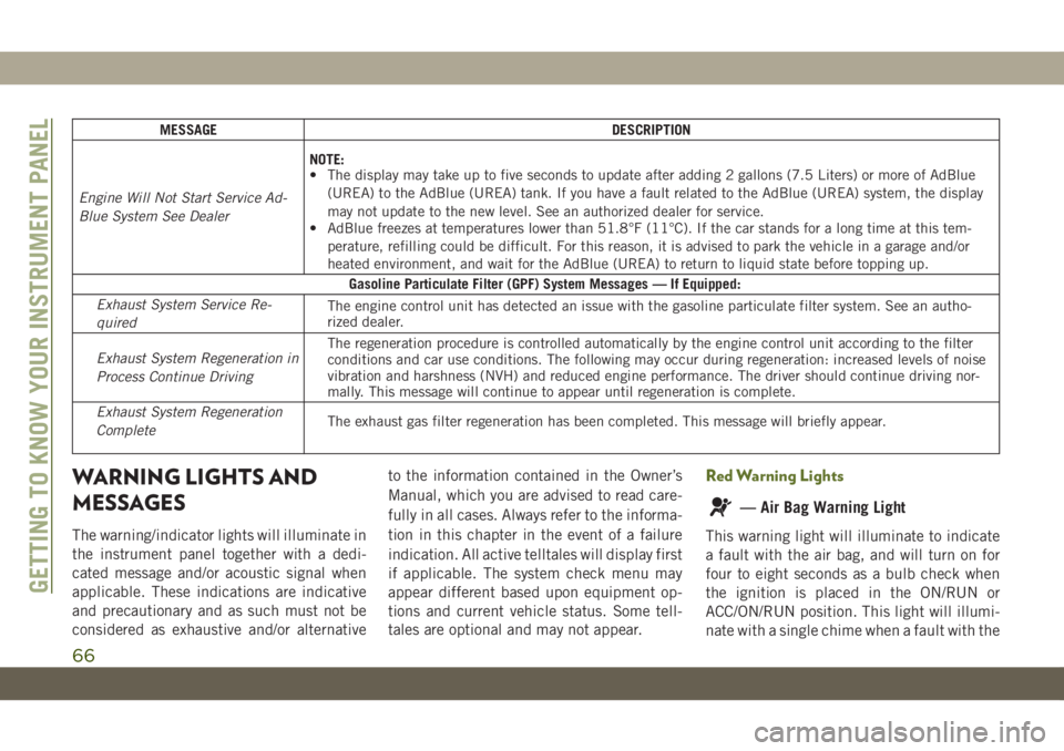
MESSAGE DESCRIPTION
Engine Will Not Start Service Ad-
Blue System See DealerNOTE:
• The display may take up to five seconds to update after adding 2 gallons (7.5 Liters) or more of AdBlue
(UREA) to the AdBlue (UREA) tank. If you have a fault related to the AdBlue (UREA) system, the display
may not update to the new level. See an authorized dealer for service.
• AdBlue freezes at temperatures lower than 51.8°F (11°C). If the car stands for a long time at this tem-
perature, refilling could be difficult. For this reason, it is advised to park the vehicle in a garage and/or
heated environment, and wait for the AdBlue (UREA) to return to liquid state before topping up.
Gasoline Particulate Filter (GPF) System Messages — If Equipped:
Exhaust System Service Re-
quiredThe engine control unit has detected an issue with the gasoline particulate filter system. See an autho-
rized dealer.
Exhaust System Regeneration in
Process Continue DrivingThe regeneration procedure is controlled automatically by the engine control unit according to the filter
conditions and car use conditions. The following may occur during regeneration: increased levels of noise
vibration and harshness (NVH) and reduced engine performance. The driver should continue driving nor-
mally. This message will continue to appear until regeneration is complete.
Exhaust System Regeneration
CompleteThe exhaust gas filter regeneration has been completed. This message will briefly appear.
WARNING LIGHTS AND
MESSAGES
The warning/indicator lights will illuminate in
the instrument panel together with a dedi-
cated message and/or acoustic signal when
applicable. These indications are indicative
and precautionary and as such must not be
considered as exhaustive and/or alternativeto the information contained in the Owner’s
Manual, which you are advised to read care-
fully in all cases. Always refer to the informa-
tion in this chapter in the event of a failure
indication. All active telltales will display first
if applicable. The system check menu may
appear different based upon equipment op-
tions and current vehicle status. Some tell-
tales are optional and may not appear.
Red Warning Lights
— Air Bag Warning Light
This warning light will illuminate to indicate
a fault with the air bag, and will turn on for
four to eight seconds as a bulb check when
the ignition is placed in the ON/RUN or
ACC/ON/RUN position. This light will illumi-
nate with a single chime when a fault with the
GETTING TO KNOW YOUR INSTRUMENT PANEL
66
Page 72 of 348
vehicle and run the engine at idle or slightly
faster, with the transmission in PARK or
NEUTRAL, until the light turns off. Once the
light turns off, you may continue to drive
normally.
WARNING!
If you continue operating the vehicle when
the Transmission Temperature Warning
Light is illuminated you could cause the
fluid to boil over, come in contact with hot
engine or exhaust components and cause
a fire.
CAUTION!
Continuous driving with the Transmission
Temperature Warning Light illuminated
will eventually cause severe transmission
damage or transmission failure.
— Vehicle Security Warning Light — If
Equipped
This light will flash at a fast rate for approxi-
mately 15 seconds when the vehicle security
alarm is arming, and then will flash slowly
until the vehicle is disarmed.
Yellow Warning Lights
— Anti-Lock Brake (ABS) Warning
Light
This warning light monitors the Anti-Lock
Brake System (ABS). The light will turn on
when the ignition is placed in the ON/RUN or
ACC/ON/RUN position and may stay on for as
long as four seconds.
If the ABS light remains on or turns on while
driving, then the Anti-Lock portion of the
brake system is not functioning and service is
required as soon as possible. However, the
conventional brake system will continue to
operate normally, assuming the Brake Warn-
ing Light is not also on.If the ABS light does not turn on when the
ignition is placed in the ON/RUN or ACC/ON/
RUN position, have the brake system in-
spected by an authorized dealer.
— Electronic Stability Control (ESC)
Active Warning Light — If Equipped
This warning light will indicate when the
Electronic Stability Control system is Active.
The “ESC Indicator Light” in the instrument
cluster will come on when the ignition is
placed in the ON/RUN or ACC/ON/RUN posi-
tion, and when ESC is activated. It should go
out with the engine running. If the “ESC
Indicator Light” comes on continuously with
the engine running, a malfunction has been
detected in the ESC system. If this warning
light remains on after several ignition cycles,
and the vehicle has been driven several miles
(kilometers) at speeds greater than 30 mph
(48 km/h), see an authorized dealer as soon
as possible to have the problem diagnosed
and corrected.
• The “ESC Off Indicator Light” and the
“ESC Indicator Light” come on momen-
tarily each time the ignition is placed in the
ON/RUN or ACC/ON/RUN position.
GETTING TO KNOW YOUR INSTRUMENT PANEL
70
Page 76 of 348
Yellow Indicator Lights
/— 4WD Indicator Light — If
Equipped
This light alerts the driver that the vehicle is
in the four-wheel drive mode, and the front
and rear driveshafts are mechanically locked
together forcing the front and rear wheels to
rotate at the same speed.
4L/4WD
LOW— 4WD Low Indicator Light — If
Equipped
This light alerts the driver that the vehicle is
in the four-wheel drive LOW mode. The front
and rear driveshafts are mechanically locked
together forcing the front and rear wheels to
rotate at the same speed. Low range provides
a greater gear reduction ratio to provide in-
creased torque at the wheels.
4HPART
TIME/4WD
PART
TIME—4WD Part Time Indicator Light —
If Equipped
This light alerts the driver that the vehicle is
in the four-wheel drive part time mode, and
the front and rear driveshafts are mechani-
cally locked together forcing the front and
rear wheels to rotate at the same speed.
— Active Speed Limiter Fault Indica-
tor Light — If Equipped
This warning light will illuminate to signal
when there is a fault detected with the Active
Speed Limiter.
— Axle Locker Fault Indicator Light
This light indicates when the front and/or rear
axle locker fault has been detected.
— Front And Rear Axle Lock Indicator
Light
This light indicates when the front, rear, or
both axles have been locked. The telltale will
display the lock icon on the front and rear
axles to indicate the current lock status.
N/NEUTRAL— Neutral Indicator Light
— If Equipped
This light alerts the driver that the vehicle is
in the neutral mode.
— Rear Axle Lock Indicator Light
This light indicates when the rear axle lock
has been activated.
— Rear Fog Indicator — If Equipped
This indicator light will illuminate when the
rear fog lights are on.
— Sway Bar Indicator Light — If
Equipped
This indicator light will illuminate when the
front sway bar is disconnected.
— Wait To Start Light — If Equipped
This indicator light will illuminate for ap-
proximately two seconds when the ignition is
turned to the RUN position. Its duration may
be longer based on colder operating condi-
tions. Vehicle will not initiate start until tell-
tale is no longer displayed.
Refer to “Starting The Engine” in “Starting
And Operating” for further information.
NOTE:
The “Wait To Start” telltale may not illumi-
nate if the intake manifold temperature is
warm enough.
GETTING TO KNOW YOUR INSTRUMENT PANEL
74
Page 80 of 348
Gray Indicator Lights
— Cruise Control Ready Indicator
Light — If Equipped With Base Instrument
Cluster
This light will turn on when the speed control
has been turned on, but not set. Refer to
“Speed Control — If Equipped” in “Starting
And Operating” for further information.
— Active Speed Limiter Ready Indica-
tor Light — If Equipped With A Base Instru-
ment Cluster
This light will turn on when the Active Speed
Limiter is on, but not set.
ONBOARD DIAGNOSTIC
SYSTEM — OBD II
Your vehicle is equipped with a sophisticated
Onboard Diagnostic system called OBD II.
This system monitors the performance of the
emissions, engine, and transmission control
systems. When these systems are operatingproperly, your vehicle will provide excellent
performance and fuel economy, as well as
engine emissions well within current govern-
ment regulations.
If any of these systems require service, the
OBD II system will turn on the Malfunction
Indicator Light (MIL). It will also store diag-
nostic codes and other information to assist
your service technician in making repairs.
Although your vehicle will usually be drivable
and not need towing, see an authorized
dealer for service as soon as possible.
CAUTION!
• Prolonged driving with the MIL on could
cause further damage to the emission
control system. It could also affect fuel
economy and driveability. The vehicle
must be serviced before any emissions
tests can be performed.
• If the MIL is flashing while the vehicle is
running, severe catalytic converter dam-
age and power loss will soon occur. Im-
mediate service is required.
Onboard Diagnostic System (OBD II)
Cybersecurity
Your vehicle is required to have an Onboard
Diagnostic system (OBD II) and a connection
port to allow access to information related to
the performance of your emissions controls.
Authorized service technicians may need to
access this information to assist with the
diagnosis and service of your vehicle and
emissions system.
WARNING!
• ONLY an authorized service technician
should connect equipment to the OBD II
connection port in order to read the VIN,
diagnose, or service your vehicle.
• If unauthorized equipment is connected
to the OBD II connection port, such as a
driver-behavior tracking device, it may:
• Be possible that vehicle systems,
including safety related systems,
could be impaired or a loss of ve-
hicle control could occur that may
result in an accident involving seri-
ous injury or death.
GETTING TO KNOW YOUR INSTRUMENT PANEL
78
Page 121 of 348
• As the air bags deflate, you may see some
smoke-like particles. The particles are a
normal by-product of the process that gen-
erates the non-toxic gas used for air bag
inflation. These airborne particles may irri-
tate the skin, eyes, nose, or throat. If you
have skin or eye irritation, rinse the area
with cool water. For nose or throat irritation,
move to fresh air. If the irritation continues,
see your doctor. If these particles settle on
your clothing, follow the garment manufac-
turer’s instructions for cleaning.
Do not drive your vehicle after the air bags
have deployed. If you are involved in another
collision, the air bags will not be in place to
protect you.
WARNING!
Deployed air bags and seat belt preten-
sioners cannot protect you in another col-
lision. Have the air bags, seat belt preten-
sioners, and the seat belt retractor
assemblies replaced by an authorized
dealer immediately. Also, have the Occu-
pant Restraint Controller System serviced
as well.NOTE:
• Air bag covers may not be obvious in the
interior trim, but they will open during air
bag deployment.
• After any collision, the vehicle should be
taken to an authorized dealer immediately.
Enhanced Accident Response System
In the event of an impact, if the communica-
tion network remains intact, and the power
remains intact, depending on the nature of
the event, the ORC will determine whether to
have the Enhanced Accident Response Sys-
tem perform the following functions:
• Cut off fuel to the engine (If Equipped)
• Cut off battery power to the electric motor
(If Equipped)
• Flash hazard lights as long as the battery
has power
• Turn on the interior lights, which remain on
as long as the battery has power or for 15
minutes from the intervention of the En-
hanced Accident Response System.
• Unlock the power door locks.Your vehicle may also be designed to perform
any of these other functions in response to
the Enhanced Accident Response System:
• Turn off the Fuel Filter Heater, Turn off the
HVAC Blower Motor, Close the HVAC Circu-
lation Door
• Cut off battery power to the:
– Engine
– Electric Motor (if equipped)
– Electric power steering
– Brake booster
– Electric park brake
– Automatic transmission gear selector
– Horn
– Front wiper
– Headlamp washer pump
NOTE:
After an accident, remember to cycle the
ignition to the STOP (OFF/LOCK) position
and remove the key from the ignition switch
to avoid draining the battery. Carefully check
the vehicle for fuel leaks in the engine com-
partment and on the ground near the engine
compartment and fuel tank before resetting
the system and starting the engine. If there
are no fuel leaks or damage to the vehicle
119
Page 122 of 348

electrical devices (e.g. headlights) after an
accident, reset the system by following the
procedure described below. If you have any
doubt, contact an authorized dealer.
Enhanced Accident Response System Reset
Procedure
In order to reset the Enhanced Accident Re-
sponse System functions after an event, the
ignition switch must be changed from igni-
tion START or ON/RUN to ignition OFF. Care-
fully check the vehicle for fuel leaks in the
engine compartment and on the ground near
the engine compartment and fuel tank before
resetting the system and starting the engine.
Maintaining Your Air Bag System
WARNING!
• Modifications to any part of the air bag
system could cause it to fail when you
need it. You could be injured if the air
bag system is not there to protect you.
Do not modify the components or wiring,
including adding any kind of badges or
stickers to the steering wheel hub trim
WARNING!
cover or the upper passenger side of the
instrument panel. Do not modify the
front bumper, vehicle body structure, or
add aftermarket side steps or running
boards.
• It is dangerous to try to repair any part of
the air bag system yourself. Be sure to
tell anyone who works on your vehicle
that it has an air bag system.
• Do not attempt to modify any part of your
air bag system. The air bag may inflate
accidentally or may not function prop-
erly if modifications are made. Take your
vehicle to an authorized dealer for any
air bag system service. If your seat, in-
cluding your trim cover and cushion,
needs to be serviced in any way (includ-
ing removal or loosening/tightening of
seat attachment bolts), take the vehicle
to an authorized dealer. Only manufac-
turer approved seat accessories may be
used. If it is necessary to modify the air
bag system for persons with disabilities,
contact an authorized dealer.
Event Data Recorder (EDR)
This vehicle is equipped with an event data
recorder (EDR). The main purpose of an EDR
is to record, in certain crash or near crash-
like situations, such as an air bag deployment
or hitting a road obstacle, data that will assist
in understanding how a vehicle’s systems
performed. The EDR is designed to record
data related to vehicle dynamics and safety
systems for a short period of time, typically
30 seconds or less. The EDR in this vehicle is
designed to record such data as:
• How various systems in your vehicle were
operating;
• Whether or not the driver and passenger
safety belts were buckled/fastened;
• How far (if at all) the driver was depressing
the accelerator and/or brake pedal; and,
• How fast the vehicle was traveling.
These data can help provide a better under-
standing of the circumstances in which
crashes and injuries occur.
SAFETY
120
Page 170 of 348
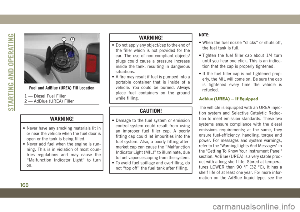
WARNING!
• Never have any smoking materials lit in
or near the vehicle when the fuel door is
open or the tank is being filled.
• Never add fuel when the engine is run-
ning. This is in violation of most coun-
tries regulations and may cause the
“Malfunction Indicator Light” to turn
on.
WARNING!
• Do not apply any object/cap to the end of
the filler which is not provided for the
car. The use of non-compliant objects/
plugs could cause a pressure increase
inside the tank, resulting in dangerous
situations.
• A fire may result if fuel is pumped into a
portable container that is inside of a
vehicle. You could be burned. Always
place fuel containers on the ground
while filling.
CAUTION!
• Damage to the fuel system or emission
control system could result from using
an improper fuel filler cap. A poorly
fitting cap could let impurities into the
fuel system. Also, a poorly fitting after-
market cap can cause the “Malfunction
Indicator Light (MIL)” to illuminate, due
to fuel vapors escaping from the system.
• To avoid fuel spillage and overfilling, do
not “top off” the fuel tank after filling.NOTE:
• When the fuel nozzle “clicks” or shuts off,
the fuel tank is full.
• Tighten the fuel filler cap about 1/4 turn
until you hear one click. This is an indica-
tion that the cap is properly tightened.
• If the fuel filler cap is not tightened prop-
erly, the MIL will come on. Be sure the cap
is tightened every time the vehicle is
refueled.
Adblue (UREA) — If Equipped
The vehicle is equipped with an UREA injec-
tion system and Selective Catalytic Reduc-
tion to meet emission standards. These two
systems ensure compliance with the diesel
emissions requirements; at the same, they
ensure fuel-efficiency, handling, torque and
power. For messages and system warnings,
refer to the "Warning Lights And Messages" in
the "Getting To Know Your Instrument Panel"
section. AdBlue (UREA) is a very stable prod-
uct with a long shelf life. Stored at tempera-
tures LOWER than 90 °F (32 °C), it has a
shelf life of at least one year. For more infor-
mation on the AdBlue liquid type, see the
Fuel and AdBlue (UREA) Fill Location
1 — Diesel Fuel Filler
2 — AdBlue (UREA) Filler
STARTING AND OPERATING
168