climate control JEEP WRANGLER UNLIMITED 2019 Owner handbook (in English)
[x] Cancel search | Manufacturer: JEEP, Model Year: 2019, Model line: WRANGLER UNLIMITED, Model: JEEP WRANGLER UNLIMITED 2019Pages: 348, PDF Size: 6.5 MB
Page 45 of 348
Icon Description
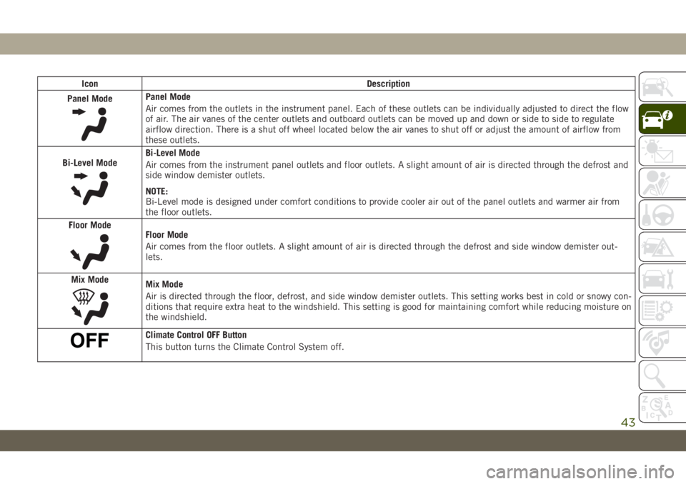
Panel Mode
Panel Mode
Air comes from the outlets in the instrument panel. Each of these outlets can be individually adjusted to direct the flow
of air. The air vanes of the center outlets and outboard outlets can be moved up and down or side to side to regulate
airflow direction. There is a shut off wheel located below the air vanes to shut off or adjust the amount of airflow from
these outlets.
Bi-Level Mode
Bi-Level Mode
Air comes from the instrument panel outlets and floor outlets. A slight amount of air is directed through the defrost and
side window demister outlets.
NOTE:
Bi-Level mode is designed under comfort conditions to provide cooler air out of the panel outlets and warmer air from
the floor outlets.
Floor Mode
Floor Mode
Air comes from the floor outlets. A slight amount of air is directed through the defrost and side window demister out-
lets.
Mix Mode
Mix Mode
Air is directed through the floor, defrost, and side window demister outlets. This setting works best in cold or snowy con-
ditions that require extra heat to the windshield. This setting is good for maintaining comfort while reducing moisture on
the windshield.
Climate Control OFF Button
This button turns the Climate Control System off.
43
Page 46 of 348
Climate Control Functions
Air Conditioning (A/C)
The Air Conditioning (A/C) button allows the
operator to turn the air conditioning system
on and off. When the system is turned on,
cool dehumidified air flows through the vents
into the cabin.
For improved fuel economy, press the A/C
button to turn off the air conditioning off and
adjust the blower and airflow mode settings.
Make sure to only select Panel, Bi-Level, or
Floor modes.
NOTE:
• If fog or mist appears on the windshield or
windows, select Defrost mode and increase
the blower speed.
• If the air conditioning performance is lower
than expected, there maybe blockage. Gen-
tly clean the area around the radiator with
water.
MAX A/C
The MAX A/C setting provides the maximum
cooling performance.Press the button to toggle between MAX A/C
and your prior setting. The button illuminates
when MAX A/C is on.
In the MAX A/C setting, you can adjust the
blower level and mode position. Pressing
other settings causes the MAX A/C operation
to switch to your desired setting.
Recirculation
In cold weather, use of Recirculation mode
may lead to excessive window fogging. The
Recirculation feature may be unavailable
(button on the touchscreen greyed out) if
conditions exist that could create fogging on
the inside of the windshield.
Automatic Temperature Control (ATC) —
If Equipped
Automatic Operation
1. Push the AUTO button on the faceplate,
or the AUTO button on the touchscreen on
the Automatic Temperature Control (ATC)
Panel.
2. Next, adjust the temperature you would
like the system to maintain by adjusting
the driver and passenger temperaturecontrol buttons. Once the desired tem-
perature is displayed, the system will
achieve and automatically maintain that
comfort level.
3. When the system is set up for your comfort
level, it is not necessary to change the
settings. You will experience the greatest
efficiency by simply allowing the system
to function automatically.
NOTE:
• It is not necessary to move the temperature
settings for cold or hot vehicles. The system
automatically adjusts the temperature,
mode, and blower speed to provide comfort
as quickly as possible.
• The temperature can be displayed in U.S.
or Metric units by selecting the US/Metric
customer-programmable feature. Refer to
the “Uconnect Settings” in “Multimedia”
in your Owner’s Manual for further
information.
To provide you with maximum comfort in the
Automatic mode during cold start-ups, the
blower fan will remain on low until the engine
warms up. The blower will increase in speed
and transition into Auto mode.
GETTING TO KNOW YOUR VEHICLE
44
Page 47 of 348
Manual Operation Override
This system offers a full complement of
manual override features. The AUTO symbol
in the front ATC display will be turned off
when the system is being used in the manual
mode.
Operating Tips
Summer Operation
The engine cooling system must be protected
with a high-quality antifreeze coolant to pro-
vide proper corrosion protection and to pro-
tect against engine overheating. OAT coolant
(conforming to MS.90032) is recommended.
Winter Operation
To ensure the best possible heater and de-
froster performance, make sure the engine
cooling system is functioning properly and
the proper amount, type, and concentration
of coolant is used. Use of the Air Recircula-
tion mode during Winter months is not rec-
ommended, because it may cause window
fogging.
Vacation/Storage
Before you store your vehicle, or keep it out of
service (i.e., vacation) for two weeks or more,
run the air conditioning system at idle for
about five minutes, in fresh air with the
blower setting on high. This will ensure ad-
equate system lubrication to minimize the
possibility of compressor damage when the
system is started again.
Window Fogging
Vehicle windows tend to fog on the inside in
mild, rainy, and/or humid weather. To clear
the windows, select Defrost or Mix mode and
increase the front blower speed. Do not use
the Recirculation mode without A/C for long
periods, as fogging may occur.
CAUTION!
Failure to follow these cautions can cause
damage to the heating elements:
• Use care when washing the inside of
the rear window. Do not use abrasive
window cleaners on the interior surface
of the window. Use a soft cloth and a
CAUTION!
mild washing solution, wiping parallel
to the heating elements. Labels can be
peeled off after soaking with warm
water.
• Do not use scrapers, sharp instru-
ments, or abrasive window cleaners on
the interior surface of the window.
• Keep all objects a safe distance from
the window.
Outside Air Intake
Make sure the air intake, located directly in
front of the windshield, is free of obstruc-
tions, such as leaves. Leaves collected in the
air intake may reduce airflow, and if they
enter the plenum, they could plug the water
drains. In Winter months, make sure the air
intake is clear of ice, slush, and snow.
Cabin Air Filter
The climate control system filters out dust
and pollen from the air. Contact an autho-
rized dealer to service your cabin air filter,
and to have it replaced when needed.
45
Page 48 of 348
POWER WINDOWS — IF
EQUIPPED
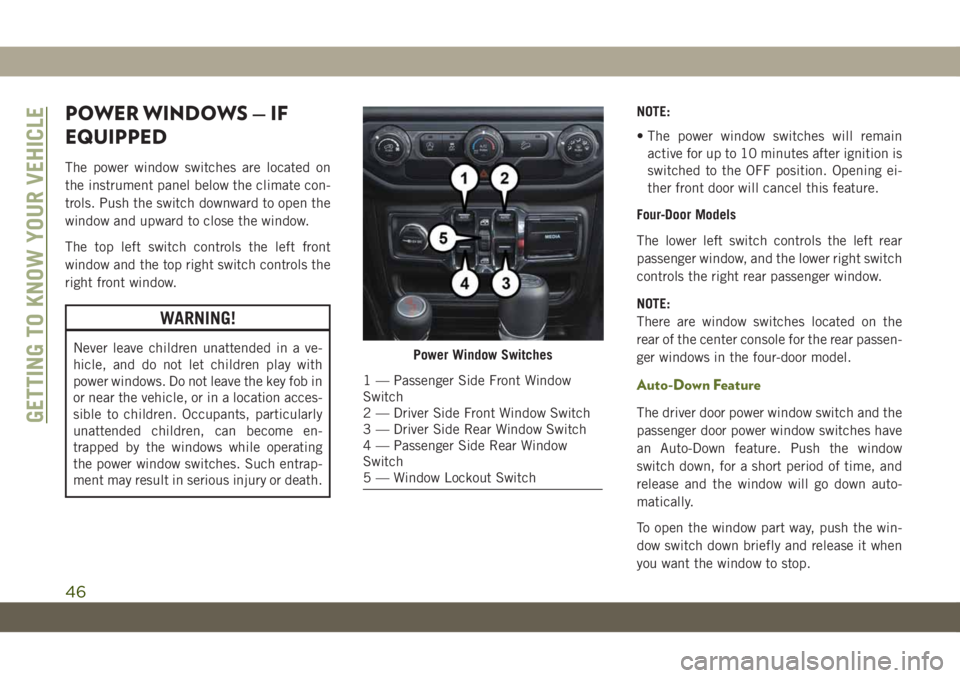
The power window switches are located on
the instrument panel below the climate con-
trols. Push the switch downward to open the
window and upward to close the window.
The top left switch controls the left front
window and the top right switch controls the
right front window.
WARNING!
Never leave children unattended in a ve-
hicle, and do not let children play with
power windows. Do not leave the key fob in
or near the vehicle, or in a location acces-
sible to children. Occupants, particularly
unattended children, can become en-
trapped by the windows while operating
the power window switches. Such entrap-
ment may result in serious injury or death.NOTE:
• The power window switches will remain
active for up to 10 minutes after ignition is
switched to the OFF position. Opening ei-
ther front door will cancel this feature.
Four-Door Models
The lower left switch controls the left rear
passenger window, and the lower right switch
controls the right rear passenger window.
NOTE:
There are window switches located on the
rear of the center console for the rear passen-
ger windows in the four-door model.
Auto-Down Feature
The driver door power window switch and the
passenger door power window switches have
an Auto-Down feature. Push the window
switch down, for a short period of time, and
release and the window will go down auto-
matically.
To open the window part way, push the win-
dow switch down briefly and release it when
you want the window to stop.
Power Window Switches
1 — Passenger Side Front Window
Switch
2 — Driver Side Front Window Switch
3 — Driver Side Rear Window Switch
4 — Passenger Side Rear Window
Switch
5 — Window Lockout Switch
GETTING TO KNOW YOUR VEHICLE
46
Page 60 of 348
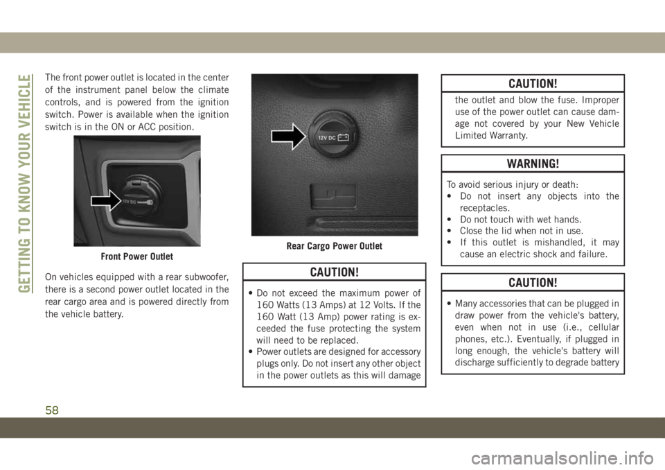
The front power outlet is located in the center
of the instrument panel below the climate
controls, and is powered from the ignition
switch. Power is available when the ignition
switch is in the ON or ACC position.
On vehicles equipped with a rear subwoofer,
there is a second power outlet located in the
rear cargo area and is powered directly from
the vehicle battery.
CAUTION!
• Do not exceed the maximum power of
160 Watts (13 Amps) at 12 Volts. If the
160 Watt (13 Amp) power rating is ex-
ceeded the fuse protecting the system
will need to be replaced.
• Power outlets are designed for accessory
plugs only. Do not insert any other object
in the power outlets as this will damage
CAUTION!
the outlet and blow the fuse. Improper
use of the power outlet can cause dam-
age not covered by your New Vehicle
Limited Warranty.
WARNING!
To avoid serious injury or death:
• Do not insert any objects into the
receptacles.
• Do not touch with wet hands.
• Close the lid when not in use.
• If this outlet is mishandled, it may
cause an electric shock and failure.
CAUTION!
• Many accessories that can be plugged in
draw power from the vehicle's battery,
even when not in use (i.e., cellular
phones, etc.). Eventually, if plugged in
long enough, the vehicle's battery will
discharge sufficiently to degrade battery
Front Power OutletRear Cargo Power Outlet
GETTING TO KNOW YOUR VEHICLE
58
Page 165 of 348
Pushing the on/off button or cycling the igni-
tion to OFF, erases the set speed from
memory.
PARKSENSE REAR PARK
ASSIST — IF EQUIPPED
The ParkSense Rear Park Assist system pro-
vides visual and audible indications of the
distance between the rear fascia and a de-
tected obstacle when backing up, e.g. during
a parking maneuver. Refer to “ParkSense
System Usage Precautions” in this section
for limitations of this system and recommen-
dations.
ParkSense will retain the last system state
(enabled or disabled) from the last ignition
cycle when the ignition is changed to the
ON/RUN position.
ParkSense can be active only when the gear
selector is in REVERSE. If ParkSense is en-
abled at this gear selector position, the sys-
tem will remain active until the vehicle speed
is increased to approximately 7 mph
(11 km/h) or above. When in REVERSE and
above the system's operating speed, a warn-ing will appear within the instrument cluster
display indicating the vehicle speed is too
fast. The system will become active again if
the vehicle speed is decreased to speeds less
than approximately 6 mph (9 km/h).
ParkSense Sensors
The four ParkSense sensors, located in the
rear fascia/bumper, monitor the area behind
the vehicle that is within the sensors’ field of
view. The sensors can detect obstacles from
approximately 12 inches (30 cm) up to
79 inches (200 cm) from the rear fascia/
bumper in the horizontal direction, depend-
ing on the location, type and orientation of
the obstacle.
Enabling And Disabling ParkSense
ParkSense can be enabled and disabled with
the ParkSense switch, located on the switch
panel below the climate controls.
When the ParkSense switch is pushed to
disable the system, the instrument cluster
display will show the “PARKSENSE OFF”
message for approximately five seconds. Re-
fer to “Instrument Cluster Display” in “Get-
ting To Know Your Instrument Panel” in yourOwner’s Manual for further information.
When the gear selector is moved to REVERSE
and the system is disabled, the instrument
cluster display will show the “PARKSENSE
OFF” message for as long as the vehicle is in
REVERSE (Not in 4LO).
The ParkSense switch LED will be on when
ParkSense is disabled or requires service.
The ParkSense switch LED will be off when
the system is enabled. If the ParkSense
switch is pushed, and requires service, the
ParkSense switch LED will blink momen-
tarily, and then the LED will be on.
ParkSense System Usage Precautions
NOTE:
• Ensure that the rear bumper is free of snow,
ice, mud, dirt and debris to keep the
ParkSense system operating properly.
• Jackhammers, large trucks, and other vi-
brations could affect the performance of
ParkSense.
163
Page 178 of 348
HAZARD WARNING
FLASHERS
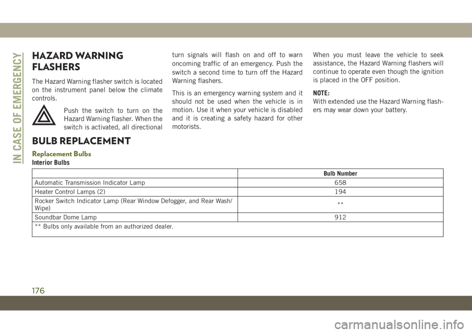
The Hazard Warning flasher switch is located
on the instrument panel below the climate
controls.
Push the switch to turn on the
Hazard Warning flasher. When the
switch is activated, all directionalturn signals will flash on and off to warn
oncoming traffic of an emergency. Push the
switch a second time to turn off the Hazard
Warning flashers.
This is an emergency warning system and it
should not be used when the vehicle is in
motion. Use it when your vehicle is disabled
and it is creating a safety hazard for other
motorists.When you must leave the vehicle to seek
assistance, the Hazard Warning flashers will
continue to operate even though the ignition
is placed in the OFF position.
NOTE:
With extended use the Hazard Warning flash-
ers may wear down your battery.
BULB REPLACEMENT
Replacement Bulbs
Interior Bulbs
Bulb Number
Automatic Transmission Indicator Lamp 658
Heater Control Lamps (2)194
Rocker Switch Indicator Lamp (Rear Window Defogger, and Rear Wash/
Wipe)**
Soundbar Dome Lamp912
** Bulbs only available from an authorized dealer.
IN CASE OF EMERGENCY
176
Page 264 of 348
Component Fluid, Lubricant, or Genuine Part
Brake Master Cylinder We recommend you use DOT 3, SAE J1703 brake fluid. If DOT 3 brake fluid is not available
then TUTELA TOP4/S, FMVSS no. 116 DOT 4, ISO 4925 SAE J1704, or equivalent, is
acceptable.
If using DOT 4 brake fluid, the fluid must be changed every 24 months regardless of mileage.
Power Steering Reservoir We recommend you use TUTELA TRANSMISSION FORCE 4 fluid, or equivalent, meeting
requirement of FCA Material Standard 9.55550-AV4 or MS.9602.
FUEL CONSUMPTION AND
CO
2EMISSIONS
The fuel consumption and CO2emission
figures declared by the manufacturer are de-
termined on the basis of the type-approval
tests laid down by the applicable standards
in the country where the vehicle is registered.
The type of route, traffic conditions, weather
conditions, driving style, general condition of
the vehicle, trim level/equipment/ accesso-
ries, use of the climate control system, ve-
hicle load, presence of roof racks and othersituations that adversely affect the aerody-
namics or wind resistance lead to different
fuel consumption values than those mea-
sured.
The fuel consumption will only become more
regular after driving the first 1,864 miles
(3000 km).
To find the specific fuel consumption and
CO
2emission figures for this vehicle, please
refer to the data in the Certificate of Confor-
mity, and the related documentation that
accompanies the vehicle.
MOPAR ACCESSORIES
Authentic Accessories And Jeep
Performance Parts By Mopar
• Mopar Accessories and Jeep performance
parts are developed with the same engi-
neering that went into your Wrangler.
Choose these products with confidence
knowing that they have passed the same
rigid standards for function, fit, durability
and performance as your Wrangler.
• For the full line of Authentic Jeep Accesso-
ries by Mopar, visit your local dealership or
online at jeep.mopar.eu
NOTE:
All parts are subject to availability.TECHNICAL SPECIFICATIONS
262
Page 291 of 348
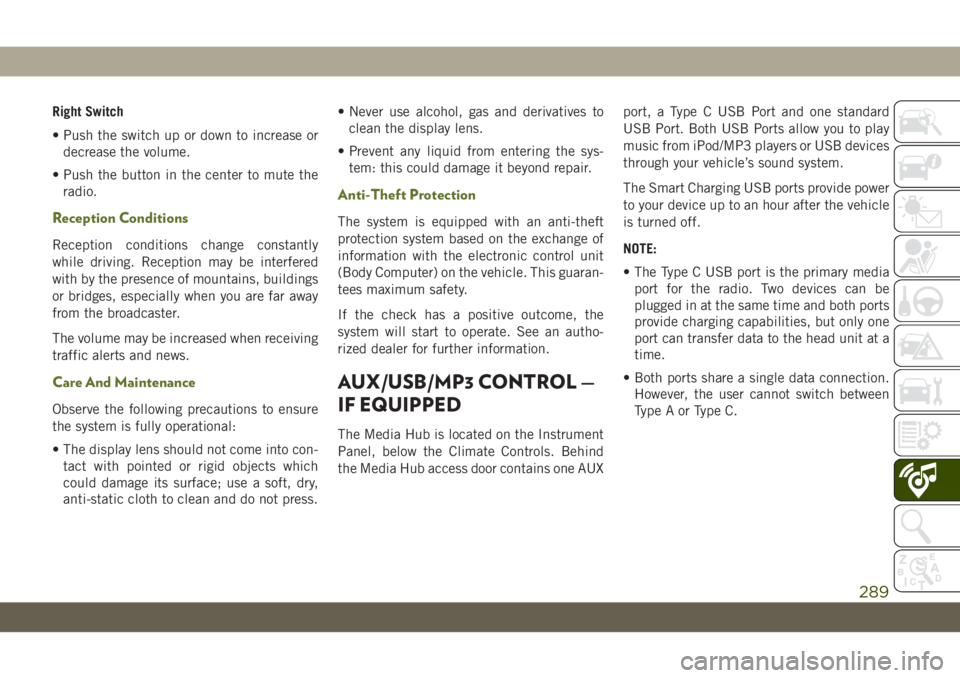
Right Switch
• Push the switch up or down to increase or
decrease the volume.
• Push the button in the center to mute the
radio.
Reception Conditions
Reception conditions change constantly
while driving. Reception may be interfered
with by the presence of mountains, buildings
or bridges, especially when you are far away
from the broadcaster.
The volume may be increased when receiving
traffic alerts and news.
Care And Maintenance
Observe the following precautions to ensure
the system is fully operational:
• The display lens should not come into con-
tact with pointed or rigid objects which
could damage its surface; use a soft, dry,
anti-static cloth to clean and do not press.• Never use alcohol, gas and derivatives to
clean the display lens.
• Prevent any liquid from entering the sys-
tem: this could damage it beyond repair.
Anti-Theft Protection
The system is equipped with an anti-theft
protection system based on the exchange of
information with the electronic control unit
(Body Computer) on the vehicle. This guaran-
tees maximum safety.
If the check has a positive outcome, the
system will start to operate. See an autho-
rized dealer for further information.
AUX/USB/MP3 CONTROL —
IF EQUIPPED
The Media Hub is located on the Instrument
Panel, below the Climate Controls. Behind
the Media Hub access door contains one AUXport, a Type C USB Port and one standard
USB Port. Both USB Ports allow you to play
music from iPod/MP3 players or USB devices
through your vehicle’s sound system.
The Smart Charging USB ports provide power
to your device up to an hour after the vehicle
is turned off.
NOTE:
• The Type C USB port is the primary media
port for the radio. Two devices can be
plugged in at the same time and both ports
provide charging capabilities, but only one
port can transfer data to the head unit at a
time.
• Both ports share a single data connection.
However, the user cannot switch between
Type A or Type C.
289
Page 310 of 348
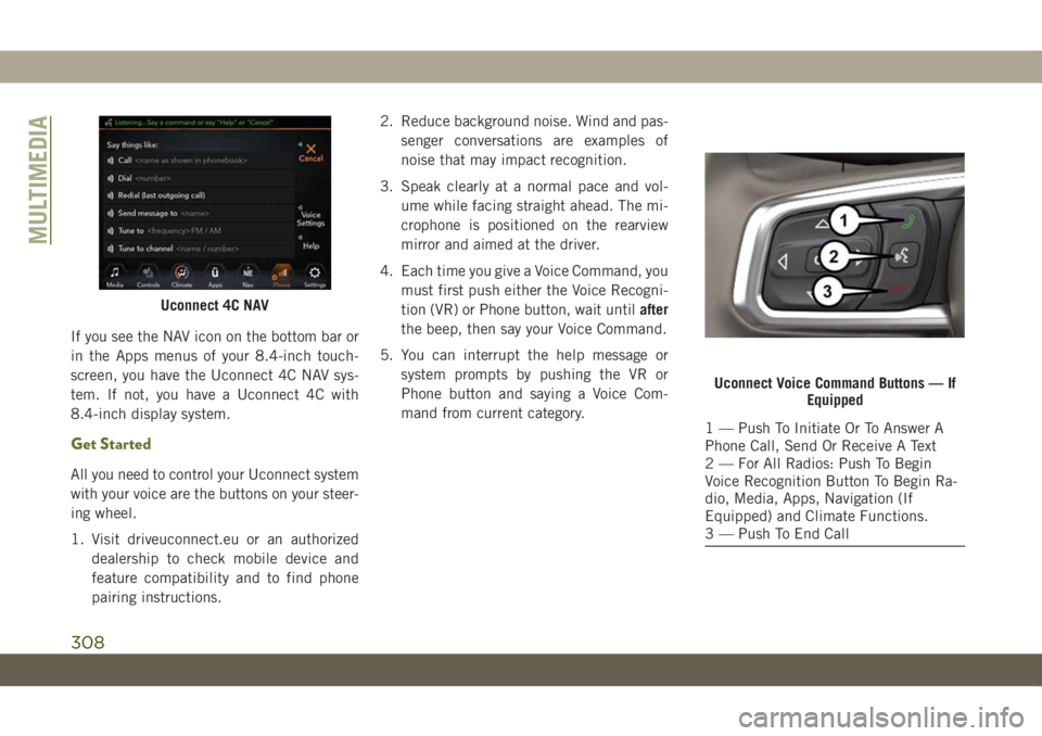
If you see the NAV icon on the bottom bar or
in the Apps menus of your 8.4-inch touch-
screen, you have the Uconnect 4C NAV sys-
tem. If not, you have a Uconnect 4C with
8.4-inch display system.
Get Started
All you need to control your Uconnect system
with your voice are the buttons on your steer-
ing wheel.
1. Visit driveuconnect.eu or an authorized
dealership to check mobile device and
feature compatibility and to find phone
pairing instructions.2. Reduce background noise. Wind and pas-
senger conversations are examples of
noise that may impact recognition.
3. Speak clearly at a normal pace and vol-
ume while facing straight ahead. The mi-
crophone is positioned on the rearview
mirror and aimed at the driver.
4. Each time you give a Voice Command, you
must first push either the Voice Recogni-
tion (VR) or Phone button, wait untilafter
the beep, then say your Voice Command.
5. You can interrupt the help message or
system prompts by pushing the VR or
Phone button and saying a Voice Com-
mand from current category.
Uconnect 4C NAV
Uconnect Voice Command Buttons — If
Equipped
1 — Push To Initiate Or To Answer A
Phone Call, Send Or Receive A Text
2 — For All Radios: Push To Begin
Voice Recognition Button To Begin Ra-
dio, Media, Apps, Navigation (If
Equipped) and Climate Functions.
3 — Push To End Call
MULTIMEDIA
308