light JEEP WRANGLER UNLIMITED 2019 Owner handbook (in English)
[x] Cancel search | Manufacturer: JEEP, Model Year: 2019, Model line: WRANGLER UNLIMITED, Model: JEEP WRANGLER UNLIMITED 2019Pages: 348, PDF Size: 6.5 MB
Page 45 of 348
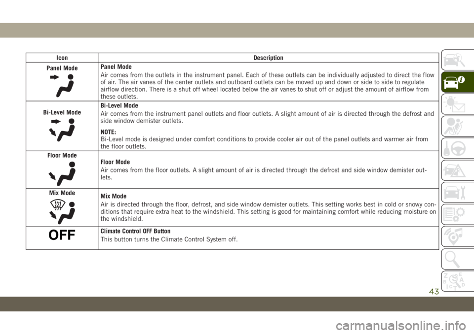
Icon Description
Panel Mode
Panel Mode
Air comes from the outlets in the instrument panel. Each of these outlets can be individually adjusted to direct the flow
of air. The air vanes of the center outlets and outboard outlets can be moved up and down or side to side to regulate
airflow direction. There is a shut off wheel located below the air vanes to shut off or adjust the amount of airflow from
these outlets.
Bi-Level Mode
Bi-Level Mode
Air comes from the instrument panel outlets and floor outlets. A slight amount of air is directed through the defrost and
side window demister outlets.
NOTE:
Bi-Level mode is designed under comfort conditions to provide cooler air out of the panel outlets and warmer air from
the floor outlets.
Floor Mode
Floor Mode
Air comes from the floor outlets. A slight amount of air is directed through the defrost and side window demister out-
lets.
Mix Mode
Mix Mode
Air is directed through the floor, defrost, and side window demister outlets. This setting works best in cold or snowy con-
ditions that require extra heat to the windshield. This setting is good for maintaining comfort while reducing moisture on
the windshield.
Climate Control OFF Button
This button turns the Climate Control System off.
43
Page 51 of 348
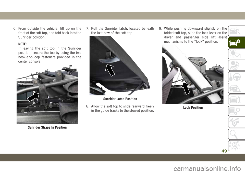
6. From outside the vehicle, lift up on the
front of the soft top, and fold back into the
Sunrider position.
NOTE:
If leaving the soft top in the Sunrider
position, secure the top by using the two
hook-and-loop fasteners provided in the
center console.7. Pull the Sunrider latch, located beneath
the last bow of the soft top.
8. Allow the soft top to slide rearward freely
in the guide tracks to the stowed position.9. While pushing downward slightly on the
folded soft top, slide the lock lever on the
driver and passenger side lift assist
mechanisms to the “lock” position.
Sunrider Straps In Position
Sunrider Latch Position
Lock Position
49
Page 57 of 348
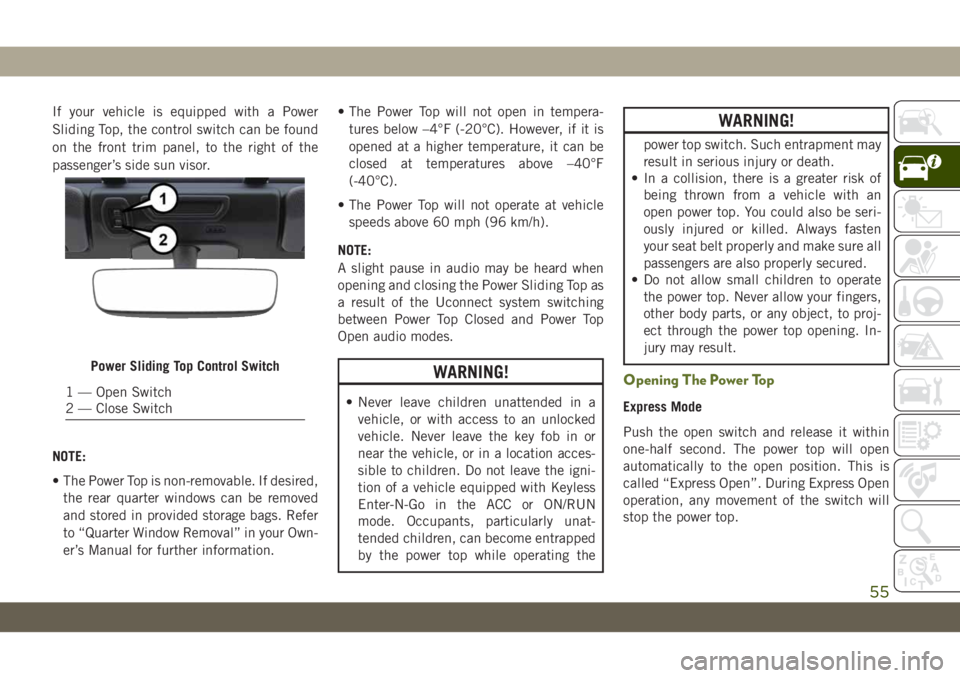
If your vehicle is equipped with a Power
Sliding Top, the control switch can be found
on the front trim panel, to the right of the
passenger’s side sun visor.
NOTE:
• The Power Top is non-removable. If desired,
the rear quarter windows can be removed
and stored in provided storage bags. Refer
to “Quarter Window Removal” in your Own-
er’s Manual for further information.• The Power Top will not open in tempera-
tures below –4°F (-20°C). However, if it is
opened at a higher temperature, it can be
closed at temperatures above –40°F
(-40°C).
• The Power Top will not operate at vehicle
speeds above 60 mph (96 km/h).
NOTE:
A slight pause in audio may be heard when
opening and closing the Power Sliding Top as
a result of the Uconnect system switching
between Power Top Closed and Power Top
Open audio modes.
WARNING!
• Never leave children unattended in a
vehicle, or with access to an unlocked
vehicle. Never leave the key fob in or
near the vehicle, or in a location acces-
sible to children. Do not leave the igni-
tion of a vehicle equipped with Keyless
Enter-N-Go in the ACC or ON/RUN
mode. Occupants, particularly unat-
tended children, can become entrapped
by the power top while operating the
WARNING!
power top switch. Such entrapment may
result in serious injury or death.
• In a collision, there is a greater risk of
being thrown from a vehicle with an
open power top. You could also be seri-
ously injured or killed. Always fasten
your seat belt properly and make sure all
passengers are also properly secured.
• Do not allow small children to operate
the power top. Never allow your fingers,
other body parts, or any object, to proj-
ect through the power top opening. In-
jury may result.
Opening The Power Top
Express Mode
Push the open switch and release it within
one-half second. The power top will open
automatically to the open position. This is
called “Express Open”. During Express Open
operation, any movement of the switch will
stop the power top.
Power Sliding Top Control Switch
1 — Open Switch
2 — Close Switch
55
Page 58 of 348
Manual Mode
To open the power top manually, push and
hold the open switch. The power top will stop
automatically at the open position. Any re-
lease of the switch will stop the movement.
The power top will remain in a partially
opened position until the switch is pushed
and held again.
Closing The Power Top
Express Mode
Push the close switch and release it within
one-half second. The power top will close
fully and stop automatically. This is called
“Express Close”. During Express Close opera-
tion, any movement of the switch will stop
the power top.
Manual Mode
To close the power top manually, push and
hold the close switch. The power top will
move forward and automatically stop at the
fully closed position. Any release of the
switch will stop the movement. The power top
will remain in a partially closed position until
the switch is pushed and held again.
Pinch Protect Feature
This feature will detect an obstruction in the
opening of the power top during Express
Close operation. If an obstruction in the path
of the power top is detected, the power top
will automatically retract. Remove the ob-
struction if this occurs. Next, push the close
switch and release to Express Close.
WARNING!
There is no anti-pinch protection when the
power top is almost closed. To avoid per-
sonal injury be sure to clear your arms,
hands, fingers and all objects from the
top’s path before closing.
NOTE:
• The Power Sliding Top may reverse motion
if closing during a severe headwind. If this
occurs, push the Power Sliding Top switch
again to close the top completely.
• If three consecutive power top close at-
tempts result in Pinch Protect reversals,
Pinch Protect will disable and the power
top must be closed in Manual Mode.
HOOD
Opening The Hood
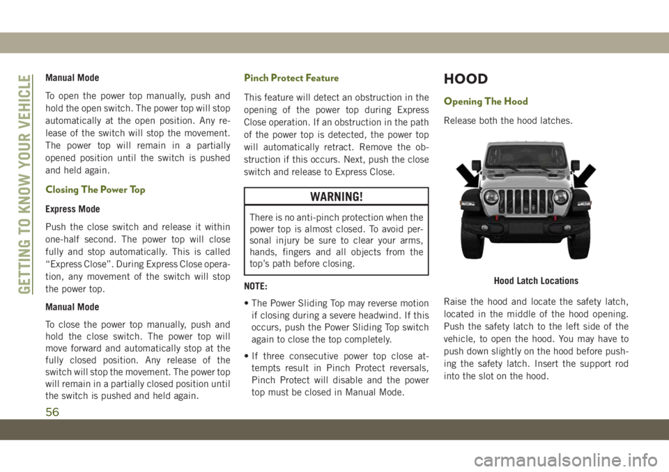
Release both the hood latches.
Raise the hood and locate the safety latch,
located in the middle of the hood opening.
Push the safety latch to the left side of the
vehicle, to open the hood. You may have to
push down slightly on the hood before push-
ing the safety latch. Insert the support rod
into the slot on the hood.
Hood Latch LocationsGETTING TO KNOW YOUR VEHICLE
56
Page 61 of 348
CAUTION!
life and/or prevent the engine from start-
ing.
• Accessories that draw higher power (i.e.,
coolers, vacuum cleaners, lights, etc.),
will degrade the battery even more
quickly. Only use these intermittently
and with greater caution.
• After the use of high power draw acces-
sories, or long periods of the vehicle not
being started (with accessories still
plugged in), the vehicle must be driven a
sufficient length of time to allow the
alternator to recharge the vehicle's bat-
tery.
• Power outlets are designed for accessory
plugs only. Do not hang any type of
accessory or accessory bracket from the
plug. Improper use of the power outlet
can cause damage.
Power Inverter — If Equipped
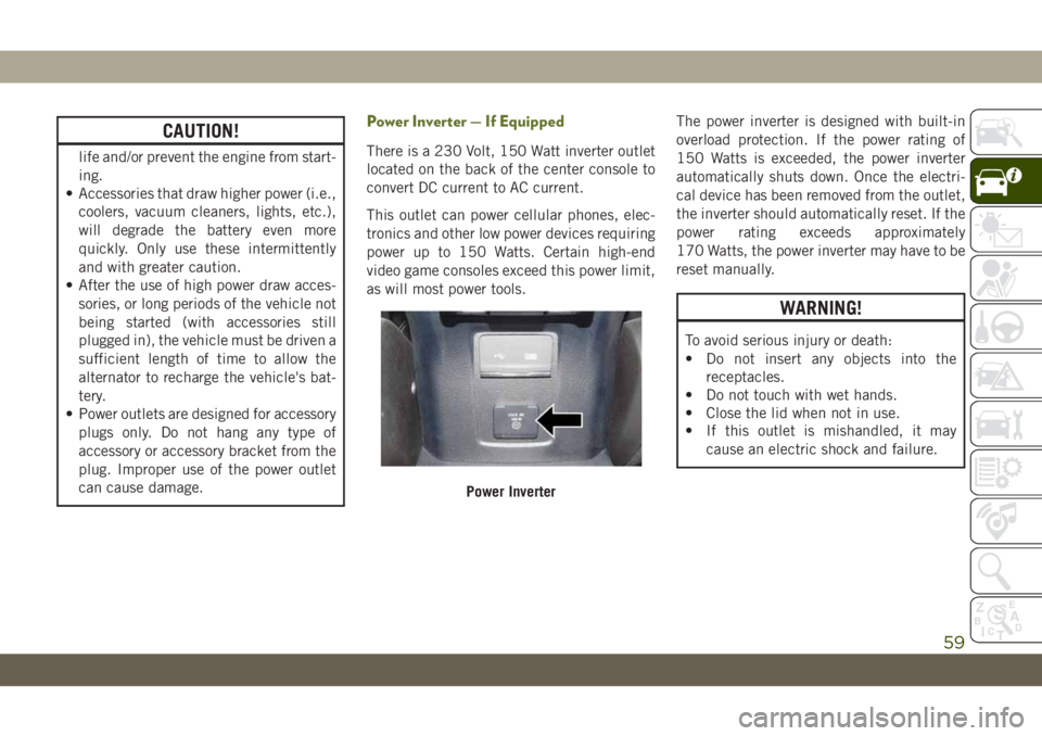
There is a 230 Volt, 150 Watt inverter outlet
located on the back of the center console to
convert DC current to AC current.
This outlet can power cellular phones, elec-
tronics and other low power devices requiring
power up to 150 Watts. Certain high-end
video game consoles exceed this power limit,
as will most power tools.The power inverter is designed with built-in
overload protection. If the power rating of
150 Watts is exceeded, the power inverter
automatically shuts down. Once the electri-
cal device has been removed from the outlet,
the inverter should automatically reset. If the
power rating exceeds approximately
170 Watts, the power inverter may have to be
reset manually.
WARNING!
To avoid serious injury or death:
• Do not insert any objects into the
receptacles.
• Do not touch with wet hands.
• Close the lid when not in use.
• If this outlet is mishandled, it may
cause an electric shock and failure.
Power Inverter
59
Page 62 of 348
Auxiliary Switches — If Equipped
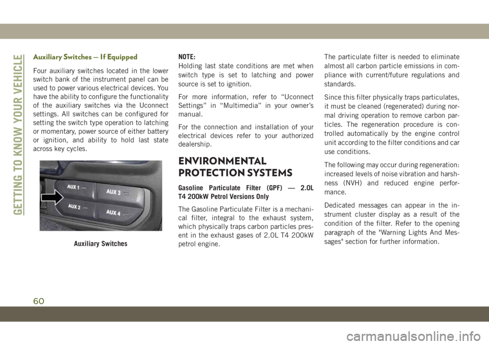
Four auxiliary switches located in the lower
switch bank of the instrument panel can be
used to power various electrical devices. You
have the ability to configure the functionality
of the auxiliary switches via the Uconnect
settings. All switches can be configured for
setting the switch type operation to latching
or momentary, power source of either battery
or ignition, and ability to hold last state
across key cycles.NOTE:
Holding last state conditions are met when
switch type is set to latching and power
source is set to ignition.
For more information, refer to “Uconnect
Settings” in “Multimedia” in your owner’s
manual.
For the connection and installation of your
electrical devices refer to your authorized
dealership.
ENVIRONMENTAL
PROTECTION SYSTEMS
Gasoline Particulate Filter (GPF) — 2.0L
T4 200kW Petrol Versions Only
The Gasoline Particulate Filter is a mechani-
cal filter, integral to the exhaust system,
which physically traps carbon particles pres-
ent in the exhaust gases of 2.0L T4 200kW
petrol engine.The particulate filter is needed to eliminate
almost all carbon particle emissions in com-
pliance with current/future regulations and
standards.
Since this filter physically traps particulates,
it must be cleaned (regenerated) during nor-
mal driving operation to remove carbon par-
ticles. The regeneration procedure is con-
trolled automatically by the engine control
unit according to the filter conditions and car
use conditions.
The following may occur during regeneration:
increased levels of noise vibration and harsh-
ness (NVH) and reduced engine perfor-
mance.
Dedicated messages can appear in the in-
strument cluster display as a result of the
condition of the filter. Refer to the opening
paragraph of the "Warning Lights And Mes-
sages" section for further information.
Auxiliary Switches
GETTING TO KNOW YOUR VEHICLE
60
Page 63 of 348
GETTING TO KNOW YOUR INSTRUMENT PANEL
INSTRUMENT CLUSTER DISPLAY. .62
Instrument Cluster Display Location And
Controls....................62
Oil Change Indicator System — If
Equipped....................63
Instrument Cluster Display Selectable
Items......................63
Gear Shift Indicator (GSI) — If
Equipped....................64Fuel System Messages............64WARNING LIGHTS AND MES-
SAGES ....................66
Red Warning Lights..............66
Yellow Warning Lights............70
Yellow Indicator Lights............74
Green Indicator Lights............75
White Indicator Lights............76Blue Indicator Lights.............77
Gray Indicator Lights.............78
ONBOARD DIAGNOSTIC SYSTEM —
OBDII ....................78
Onboard Diagnostic System (OBD II)
Cybersecurity.................78
EMISSIONS INSPECTION AND
MAINTENANCE PROGRAMS....79
GETTING TO KNOW YOUR INSTRUMENT PANEL
61
Page 67 of 348
MESSAGE DESCRIPTION
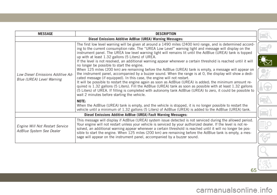
Diesel Emissions Additive AdBlue (UREA) Warning Messages:
Low Diesel Emissions Additive Ad-
Blue (UREA) Level WarningThe first low level warning will be given at around a 1490 miles (2400 km) range, and is determined accord-
ing to the current consumption rate. The “UREA Low Level” warning light and message will display on the
instrument panel. The UREA low level warning light will remains lit until the AdBlue (UREA) tank is topped
up with at least 1.32 gallons (5 Liters) of UREA.
If the level is not resolved, an additional warning appear whenever a certain threshold is reached until it will
no longer be possible to start the engine.
When 125 miles (200 km) are remaining before the AdBlue (UREA) tank is empty, a message will appear on
the instrument panel, accompanied by a buzzer sound. When the range is at 0, the display will show a dedi-
cated message (if equipped). In this case, the engine will not restart.
It will be possible to restart the engine again as soon as AdBlue (UREA) is added; the minimum amount re-
quired is 1.32 gallons (5 Liters). Fill the AdBlue (UREA) tank as soon as possible with at least 1.32 gallons
(5 Liters) of UREA. If filling is completed with autonomy tank AdBlue (UREA) to zero, it could be possible to
wait 2 minutes before starting the vehicle.
NOTE:
When the AdBlue (UREA) tank is empty, and the vehicle is stopped, it is no longer possible to restart the
vehicle until a minimum of 1.32 gallons (5 Liters) of AdBlue (UREA) is added to the AdBlue (UREA) tank.
Diesel Emissions Additive AdBlue (UREA) Fault Warning Messages:
Engine Will Not Restart Service
AdBlue System See DealerThis message will display if AdBlue (UREA) system issue detected is not serviced during the allowed period.
Your engine will not restart unless your vehicle is serviced by your authorized dealer. If the level is not re-
solved, an additional warning appear whenever a certain threshold is reached until it will no longer be pos-
sible to start the engine. When 125 miles (200 km) are remaining before the AdBlue tank is empty, a mes-
sage will appear on the instrument panel, accompanied by a buzzer sound.
65
Page 68 of 348
MESSAGE DESCRIPTION
Engine Will Not Start Service Ad-
Blue System See DealerNOTE:
• The display may take up to five seconds to update after adding 2 gallons (7.5 Liters) or more of AdBlue
(UREA) to the AdBlue (UREA) tank. If you have a fault related to the AdBlue (UREA) system, the display
may not update to the new level. See an authorized dealer for service.
• AdBlue freezes at temperatures lower than 51.8°F (11°C). If the car stands for a long time at this tem-
perature, refilling could be difficult. For this reason, it is advised to park the vehicle in a garage and/or
heated environment, and wait for the AdBlue (UREA) to return to liquid state before topping up.
Gasoline Particulate Filter (GPF) System Messages — If Equipped:
Exhaust System Service Re-
quiredThe engine control unit has detected an issue with the gasoline particulate filter system. See an autho-
rized dealer.
Exhaust System Regeneration in
Process Continue DrivingThe regeneration procedure is controlled automatically by the engine control unit according to the filter
conditions and car use conditions. The following may occur during regeneration: increased levels of noise
vibration and harshness (NVH) and reduced engine performance. The driver should continue driving nor-
mally. This message will continue to appear until regeneration is complete.
Exhaust System Regeneration
CompleteThe exhaust gas filter regeneration has been completed. This message will briefly appear.
WARNING LIGHTS AND
MESSAGES
The warning/indicator lights will illuminate in
the instrument panel together with a dedi-
cated message and/or acoustic signal when
applicable. These indications are indicative
and precautionary and as such must not be
considered as exhaustive and/or alternativeto the information contained in the Owner’s
Manual, which you are advised to read care-
fully in all cases. Always refer to the informa-
tion in this chapter in the event of a failure
indication. All active telltales will display first
if applicable. The system check menu may
appear different based upon equipment op-
tions and current vehicle status. Some tell-
tales are optional and may not appear.
Red Warning Lights
— Air Bag Warning Light
This warning light will illuminate to indicate
a fault with the air bag, and will turn on for
four to eight seconds as a bulb check when
the ignition is placed in the ON/RUN or
ACC/ON/RUN position. This light will illumi-
nate with a single chime when a fault with the
GETTING TO KNOW YOUR INSTRUMENT PANEL
66
Page 69 of 348
air bag has been detected, it will stay on until
the fault is cleared. If the light is either not on
during startup, stays on, or turns on while
driving, have the system inspected at an
authorized dealer as soon as possible.
— Brake Warning Light
This warning light monitors various brake
functions, including brake fluid level and
parking brake application. If the brake light
turns on it may indicate that the parking
brake is applied, that the brake fluid level is
low, or that there is a problem with the
anti-lock brake system.
If the light remains on when the parking
brake has been disengaged, and the fluid
level is at the full mark on the master cylinder
reservoir, it indicates a possible brake hy-
draulic system malfunction or that a problem
with the Brake Booster has been detected by
the Anti-Lock Brake System (ABS) / Elec-
tronic Stability Control (ESC) system. In this
case, the light will remain on until the condi-
tion has been corrected. If the problem is
related to the brake booster, the ABS pump
will run when applying the brake, and a brake
pedal pulsation may be felt during each stop.
The dual brake system provides a reserve brak-
ing capacity in the event of a failure to a portion
of the hydraulic system. A leak in either half of
the dual brake system is indicated by the Brake
Warning Light, which will turn on when the
brake fluid level in the master cylinder has
dropped below a specified level.
The light will remain on until the cause is
corrected.
NOTE:
The light may flash momentarily during sharp
cornering maneuvers, which change fluid
level conditions. The vehicle should have
service performed, and the brake fluid level
checked.
If brake failure is indicated, immediate repair
is necessary.
WARNING!
Driving a vehicle with the red brake light
on is dangerous. Part of the brake system
may have failed. It will take longer to stop
the vehicle. You could have a collision.
Have the vehicle checked immediately.Vehicles equipped with the Anti-Lock Brake
System (ABS) are also equipped with Elec-
tronic Brake Force Distribution (EBD). In the
event of an EBD failure, the Brake Warning
Light will turn on along with the ABS Light.
Immediate repair to the ABS system is re-
quired.
Operation of the Brake Warning Light can be
checked by turning the ignition switch from
the OFF position to the ON/RUN position.
The light should illuminate for approximately
four seconds. The light should then turn off
unless the parking brake is applied or a brake
fault is detected. If the light does not illumi-
nate, have the light inspected by an autho-
rized dealer.
The light also will turn on when the parking
brake is applied with the ignition switch in
the ON/RUN position.
NOTE:
This light shows only that the parking brake is
applied. It does not show the degree of brake
application.
67