ECO mode JEEP WRANGLER UNLIMITED 2019 Owner handbook (in English)
[x] Cancel search | Manufacturer: JEEP, Model Year: 2019, Model line: WRANGLER UNLIMITED, Model: JEEP WRANGLER UNLIMITED 2019Pages: 348, PDF Size: 6.5 MB
Page 91 of 348
Trailer Sway Control (TSC)
TSC uses sensors in the vehicle to recognize
an excessively swaying trailer and will take
the appropriate actions to attempt to stop the
sway. TSC will become active automatically
once an excessively swaying trailer is recog-
nized.
NOTE:
TSC cannot stop all trailers from swaying.
Always use caution when towing a trailer and
follow the trailer tongue weight recommenda-
tions. Refer to “Trailer Towing” in “Starting
And Operating” for further information.
When TSC is functioning, the “ESC
Activation/Malfunction Indicator Light” will
flash, the engine power may be reduced and
you may feel the brakes being applied to
individual wheels to attempt to stop the
trailer from swaying. TSC is disabled when
the ESC system is in the “Partial Off” or “Full
Off” modes.WARNING!
If TSC activates while driving, slow the
vehicle down, stop at the nearest safe
location, and adjust the trailer load to
eliminate trailer sway.
Ready Alert Braking (RAB)
Ready Alert Braking may reduce the time
required to reach full braking during emer-
gency braking situations. It anticipates when
an emergency braking situation may occur by
monitoring how fast the throttle is released by
the driver. The EBC will prepare the brake
system for a panic stop.
Rain Brake Support (RBS)
Rain Brake Support may improve braking
performance in wet conditions. It will periodi-
cally apply a small amount of brake pressure
to remove any water buildup on the front
brake rotors. It functions when the wind-
shield wipers are in LO or HI speed. When
Rain Brake Support is active, there is no
notification to the driver and no driver inter-
action is required.
Hill Descent Control (HDC) — If Equipped
HDC is intended for low speed off road driving
while in 4WD Low Range. HDC maintains
vehicle speed while descending hills during
various driving situations. HDC controls ve-
hicle speed by actively controlling the brakes.
HDC has three states:
1. Off (feature is not enabled and will not
activate).
2. Enabled (feature is enabled and ready but
activation conditions are not met, or driver
is actively overriding with brake or throttle
application).
3. Active (feature is enabled and actively
controlling vehicle speed).
Enabling HDC
HDC is enabled by pushing the HDC switch,
but the following conditions must also be met
to enable HDC:
• Driveline is in 4WD Low Range
• Vehicle speed is below 5 mph (8 km/h).
• Parking brake is released.
89
Page 93 of 348
Feedback To The Driver
The instrument cluster has an HDC icon and
the HDC switch has an indicator light, which
offers feedback to the driver about the state
HDC is in.
• The cluster icon and switch indicator light
will illuminate and remain on solid when
HDC is enabled or activated. This is the
normal operating condition for HDC.
• The cluster icon and switch indicator light
will flash for several seconds then extin-
guish when the driver pushes the HDC
switch but enable conditions are not met.
• The cluster icon and switch indicator light
will flash for several seconds then extin-
guish when HDC disables due to excess
speed.
• The cluster icon and switch indicator light
will flash when HDC deactivates due to
overheated brakes. The flashing will stop
and HDC will activate again once the brakes
have cooled sufficiently.WARNING!
HDC is only intended to assist the driver in
controlling vehicle speed when descend-
ing hills. The driver must remain attentive
to the driving conditions and is responsible
for maintaining a safe vehicle speed.
AUXILIARY DRIVING
SYSTEMS
Blind Spot Monitoring (BSM) — If
Equipped
The Blind Spot Monitoring (BSM) system
uses two radar-based sensors, located inside
the taillights, to detect highway licensable
vehicles (automobiles, trucks, motorcycles,
etc.) that enter the blind spot zones from the
rear/front/side of the vehicle.When the vehicle is started, the BSM warning
light will momentarily illuminate in both out-
side rear view mirrors to let the driver know
that the system is operational. The BSM
system sensors operate when the vehicle is in
any forward gear or REVERSE and enters
stand-by mode when the vehicle is in PARK.
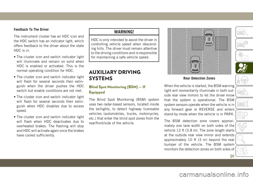
The BSM detection zone covers approxi-
mately one lane width on both sides of the
vehicle 12 ft (3.8 m). The zone length starts
at the outside rear view mirror and extends
approximately 10 ft (3 m) beyond the rear
bumper of the vehicle. The BSM system
monitors the detection zones on both sides of
Rear Detection Zones
91
Page 94 of 348
the vehicle when the vehicle speed reaches
approximately 6 mph (10 km/h) or higher and
will alert the driver of vehicles in these areas.
NOTE:
• The BSM system DOES NOT alert the driver
about rapidly approaching vehicles that are
outside the detection zones.
• The BSM system detection zone DOES NOT
change if your vehicle is towing a trailer.
Therefore, visually verify the adjacent lane
is clear for both your vehicle and trailer
before making a lane change. If the trailer
or other object (i.e., bicycle, sports equip-
ment) extends beyond the side of your ve-
hicle, this may result in the BSM warning
light remaining illuminated the entire time
the vehicle is in a forward gear.
• The Blind Spot Monitoring (BSM) system
may experience drop outs (blinking on and
off) of the side mirror Warning Indicator
lamps when a motorcycle or any small ob-
ject remains at the side of the vehicle for
extended periods of time (more than a
couple of seconds).The area on taillights, where the radar sen-
sors are located, must remain free of snow,
ice, and dirt/road contamination so that the
BSM system can function properly. Do not
block the taillights where the radar sensors
are located with foreign objects (bumper
stickers, bicycle racks, etc.).
The BSM system notifies the driver of objects
in the detection zones by illuminating the
BSM warning light located in the outside
mirrors in addition to sounding an audible
(chime) alert and reducing the radio volume.
Refer to “Modes Of Operation” for further
information.
The BSM system monitors the detection zone
from three different entry points (side, rear,
front) while driving to see if an alert is nec-
essary. The BSM system will issue an alert
during these types of zone entries.
Entering From The Side
Vehicles that move into your adjacent lanes
from either side of the vehicle.Entering From The Rear
Vehicles that come up from behind your ve-
hicle on either side and enter the rear detec-
tion zone with a relative speed of less than
30 mph (48 km/h).
Overtaking Traffic
If you pass another vehicle slowly with a
relative speed less than 15 mph (24 km/h)
and the vehicle remains in the blind spot for
approximately 1.5 seconds, the warning light
will be illuminated. If the difference in speed
between the two vehicles is greater than
15 mph (24 km/h), the warning light will not
illuminate.
The BSM system is designed not to issue an
alert on stationary objects such as guardrails,
posts, walls, foliage, berms, etc. However,
occasionally the system may alert on such
objects. This is normal operation and your
vehicle does not require service.
The BSM system will not alert you of objects
that are traveling in the opposite direction of
the vehicle in adjacent lanes.
SAFETY
92
Page 96 of 348
both the visual and audible alerts will be
issued. In addition to the audible alert the
radio (if on) will also be muted.
NOTE:
Whenever an audible alert is requested by the
BSM system, the radio is also muted.
When the system is in RCP, the system shall
respond with both visual and audible alerts
when a detected object is present. Whenever
an audible alert is requested, the radio is also
muted. Turn/hazard signal status is ignored;
the RCP state always requests the chime.
Blind Spot Alert Off
When the BSM system is turned off there will
be no visual or audible alerts from either the
BSM or RCP systems.
NOTE:
The BSM system will store the current oper-
ating mode when the vehicle is shut off. Each
time the vehicle is started the previously
stored mode will be recalled and used.Tire Pressure Monitor System (TPMS)
The Tire Pressure Monitor System (TPMS)
will warn the driver of a low tire pressure
based on the vehicle recommended cold
placard pressure.
NOTE:
• The alert warning on the cluster will stay on
until the tire is inflated to the placard
pressure.
• The system only warns the tire pressure is
low: it is not able to inflate them.
The tire pressure will vary with temperature
by approximately 1 psi (7 kPa) for every 12°F
(6.5°C). This means that when the outside
temperature decreases, the tire pressure will
decrease. Tire pressure should always be set
based on cold inflation tire pressure. This is
defined as the tire pressure after the vehicle
has not been driven for at least three hours, or
driven less than 1 mile (1.6 km) after a three
hour period. The cold tire inflation pressure
must not exceed the maximum inflation pres-
sure molded into the tire sidewall. Refer to
“Tires” in “Servicing And Maintenance” for
information on how to properly inflate thevehicle’s tires. The tire pressure will also
increase as the vehicle is driven. This is
normal and there should be no adjustment for
this increased pressure.
The TPMS will warn the driver of a low tire
pressure if the tire pressure falls below the
low-pressure warning limit for any reason,
including low temperature effects and natu-
ral pressure loss through the tire.
The TPMS will continue to warn the driver of
low tire pressure as long as the condition
exists, and will not turn off until the tire
pressure is at or above the recommended
cold placard pressure. Once the low tire pres-
sure warning (Tire Pressure Monitoring Sys-
tem Warning Light) illuminates, you must
increase the tire pressure to the recom-
mended cold placard pressure in order for the
TPMS Light to turn off.
NOTE:
When filling warm tires, the tire pressure may
need to be increased up to an additional 4 psi
(28 kPa) above the recommended cold plac-
ard pressure in order to turn the TPMS Warn-
ing Light off.
SAFETY
94
Page 101 of 348
Beginning with the next ignition cycle, the
TPMS will no longer chime or display the
“SERVICE TIRE PRESSURE SYSTEM” mes-
sage in the instrument cluster but dashes (--)
will remain in place of the pressure values.
To reactivate the TPMS, replace all four
wheel and tire assemblies (road tires) with
tires equipped with TPMS sensors. Then,
drive the vehicle for up to 10 minutes above
15 mph (24 km/h). The TPMS will chime, the
TPMS Warning Light will flash on and off for
75 seconds and then turn off. The instrument
cluster will display the “SERVICE TIRE
PRESSURE SYSTEM” message and then dis-
play pressure values in place of the dashes.
On the next ignition cycle the "SERVICE TIRE
PRESSURE SYSTEM" message will no longer
be displayed as long as no system fault exists.
OCCUPANT RESTRAINT
SYSTEMS
Some of the most important safety features in
your vehicle are the restraint systems:
Occupant Restraint Systems Features
• Seat Belt Systems
• Supplemental Restraint Systems (SRS) Air
Bags
• Child Restraints
Some of the safety features described in this
section may be standard equipment on some
models, or may be optional equipment on
others. If you are not sure, ask an authorized
dealer.
Important Safety Precautions
Please pay close attention to the information
in this section. It tells you how to use your
restraint system properly, to keep you and
your passengers as safe as possible.
Here are some simple steps you can take to
minimize the risk of harm from a deploying
air bag:
1. Children 12 years old and under should
always ride buckled up in the rear seat of
a vehicle with a rear seat.2. A child who is not big enough to wear the
vehicle seat belt properly (Refer to “Child
Restraints” in this section for further in-
formation) must be secured in the appro-
priate child restraint or belt-positioning
booster seat in a rear seating position.
3. If a child from 2 to 12 years old (not in a
rear-facing child restraint) must ride in
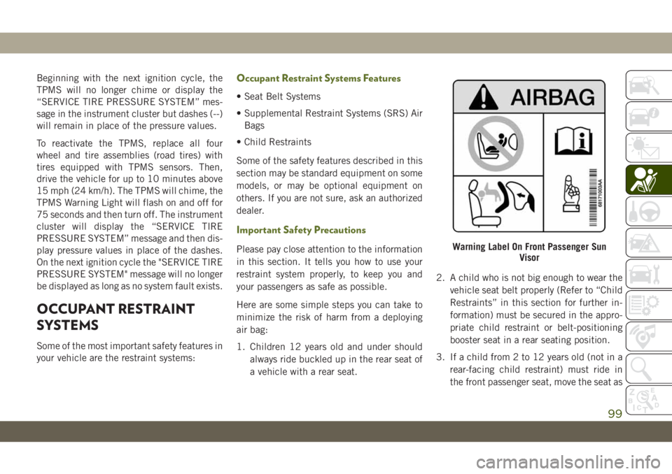
the front passenger seat, move the seat asWarning Label On Front Passenger Sun
Visor
99
Page 137 of 348
retractor can be “switched” into a locked
mode by pulling all of the webbing out of the
retractor and then letting the webbing retract
back into the retractor. If it is locked, the ALR
will make a clicking noise while the webbing
is pulled back into the retractor. Refer to the
“Automatic Locking Mode” description in
“Switchable Automatic Locking Retractors
(ALR)” under “Occupant Restraint Systems”
for additional information on ALR.
Installing A Child Restraint With A Switch-
able Automatic Locking Retractor (ALR)
Child restraint systems are designed to be
secured in vehicle seats by lap belts or the lap
belt portion of a lap/shoulder belt.
WARNING!
• Improper installation or failure to prop-
erly secure a child restraint can lead to
failure of the restraint. The child could
be badly injured or killed.
• Follow the child restraint manufacturer’s
directions exactly when installing an in-
fant or child restraint.1. Place the child seat in the center of the
seating position. For some second row
seats, you may need to recline the seat
and/or raise the head restraint (if adjust-
able) to get a better fit. If the rear seat can
be moved forward and rearward in the
vehicle, you may wish to move it to its
rear-most position to make room for the
child seat. You may also move the front
seat forward to allow more room for the
child seat.
2. Pull enough of the seat belt webbing from
the retractor to pass it through the belt
path of the child restraint. Do not twist the
belt webbing in the belt path.
3. Slide the latch plate into the buckle until
you hear a “click.”
4. Pull on the webbing to make the lap
portion tight against the child seat.
5. To lock the seat belt, pull down on the
shoulder part of the belt until you have
pulled all the seat belt webbing out of the
retractor. Then, allow the webbing to re-
tract back into the retractor. As the web-bing retracts, you will hear a clicking
sound. This means the seat belt is now in
the Automatic Locking mode.
6. Try to pull the webbing out of the retractor.
If it is locked, you should not be able to
pull out any webbing. If the retractor is not
locked, repeat step 5.
7. Finally, pull up on any excess webbing to
tighten the lap portion around the child
restraint while you push the child restraint
rearward and downward into the vehicle
seat.
8. Test that the child restraint is installed
tightly by pulling back and forth on the
child seat at the belt path. It should not
move more than 25 mm in any direction.
Any seat belt system will loosen with time, so
check the belt occasionally, and pull it tight if
necessary.
Suitability of Passenger Seats for i-Size
Child Restraint System Use
The rear outboard seats of the vehicle are
type-approved to house the state-of-the-art
i-Size child restraint systems.
135
Page 139 of 348
WARNING!
In a collision, people riding in these
areas are more likely to be seriously
injured or killed.
• Do not allow people to ride in any area of
your vehicle that is not equipped with
seats and seat belts.
• Be sure everyone in your vehicle is in a
seat and using a seat belt properly.
Exhaust Gas
WARNING!
Exhaust gases can injure or kill. They con-
tain carbon monoxide (CO), which is col-
orless and odorless. Breathing it can make
you unconscious and can eventually poi-
son you. To avoid breathing (CO), follow
these safety tips:
• Do not run the engine in a closed garage
or in confined areas any longer than
needed to move your vehicle in or out of
the area.
WARNING!
• If you are required to drive with the
trunk/liftgate/rear doors open, make sure
that all windows are closed and the cli-
mate control BLOWER switch is set at
high speed. DO NOT use the recircula-
tion mode.
• If it is necessary to sit in a parked vehicle
with the engine running, adjust your
heating or cooling controls to force out-
side air into the vehicle. Set the blower
at high speed.
The best protection against carbon monoxide
entry into the vehicle body is a properly main-
tained engine exhaust system.
Whenever a change is noticed in the sound of
the exhaust system, when exhaust fumes can
be detected inside the vehicle, or when the
underside or rear of the vehicle is damaged,
have a competent mechanic inspect the com-
plete exhaust system and adjacent body ar-
eas for broken, damaged, deteriorated, or
mispositioned parts. Open seams or loose
connections could permit exhaust fumes to
seep into the passenger compartment. Inaddition, inspect the exhaust system each
time the vehicle is raised for lubrication or oil
change. Replace as required.
Safety Checks You Should Make Inside
The Vehicle
Seat Belts
Inspect the seat belt system periodically,
checking for cuts, frays, and loose parts.
Damaged parts must be replaced immedi-
ately. Do not disassemble or modify the sys-
tem.
Front seat belt assemblies must be replaced
after a collision. Rear seat belt assemblies
must be replaced after a collision if they have
been damaged (i.e., bent retractor, torn web-
bing, etc.). If there is any question regarding
seat belt or retractor condition, replace the
seat belt.
Air Bag Warning Light
The Air Bag warning lightwill turn on for
four to eight seconds as a bulb check when
the ignition switch is first turned to ON/RUN.
If the light is either not on during starting,
137
Page 140 of 348
stays on, or turns on while driving, have the
system inspected at an authorized dealer as
soon as possible. After the bulb check, this
light will illuminate with a single chime when
a fault with the Air Bag System has been
detected. It will stay on until the fault is
removed. If the light comes on intermittently
or remains on while driving, have an autho-
rized dealer service the vehicle immediately.
Refer to “Occupant Restraint Systems” in
“Safety” for further information.
Defroster
Check operation by selecting the defrost
mode and place the blower control on high
speed. You should be able to feel the air
directed against the windshield. See an au-
thorized dealer for service if your defroster is
inoperable.
Floor Mat Safety Information
Always use floor mats designed to fit your
vehicle. Only use a floor mat that does not
interfere with the operation of the accelera-
tor, brake or clutch pedals. Only use a floor
mat that is securely attached using the floormat fasteners so it cannot slip out of position
and interfere with the accelerator, brake or
clutch pedals or impair safe operation of your
vehicle in other ways.
WARNING!
An improperly attached, damaged, folded,
or stacked floor mat, or damaged floor mat
fasteners may cause your floor mat to
interfere with the accelerator, brake, or
clutch pedals and cause a loss of vehicle
control. To prevent SERIOUS INJURY or
DEATH:
• ALWAYS securely attach
your floor
mat using the floor mat fasteners. DO
NOT install your floor mat upside down
or turn your floor mat over. Lightly pull to
confirm mat is secured using the floor
mat fasteners on a regular basis.
• ALWAYS REMOVE THE EXISTING
FLOOR MAT FROM THE VEHICLE
before installing any other floor mat.
NEVER install or stack an additional
floor mat on top of an existing floor mat.
• ONLY install floor mats designed to fit
your vehicle. NEVER install a floor mat
WARNING!
that cannot be properly attached and
secured to your vehicle. If a floor mat
needs to be replaced, only use a FCA
approved floor mat for the specific
make, model, and year of your vehicle.
• ONLY use the driver’s side floor mat on
the driver’s side floor area. To check for
interference, with the vehicle properly
parked with the engine off, fully depress
the accelerator, the brake, and the
clutch pedal (if present) to check for
interference. If your floor mat interferes
with the operation of any pedal, or is not
secure to the floor, remove the floor mat
from the vehicle and place the floor mat
in your trunk.
• ONLY use the passenger’s side floor mat
on the passenger’s side floor area.
• ALWAYS make sure objects cannot fall
or slide into the driver’s side floor area
when the vehicle is moving. Objects can
become trapped under accelerator,
brake, or clutch pedals and could cause
a loss of vehicle control.
SAFETY
138
Page 143 of 348
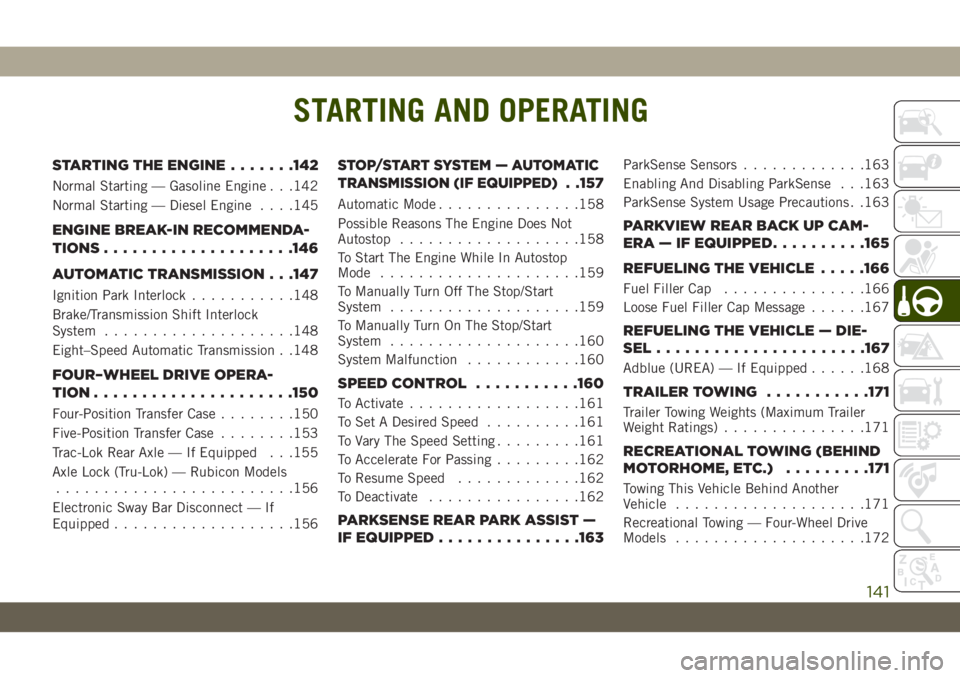
STARTING AND OPERATING
STARTING THE ENGINE.......142
Normal Starting — Gasoline Engine . . .142
Normal Starting — Diesel Engine. . . .145
ENGINE BREAK-IN RECOMMENDA-
TIONS....................146
AUTOMATIC TRANSMISSION . . .147
Ignition Park Interlock...........148
Brake/Transmission Shift Interlock
System....................148
Eight–Speed Automatic Transmission . .148
FOUR–WHEEL DRIVE OPERA-
TION.....................150
Four-Position Transfer Case........150
Five-Position Transfer Case........153
Trac-Lok Rear Axle — If Equipped . . .155
Axle Lock (Tru-Lok) — Rubicon Models
.........................156
Electronic Sway Bar Disconnect — If
Equipped...................156
STOP/START SYSTEM — AUTOMATIC
TRANSMISSION (IF EQUIPPED)
. .157
Automatic Mode...............158
Possible Reasons The Engine Does Not
Autostop...................158
To Start The Engine While In Autostop
Mode.....................159
To Manually Turn Off The Stop/Start
System....................159
To Manually Turn On The Stop/Start
System....................160
System Malfunction............160
SPEED CONTROL...........160
To Activate..................161
To Set A Desired Speed..........161
To Vary The Speed Setting.........161
To Accelerate For Passing.........162
To Resume Speed.............162
To Deactivate................162
PARKSENSE REAR PARK ASSIST —
IF EQUIPPED...............163
ParkSense Sensors.............163
Enabling And Disabling ParkSense . . .163
ParkSense System Usage Precautions . .163
PARKVIEW REAR BACK UP CAM-
ERA — IF EQUIPPED..........165
REFUELING THE VEHICLE.....166
Fuel Filler Cap...............166
Loose Fuel Filler Cap Message......167
REFUELING THE VEHICLE — DIE-
SEL......................167
Adblue (UREA) — If Equipped......168
TRAILER TOWING...........171
Trailer Towing Weights (Maximum Trailer
Weight Ratings)...............171
RECREATIONAL TOWING (BEHIND
MOTORHOME, ETC.).........171
Towing This Vehicle Behind Another
Vehicle....................171
Recreational Towing — Four-Wheel Drive
Models....................172
STARTING AND OPERATING
141
Page 144 of 348
STARTING THE ENGINE
Before starting your vehicle, adjust your seat,
adjust both inside and outside mirrors, and
fasten your seat belts.
WARNING!
• When exiting the vehicle, always remove
the key fob from the vehicle and lock
your vehicle.
• Never leave children alone in a vehicle,
or with access to an unlocked vehicle.
• Allowing children to be in a vehicle un-
attended is dangerous for a number of
reasons. A child or others could be seri-
ously or fatally injured. Children should
be warned not to touch the parking
brake, brake pedal or the transmission
gear selector.
• Do not leave the key fob in or near the
vehicle, or in a location accessible to
children, and do not leave the ignition of
a vehicle equipped with Keyless Enter-
N-Go in the ACC or ON/RUN mode. A
child could operate power windows,
other controls, or move the vehicle.
WARNING!
• Do not leave children or animals inside
parked vehicles in hot weather. Interior
heat build-up may cause serious injury
or death.
Normal Starting — Gasoline Engine
To Turn On The Engine Using The ENGINE
START/STOP Button
1. The transmission must be in PARK or
NEUTRAL.
2. Press and hold the brake pedal while
pushing the ENGINE START/STOP button
once.
3. The system takes over and attempts to
start the vehicle. If the vehicle fails to
start, the starter will disengage automati-
cally after 10 seconds.
4. If you wish to stop the cranking of the
engine prior to the engine starting, push
the button again.NOTE:
Normal starting of either a cold or a warm
engine is obtained without pumping or press-
ing the accelerator pedal.
To Turn Off The Engine Using ENGINE START/
STOP Button
1. Place the gear selector in PARK, then
push and release the ENGINE START/
STOP button.
2. The ignition will return to the OFF mode.
3. If the gear selector is not in PARK (with
vehicle stopped) and the ENGINE START/
STOP button is pushed once, the trans-
mission will automatically select PARK
and the engine will turn off, however the
ignition will remain in the ACC mode
(NOT the OFF mode). Never leave a ve-
hicle out of the PARK position, or it could
roll.
4. If the gear selector is in NEUTRAL, and
the vehicle speed is below 5 mph
(8 km/h), pushing the START/STOP but-
ton once will turn the engine off. The
ignition will remain in the ACC mode.
STARTING AND OPERATING
142